Advertisement
Model: 5250DF
Dual Fuel Generator
OPERATOR'S MANUAL
CPO Commerce, LLC
60 Crestridge DR
Suwanee, GA 30024
Customer service#: 1-866-577-3014
EMAIL: customerservice@cpocommerce.com
SAVE THIS MANUAL FOR FUTURE REFERENCE
This manual contains important information regarding safety, operation, and maintenance.
,
Advertisement
Table of Contents

Related Manuals for Quipall 5250DF

Summary of Contents for Quipall 5250DF
- Page 1 Model: 5250DF Dual Fuel Generator OPERATOR’S MANUAL CPO Commerce, LLC 60 Crestridge DR Suwanee, GA 30024 Customer service#: 1-866-577-3014 EMAIL: customerservice@cpocommerce.com SAVE THIS MANUAL FOR FUTURE REFERENCE This manual contains important information regarding safety, operation, and maintenance.
-
Page 2: Table Of Contents
5250W Generator Table of Contents Topic Page Safety Guidelines Genera a a l al Precautions General Parts Operation Inspection, Cleaning and Maintenance Installation roubles ooting Specifications Wiring iagram... -
Page 3: Safety Guidelines
Safety Guidelines - Definitions This manual contains important information that you need to know and understand in order to protect YOUR SAFETY and to PREVENT EQUIPMENT PROBLEMS. The following symbols help you recognize this information. Please read the manual and pay attention to these sections. Save These Important Safety Instructions! Read and understand all of these safety instructions. -
Page 4: Genera A A L Al Precautions Gui Elines
General Precautions WARNING! FAILURE TO FOLLOW THESE INSTRUCTIONS CAN RESULT IN SEVERE INJURY OR DEATH. CAUTION: FAILURE TO FOLLOW THESE INSTRUCTIONS CAN ALSO RESULT IN DAMAGE TO THE TOOL AND/OR THE ITEM YOU ARE WORKING Carbon Monoxide When this tool is running, ensure that the area is well ventilated. Never run the engine in an enclosed area. - Page 5 General Precautions Gasoline and Oil • Do not smoke, or allow sparks, flames or other sources of ignition around the engine and fuel tank. Fuel vapors are explosive. • Keep grounded conductive objects, such as tools, away from exposed, live electrical parts and connections to avoid sparking or arcing.
- Page 6 General Precautions Work Area • Keep your work area clean and well lit. Cluttered benches and dark areas invite accidents. • Do not operate power tools in explosive atmospheres, such as in the presence of flammable liquids, gases, or dust. Generators create sparks which may ignite the dust or fumes. •...
- Page 7 General Precautions Electrical Safety • All connections and conduits from the generator to the load must only be installed by trained and licensed electricians, and in compliance with all relevant local, state, and federal electrical codes and standards, and other regulations where applicable. •...
- Page 8 General Precautions Personal Safety • Avoid accidental starting. Make sure the power switch is in its “OFF” position and disconnect the spark plug wire when not in use. • Remove adjusting keys or wrenches before turning the generator on. A wrench or a key that is left attached to a rotating part of the generator may result in personal injury.
- Page 9 General Precautions Servicing Maintain labels and name plates on the generator and engine. These carry important information. If unreadable or missing, contact Pulsar Products Inc. Immediately for a replacement. Generator service must be performed only by qualified repair personnel. Service or maintenance performed by unqualified personnel could result in a risk of injury.
- Page 10 General Precautions Installation • If the generator is installed outdoors, it must be weatherproofed and should be soundproofed. It should not be run outdoors without protection to the generator and wiring conduit. • The generator weighs lbs (approximately) . Two or more people should assist when moving or lifting this product.
- Page 11 General Precautions Mechanical • Do not operate the generator with safety guards removed. While the generator is running, do not attempt to reach around the safety guard for maintenance or any other reason. • Keep hands, arms, long hair, loose clothing, and jewelry away from moving parts. Be aware that when engine parts are moving fast they cannot be seen clearly.
-
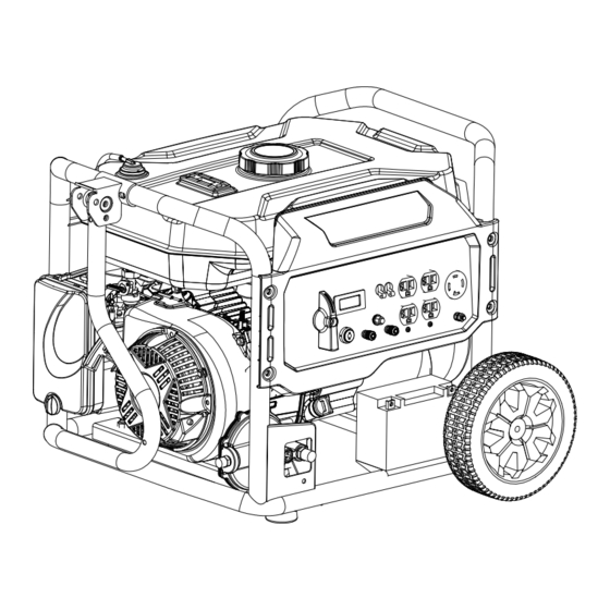
Page 12: General Parts
Ge n ra l Pa s Fuel tank Fuel tank cap Frame One way valve Fuel valve Control Panel Choke lever Wheel Air filter Recoil starter Fuel Selector Switch Oil dipstick On/off switch Voltage frequency Voltage frequency DC Protector Main Breaker hour meter AC 120/240V Receptacle... -
Page 13: Operation
Operation NOTE: THE PARTS LISTED ABOVE ARE HELPFUL FOR LOCATING THE CONTROLS MENTIONED BELOW. CAUTION: PRIOR TO FIRST USING THE GENERATOR, THE ENGINE MUST BE FILLED WITH A HIGH QUALITY SAE 10W-30 GRADE ENGINE OIL. TO DO SO, UNSCREW AND REMOVE THE ENGINE’S OIL DIPSTICK LOCATED AT THE BOTTOM OF THE ENGINE CRANKCASE. - Page 14 Operation Connecting to LPG Fuel Source 1.Locate the LPG converter on the front of the generator. 2.Attach small end of the Gas Hose to the LPG converter. 3.Connect gas hose to propane fuel source. Do not turn on propane source prior to following the steps outlined. Starting the Generator Set Ground Terminal Before using generator, a ground wire must be connected to the ground terminal.
- Page 15 Operation RECOIL START METHOD 1. Disconnect all devices from the outlets on the generator panel. 2. Press the engine switch to the "ON" position. 3. Grasp the recoil starter handle and pull it until the engine starts. Do not allow the recoil starter to snap back. Return it slowly by hand...
- Page 16 Operation 4. Push the choke lever to the OPEN position as the engine warms up. The choke is used to provide the proper mixture when the engine is cold. It can be opened and closed by operating the choke lever manually by starting.
- Page 17 Operation Stopping the Generator Set When using gasoline 1.Turn off all the connected devices. 2.Allow the generator set run for a few minutes to cool down. 3.Stop the generator set by pressing and holding the engine switch in the OFF position until the generator set stops. 4.Rotate the fuel valve lever back to the OFF position.
- Page 18 Operation Powering 120 Volt AC Tools a nd Equipment: 1. Prior to powering tools and equipment, make sure the generator’s rated voltage, and amperage capacity (120VAC @ 27 AMPs) is adequate to supply all electrical loads that the unit will power.
- Page 19 Operation Powering 12 Volt DC tools and Equipment: 1. Prior to powering tools and equipment, make sure the generator’s rated voltage, and amperage capacity (12VDC) is adequate to supply all electrical loads that the unit will power. If powering exceeds the generator’s capacity, it may be necessary to group one or more of the tools and/or equipment for connection to a separate generator.
- Page 20 Operation Spark Plug Service In order to service the spark plug, you will need a spark plug wrench (commercially available). Recommended spark plugs: NHSP LD F7TC. To ensure proper engine operation, the spark plug must be properly gapped and free of deposits. 1.
-
Page 21: Inspection, Cleaning And Maintenance
Inspection, Cleaning, and Maintenance WARNING! ALWAYS MAKE SURE THE ENGINE POWER SWITCH (2) IS IN ITS “OFF” POSITION. DISCONNECT THE SPARK PLUG WIRE FROM THE ENGINE. AND ALLOW SUFFICIENT TIME FOR THE ENGINE AND GENERATOR TO COMPLETELY COOL BEFORE PERFORMING ANY INSPECTIONS, MAINTENANCE, OR CLEANING. -
Page 22: Installation
Installation NOTE: PRIOR TO POWERING TOOLS AND EQUIPMENT MAKE SURE THE GENERATOR’S RATED VOLTAGE, WATTAGE AND AMPERAGE CAPACITY IS ADEQUATE TO SUPPLY ALL ELECTRICAL LOADS THAT THE UNIT WILL POWER. IF POWERING EXCEEDS THE GENERATOR’S CAPACITY, IT MAY BE NECCESSARY TO GROUP ONE OR MORE OF THE TOOLS AND/OR EQUIPMENT FOR CONNECTION TO A SEPERATE GENERATOR. - Page 23 Installation Supporting and Mounting Mount the generator on a concrete slab capable of supporting the weight of the generator. The slab must extend on all sides beyond the frame by at least one foot. Contact a cement contractor for slab specifications if necessary. Attach the frame to the concrete slab using 3/8” diameter expansion anchor bolts (not supplied).
-
Page 24: T Roubles Ooting H
Troubleshooting Note: Troubleshooting problems may have similar causes and solutions. PROBLEM POSSIBLE CAUSE SOLUTION Is there fuel in the tank? Refill the fuel tank. Is there enough oil in the The engine Add the recommended oil. engine? will not start Is the spark plug in good Readjust gap and dry the spark plug. -
Page 25: Specifications
Specifications 5250DF Model G AS Max.Power 5.25kW 4.75kW R ated Power 4.25kW 3.85kW AC output Frequency 60Hz 120V / 240V Voltage Power Factor Engine Model DHLG225 Type 4 Strokes / Air Cooling / Single Cylinder / OHV/ Horizontal Shaft Displacement(cc) -
Page 26: Wiring D Iagram
Wiring Diagra 03-017/1...
Need help?
Do you have a question about the 5250DF and is the answer not in the manual?
Questions and answers