
Summary of Contents for Polychem PC1000P
- Page 1 PC1000P PC1000SP OPERATION MANUAL | SPARE PARTS LIST POLYCHEM CORPORATION 6277 HEISLEY ROAD, MENTOR, OHIO 44060 PHONE: 440.357.1500, FAX: 440.352.9553 WWW.POLYCHEM.COM...
-
Page 3: Table Of Contents
CONTENTS PART I 1 General Safety Instructions..............A1 1.1 Basic Operation ................. A1 1.2 Basic Safety Precautions ............A1 1.3 Safety Instructions Governing Specific Operational Phases ..A2 1.4 Warning of Electrical Dangers ..........A3 1.5 Grounding Instructions Shall Include the Following ....A3 1.6 Before Operating ............... - Page 4 3 Preparation Before Operating the Machine ........A12 3.1 Shipping .................. A12 3.2 Transportation & Centre of Gravity ........A12 3.3 Construction Layout..............A13 3.4 Installation................A16 3.5 Operation Space ..............A19 3.6 Operating Elements ..............A20 3.7 Instructions for Loading PP Strap ........... A22 3.8 Auto Strap Feeding Process ............
- Page 5 5.7! Speed and Pressure Adjustment of Press Bar ......A35 5.8! Adjustment on the Stop position (height) of Press Bar ... A36 6. Troubleshooting ................A36 7. Maintenance..................A39 PART II 1. Pneumatic System Diagram (For TP-702P)........B1 2. Wiring Diagram ..................B2 PART III 1.
-
Page 7: Part I
PART I... -
Page 8: General Safety Instructions
1! General Safety Instructions 1.1! Basic Operation Read the operation and safety manual prior to using the strapping machine. The operation and safety manual should remain attached to the machine at all times. The machine may only be operated in accordance with its designated use. The strapping machine was built in accordance with state-of-the-art standards and recognized safety rules. -
Page 9: Safety Instructions Governing Specific Operational Phases
1.3! Safety Instructions Governing Specific Operational Phases Avoid unsafe operation of the equipment. The machine is only to be operated when it is in good running order. Only operate the equipment in a safe manner; all protective and safety devices must be in place and fully functional. -
Page 10: Warning Of Electrical Dangers
1.4! Warning of Electrical Dangers Immediately remove power to the machine in case of trouble in the electrical system. Replace a fuse with one with the same style and ratings; pay particular attention to matching the specified current. Any electrical work performed on the equipment must be conducted by a skilled electrician or under the supervision of a skilled electrician. -
Page 11: Before Operating
1.6! Before Operating Read the instruction manual before operating the machine for your safety. Wear eye protection and safety gloves before operating this machine. Eye protection must be worn Safety gloves must be worn Ear protection must be worn Verify that the power line voltage is correct. The machine must be properly grounded to avoid a shock hazard. -
Page 12: Signs And Symbols
1.9! Signs and Symbols Symbol Meaning Warning for dangerous voltage! Contact with live electrical parts will result in severe injury or death. Warning for hot surface! Welding area is approximately 270 Allow sufficient time for the heater to cool down before any work in welding area. Warning for danger! Do not put your hands or body into arch working area when machine is... -
Page 13: Machine Information
2! Machine Information 2.1! Areas of Application The strapping machine is to be used for strapping packages, cartons, paper boxes, newspapers, magazines and those materials using a polypropylene (PP) strapping for stabilizing purposes when in transportation. Be careful for rigidity of working materials, and don’t try to pack agri-foodstuffs or other such material. -
Page 14: Storage
And the user should refer to a professional expert or relevant authority to prevent the dangerous substance/ gas emitted by suitable means according to local /national environmental/health codes/regulations. 2.3! Storage The store room must be dry Do not expose the machine to extreme cold or heat environment Place the machine on an even floor in order to avoid any distortion 2.4! Machine Description Automatic strapping machine for polypropylene (PP) strapping material. -
Page 15: Safety Devices
2.5! Safety Devices Danger! Operate the machine only when all safety devices are at their place and are functioning correctly. The machine has been constructed in accordance with the applicable legal regulations. The machine is reliable in operation. Nevertheless the machine may constitute a danger if it is operated in improper or undue condition. -
Page 16: Technical Specification
For TP-702RS If it is necessary to make adjustments inside the machine during operation, after a strap jam for example, the rear table top can be unscrewed. Observe caution as the machine is still fully functional with the covers removed. When the front table top is opened, safety switch B6 is activated. - Page 17 2.6.2! Technical Data (For TP-702P-59) (Option) Strap width 5mm, 6mm, 9mm Strap thickness 0.35mm up to 0.65mm (0.014” – 0.026”) Coil diameter 200mm (8” nominal) Strap coil diameter Outside diameter 420mm (16.5”) Width(Face) 190mm (7.5”) Minimum – 820mm (32.3”) Table height Maximum –...
- Page 18 2.6.3! Technical Data (For TP-702RS) Strap width 5mm, 6mm, 9mm Strap thickness 0.35mm up to 0.65mm (0.014” – 0.026”) Coil diameter 200mm (8” nominal) Strap coil diameter Outside diameter 420mm (16.5”) Width(Face) 190mm (7.5”) Minimum – 820mm (32.3”) Table height Maximum –...
-
Page 19: Preparation Before Operating The Machine
3! Preparation Before Operating the Machine 3.1! Shipping The equipment is delivered in transport units. Each transport unit is loaded onto a wooden pallet, secured by polyester strapping. 3.2! Transportation & Centre of Gravity The machine must be secured on a pallet for transportation. -
Page 20: Construction Layout
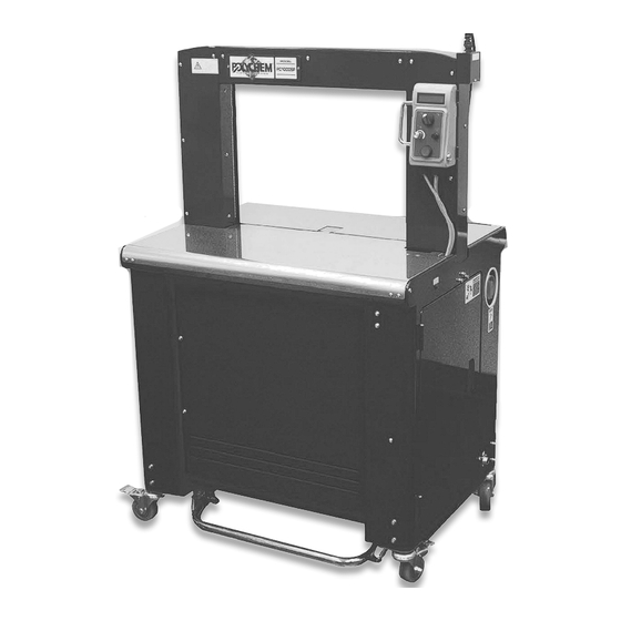
3.3! Construction Layout 3.3.1 For TP-702P-59 1.! Arch 2.! Upper Table Front 3.! Adjustment Leg 4.! Reel 5.! Foot Bar (Front) 6.! Caster (Brake) 7.! Reel Brake Release 8.! Caster (Free) 9.! Foot Pedal (Option) 10.!Side Door 11.!Control Panel 12.!Power Cord 13.!Strapping Head Unit 14.!Main Motor M1 15.!Feed Motor M2... - Page 21 22.!Fan (M11) 23.!Heater 24.!Photo Eye (Option) 25.!Timer Box (Option) 26.!Foot Bar (Rear)(Option) 27.!Press Bar (hold down device) 28.!Safety Guard (Option) 29.!Air F.R.L. Combination (Filter/Regulator/Lubricator) 3.3.2!For TP-702P-59 (With Low Table)(Option) 1.! Arch 2.! Upper Table Front 4. Reel 6.! Caster (Brake) 7.! Reel Brake Release 8.! Caster (Free) 9.! Foot Pedal...
- Page 22 15.!Feed Motor M2 16.!Tension Motor M3 17.!Strap Accumulator Motor M4 18.!Automatic Feed Motor M5 19.!Proximity Sensor SQ1 20.!Proximity Sensor SQ2 21.!Proximity Sensor SQ3 22.!Fan (M11) 23.!Heater 24.!Photo Eye (Option) 25.!Timer Box (Option) 27.!Press Bar (hold down device) 28.!Safety Guard (Option) 29.!Air F.R.L Combination (Filter/Regulator/Lubricator) 3.3.3!For TP-702RS 1.! Arch...
-
Page 23: Installation
12.!Power Cord 13.!Strapping Head Unit 14.!Main Motor M1 15.!Feed Motor M2 16.!Tension Motor M3 17.!Strap Accumulator Motor M4 18.!Automatic Feed Motor M5 19.!Proximity Sensor SQ1 20.!Proximity Sensor SQ2 21.!Proximity Sensor SQ3 22.!Fan (M11) 23.!Heater 24.!Photo Eye (Option) 25.!Timer Box (Option) 26.!Foot Bar (Rear)(Option) 3.4! Installation 1.! Remove the packing material and check that the machine is complete and without... - Page 24 c.! Have M7-4-101200 Shaft threading from inside of the machine and then lift the Reel Group and move the Gas Spring to make the PIN also goes through the hole and use 2 Allan Key with 3mm to fix THS0508N+PW05+SW05 all together.
- Page 25 6.! Do not move the machine unless it’s necessary. Before movement, be sure to turn off the power, unplug it, put the power cord on the machine and un-lock the front two lockable casters. 7.! Minimum Requirements to the Electrical Supply The electrical supply cord for the machine must have a minimum cross-section of at least 1.0 mm (16 AWG).
-
Page 26: Operation Space
7! Set the high pressure gauge at 3 bar and low pressure gauge at 1 bar and make sure the Press Bar is able to move upward and downward freely. If not, remove the pneumatic source and re-adjust the position of cylinder. Make sure the Cylinder Shaft is perpendicular to the Press Bar. -
Page 27: Operating Elements
3.6! Operating Elements 1.! Main Power Switch: Provides the machine with power. Switch to “1” position for turning the main power on. After strapping, switch it to “0” to turn off the machine. 2.! LCD Display: Indicates strapping condition of machine and error massages. - Page 28 7.! Reel Release Switch: To release the dispenser for easily taking out strapping from it. 8.! Foot Bar (Front): To initiate a strapping cycle. To clear up machine fault. (reset) 9.! Foot Pedal Switch (Option): To initiate a strapping cycle. To clear up machine fault.
-
Page 29: Instructions For Loading Pp Strap
11.!Foot Bar (Rear)(Option): To initiate a strapping cycle. To clear up machine fault. (reset) 3.7! Instructions for Loading PP Strap 3.7.1! Specifications Polypropylene Strap Width: 5, 6 or 9mm Thickness: 0.35-0.65 mm (0.014” –0.026”) Note: Strap coil should not be heavier than 12kg (27 lbs). Too heavy strap would damage the Reel support system. - Page 30 3.7.2! Strap Reel Installation 1.! Open the side door on the right of the machine (fig. 1). 2.! Lift the reel handle up all the way to the end (fig. 1). 3.! Release the Reel Nut Handle by Handle pressing and turning it to the left. 4.! Take out the Outer Flange.
-
Page 31: Auto Strap Feeding Process
3.8! Auto Strap Feeding Process 1.! Turn Main Power Switch on the right side of machine to the right (at 1 position), and press Start Switch. 2.! Open the side door on the right. 3.! Press “Reel Release Switch A” and pull out around 90cm strap. 4.! Inset the strap to Guide Roller B and then to Guide C as showing in Fig. - Page 32 Guide roller D Lever F Roller E Fig. e Fig. f Fig. g Caution: If strap is fed more than 6cm ahead the rollers, it could make Auto Strap Feeding failed. 8.! Close the side door and press Start Switch. Machine will complete the Auto Strap Feeding in 5 sec.
-
Page 33: Operating The Machine
4.! Operating the Machine Switch Main Power Switch to After switching on the strapping machine, heater Position “1” starts to warm up and LCD display continues to be on until the heater reaches its operating temperature (about 2 minutes). Heater warms up and LCD Caution! display keeps on lightening Machine will not operate until heater reaches to... -
Page 34: Function Encoder
4.3! Function Encoder Ready LCD display will show various timers such as cooling time, timer 1, timer 2…etc. After pressing the function encoder for over 2 seconds, Press encoder turn the knob to choose the timer needed to be over 2S changed. -
Page 35: Adjustments
5.! Adjustments 5.1! Strap Amount in the Accumulator Box The machine has been already well set for storing enough amount of strap in accumulator Box. However, some adjustments may be required, depending on the actual quality or thickness of the strap used. The strap supply in the accumulator box should be sufficient for about 2-5 strapping cycle. -
Page 36: Adjustment For Feeding Pressure To The Accumulator Box
5.2! Adjustment for Feeding Pressure to the Accumulator Box The machine has been already well set for enough feeding pressure offering enough strength for pulling strap from strap coil to accumulator box. It might be necessary for some adjustments to increase feeding pressure if you are using smooth strap. When it’s necessary for increasing the feeding pressure, please loosen the Nut A and turn Nut C upwards to increase the strength of Spring B. -
Page 37: Adjustment For Heater Temperature
5.3! Adjustment for Heater Temperature The machine has been already well set for proper heater temperature. It might be necessary to do some adjustments according to temperature in working environment, and the quality of PP strap to ensure better sealing efficiency. Turn ‘’A’’... - Page 38 2.! Adjusting “M7-1-311500 Adjusting Plate” Loosen #25 HBS0412N×2 to remove #11 M7-1-310001 Upper Guide Ass'y (For 5-6mm) from the machine. Then loosen FMS0408×4 on it and take a piece of p.p. strap which would be running by this machine for properly adjusting M7-1-311500 Adjusting Plate (Only 5-6mm).
- Page 39 3.! Adjusting “Right Strap Guide” Loosen the screws on the “Right Strap Guide” and take it out. Then loosen the 2 screws B (HBS0408N) and adjust A according to the strap. Be sure D is about 0.1mm wider than the strap. After adjustment, tighten screws B and put the “Right Strap Guide”...
-
Page 40: Adjustment For Feeding/Reversing Pressure
5.5! Adjustment for Feeding/Reversing Pressure The upper table rear was screwed by captive screws. To take it out, please loosening the captive screws about 5mm first and then lift the end side of rear side up and slide it out. 1.! Adjusting the Pressure for Feeding The machine is already well set for proper feeding pressure. -
Page 41: Adjustment On Tensioning Rollers For High Tension
2.! Adjusting the Pressure for Reversing The machine is already well set for proper reversing pressure. However, according to different strap characteristics (such as smoother surface or different thickness), some adjustments for reversing pressure are still necessary. If machine often has incomplete reversing problem, and it is a result of improper reversing pressure, please do the following adjustments: Take out the part (TA-073 Spring Hook) from C position to B or A position in order to increase the reversing pressure. -
Page 42: Speed And Pressure Adjustment Of Press Bar
5.7! Speed and Pressure Adjustment of Press Bar Knob A: Descending speed adjustment of Press Bar Turn Knob A counterclockwise to increase the descending speed of Press Bar; Turn Knob A clockwise to decrease the descending speed of Press Bar. Air pressure adjustments for ascending and descending Press Bar For doing these adjustments, be sure to lift the Regulator first and then turn it clockwise to increase the pressure or turn it counterclockwise to decrease the pressure. -
Page 43: Adjustment On The Stop Position (Height) Of Press Bar
5.8! Adjustment on the Stop position (height) of Press Bar The stop position (height) of Press Bar could be adjusted to match different package height. 1.! Turn off the power and turn it on again. 2.! Put the package on the table (under the Press Bar) and then press Encoder and Start Switch together. - Page 44 b.! Load Strap: Load a new roll of strap or re-do the Auto Strap feeding again. c.! B6 open; K1 open: When it shows this message after you press the Start Switch, it means the Safety Switch might not be closed or the K1 in the control box is abnormal.
- Page 45 b-4. Put the cover (M7-1-311220) for the Upper Guide back to its position and put the Upper Table Front Ass'y back as well. Push START switch in the control panel to RESTART machine. If the Feed jam problem still cannot be solved, the following causes have to be checked as well: Fault Cause...
-
Page 46: Maintenance
7.!Maintenance Warning: Before any maintenance or repairs on the machine, set the Main Power Switch to "O" (OFF). Wait about 5 minutes for cooling down the heater to avoid burns with this area. 1.! Cleaning and Lubrication The high reliability and long service life of the strapping machine will depend on regular cleaning and maintenance. - Page 47 Weekly: Lubricate front bar, press bar, rear bar and shafts in arch and the guide shafts of press bar weekly. Please refer to the following mesh areas for instruction. Before lubricating, be sure to clean the parts first to avoid mixing oil and debris which might have a bad effect on machine’s function.
- Page 48 Check the oil lever in the F.R.L. combination If the oil is lower than the Oil Level Min, it must be filled with lube (Viscosity ISO VG32). Remove the cover B by turning it counterclockwise and then fill the lubricant till Oil Level Max and then screw cover B back.
- Page 49 3.! Cleaning / Replacing Heater Cleaning 1.! Turn off the power and open the Upper Table Front Ass'y and Upper Table Rear Ass’y (M7-5-210031, M7-5-220001, M7-5-203100 & M7-5-230100). 2.! Make sure that the heater cools down already and the temperature is not too hot to let you get hurt.
- Page 50 shape classification classification shape <3! 14-, 6xl.2-l.5t 16xl.2-1.5t...
- Page 51 PART II...
-
Page 52: Pneumatic System Diagram (For Tp-702P)
1.! Pneumatic System Diagram (For TP-702P) REF. DESCRIPTION Q’TY Manual Spool Valve Filter / Regulator Combination Filter Regulator (Hi-Pressure) Pressure Gauge Lubricator Solenoid Valve (5/3) Cylinder Control Valve Air Regulator Regulator (Low-Pressure) Brass Silencer -B1-... -
Page 53: Wiring Diagram
2.! Wiring Diagram -B2-... - Page 54 -B3-...
- Page 55 -B4-...
- Page 56 -B5-...
- Page 57 -B6-...
- Page 58 -B7-...
- Page 59 -B8-...
- Page 60 -B9-...
- Page 61 -B10-...
- Page 62 -B11-...
- Page 63 -B12-...
- Page 65 PART III...
- Page 66 STRAPPING HEAD UNIT M7-1-900063 M7-1-900073...
-
Page 67: Strapping Head Unit
STRAPPING HEAD UNIT M7-1-900063 M7-1-900073 REF. PART NO. DESCRIPTION Q'TY POLYCHEM PART # M7-1-900063 Strapping Head Unit (For TP-702P, 5-6mm) M7-1-900073 Strapping Head Unit (For TP-702P, 9mm) M7-1-900093 Strapping Head Unit (For TP-702RS, 5-6mm) M7-1-900103 Strapping Head Unit (For TP-702RS, 9mm) - Page 68 M7-1-100023 CAM GROUP M7-1-100041 -C3-...
- Page 69 CAM GROUP M7-1-100023 M7-1-100041 REF. PART NO. DESCRIPTION Q'TY POLYCHEM PART # M7-1-100023 Cam Group (For TP-702P, 5-6mm) M7-1-100041 Cam Group (For TP-702P, 9mm) M7-1-100033 Cam Group (For TP-702RS, 5-6mm) 191655 M7-1-100051 Cam Group (For TP-702RS, 9mm) 191500 M7-1-101100 Strapping Head Frame...
- Page 70 CAM GROUP M7-1-100023 M7-1-100041 REF. PART NO. DESCRIPTION Q'TY POLYCHEM PART # LA-40002 Label MB1515 Metal Bushing, 1515 191507 SP0514 Spring Pin, 5×14 HBS0308N HBS, M3×8 (N)(For TP-702P) 191497 FHS0308N FHS, M3×8 (N)(For TP-702RS) HBS0516N HBS, M5×16 (N) 191700 HBS0525HN HBS, M5×25 (H)(N)
- Page 71 -C6-...
- Page 72 1-1-1 GEAR BOX AND CAM ASS'Y M7-1-110002 #C7#!
- Page 73 1-1-1 GEAR BOX AND CAM ASS'Y M7-1-110002 M7-1-110020 REF. PART NO. DESCRIPTION Q'TY POLYCHEM PART # M7-1-110002 Gear Box and Cam Ass'y (For TP-702P, 5- 6mm/TP-702RS, 5-6mm/9mm) M7-1-110020 Gear Box and Cam Ass'y (For TP-702P, 9mm) M7-1-111100 Retracting Cam M7-1-111200...
- Page 74 1-1-2! Ml MOTOR ASS'Y M7-1-120000 #C9#!
- Page 75 1-1-2 M1 MOTOR ASS'Y M7-1-120000 REF. PART NO. DESCRIPTION Q'TY POLYCHEM PART # M7-1-121100 Gear Box Support 205946 M7-1-221100 M1 Motor 191535 HBS0520N HBS, M5×20 (N) 191665 SW05 SW, M5 191577 KYC0210 Key, 2×10 -C10-...
- Page 76 1-1-3! SLIDE TABLE FRAME ASS'Y M7-1-130002 M7-1-130030 -Cll-...
- Page 77 1-1-3! SLIDE TABLE FRAME ASS'Y M7-1-130002 M7-1-130030 REF. PART NO. DESCRIPTION Q'TY POLYCHEM PART # M7-1-130002 Slide Table Frame Ass'y (For TP-702P, 5-6mm) 191595 M7-1-130030 Slide Table Frame Ass'y (For TP-702P, 9mm) 191637 M7-1-130012 Slide Table Frame Ass'y (For TP-702RS, 5-...
- Page 78 -C13-...
- Page 79 1-1-4! HEATER ARM ASS'Y M7-1-140000 M7-1-140010 REF. PART NO. DESCRIPTION Q'TY POLYCHEM PART # M7-1-140000 Heater Arm Ass'y (For TP-702P) M7-1-140010 Heater Arm Ass'y (For TP-702RS) M7-1-141100 Heater Crank M7-1-141200 Heater Shaft 198854 M7-1-141200S Heater Shaft (Stainless Steel Model)(Option) 202387...
- Page 80 1-1-5! EXHAUST FAN ASS'Y M7-1-150000 -C15-...
- Page 81 1-1-5! EXHAUST FAN ASS'Y M7-1-150000 REF. PART NO. DESCRIPTION Q'TY POLYCHEM PART # M7-1-151100 Fan Bracket 191765 T5-1-12370 204021 T7-6-10930 Fan Cover TMS0412N TMS, M4×12 (N) 205989 HBS0410N HBS, M4×10 (N) SW04 SW, M4 PW04 PW, M4 187428 HN04 HN, M4...
- Page 82 1-1-6! BLOCKASS'Y T7-1-16000 T7-1-70030 -Cl7-...
- Page 83 1-1-6 BLOCK ASS'Y T7-1-16000 T7-1-70030 REF. PART NO. DESCRIPTION Q'TY POLYCHEM PART # T7-1-16000 Block Ass'y (For TP-702P) T7-1-70030 Block Ass'y (For TP-702RS) T7-1-10890 Block (For TP-702P) T7-1-70251 Block (For TP-702RS) BR635ZZ Bearing, 635ZZ 187778 SP0516 Spring Pin, 5×16 205337...
- Page 84 BAR GUIDE GROUP M7-1-200000 -C19-...
- Page 85 BAR GUIDE GROUP M7-1-200000 M7-1-200010 REF. PART NO. DESCRIPTION Q'TY POLYCHEM PART # M7-1-200000 Bar Guide Group (For TP-702P) 191709 191743 M7-1-200010 Bar Guide Group (For TP-702RS) 191527 M7-1-201100 Bar Guide (For TP-702P) M7-1-201110 Bar Guide (For TP-702RS) 191724 M7-1-201200...
- Page 86 1-2-1 FRONT BAR ASS'Y M7-1-210001 -C21-...
- Page 87 1-2-1! FRONT BAR ASS'Y M7-1-210001 M7-1-210011 REF. PART NO. DESCRIPTION Q'TY POLYCHEM PART # M7-1-210001 Front Bar Ass'y (For TP-702P) 191477 191614 M7-1-210001S Front Bar Ass'y (Stainless Steel Model) (For TP-702P)(Option) M7-1-210011 Front Bar Ass'y (For TP-702RS) 191622 M7-1-211101 Front Bar (For TP-702P)
- Page 88 -C23-...
- Page 89 1-2-2! PRESS BAR ASS'Y M7-1-220000 M7-1-220010 REF. PART NO. DESCRIPTION Q'TY POLYCHEM PART # M7-1-220000 Press Bar Ass'y (For TP-702P) 191478 M7-1-220000S Press Bar Ass'y (Stainless Steel Model) 191615 (For TP-702P)(Option) M7-1-220010 Press Bar Ass'y (For TP-702RS) 191623 M7-1-221200 Press Bar (For TP-702P)
- Page 90 1-2-3! REAR BAR ASS'Y M7-1-230000 #C25#!
- Page 91 1-2-3 REAR BAR ASS'Y M7-1-230000 M7-1-230010 REF. PART NO. DESCRIPTION Q'TY POLYCHEM PART # M7-1-230000 Rear Bar Ass'y (For TP-702P) 191525 M7-1-230000S Rear Bar Ass'y (Stainless Steel Model) 191616 (For TP-702P)(Option) M7-1-230010 Rear Bar Ass'y (For TP-702RS) 191677 M7-1-231100 Rear Bar (For TP-702P)
- Page 92 FEEDGROUP M7-1-300002 M7-1-300012 #C27#!
- Page 93 FEED GROUP M7-1-300002 M7-1-300012 REF. PART NO. DESCRIPTION Q'TY POLYCHEM PART # M7-1-300002 Feed Group (For TP-702P, 5-6mm) M7-1-300012 Feed Group (For TP-702P, 9mm) M7-1-300031 Feed Group (For TP-702RS, 5-6mm) M7-1-300041 Feed Group (For TP-702RS, 9mm) M7-1-301300 Bearing Housing 191824...
- Page 94 1-3-1 UPPER GUIDE ASS'Y M7-1-310001 #C29#!
- Page 95 1-3-1! UPPER GUIDE ASS'Y M7-1-310001 M7-1-310011 REF. PART NO. DESCRIPTION Q'TY POLYCHEM PART # M7-1-310001 Upper Guide Ass'y (For TP-702P, 5-6mm) M7-1-310001S Upper Guide Ass'y (Stainless Steel Model) (For TP-702P, 5-6mm)(Option) M7-1-310011 Upper Guide Ass'y (For TP-702P, 9mm) 203652 M7-1-310011S...
- Page 96 1-3-2! ASSISTANT ROLLER ASS'Y M7-1-320001 M7-1-320011 C31-...
- Page 97 1-3-2! ASSISTANT ROLLER ASS'Y M7-1-320001 M7-1-320011 REF. PART NO. DESCRIPTION Q'TY POLYCHEM PART # M7-1-320001 Assistant Roller Ass'y (For 5-6mm) 205297 M7-1-320011 Assistant Roller Ass'y (For 9mm) M7-1-321100 Assistant Roller Bracket (For 5-6mm) 204237 M7-1-321100EN Assistant Roller Bracket (Stainless Steel...
- Page 98 1-3-3! FEEDING ARM ASS'Y M7-1-330000 -C33-...
- Page 99 1-3-3! FEEDING ARM ASS'Y M7-1-330000 REF. PART NO. DESCRIPTION Q'TY POLYCHEM PART # M7-1-331100 Feeding Arm M7-1-331200 Linkage M7-1-331300 Shaft M7-1-331400 Collar M7-1-331500 Spring Hook Return Spring T7-1-64130 191488 BR6901ZZ Bearing, 6901ZZ 198856 HBS0616N HBS, M6×16 (N) 191544 HBS0640N HBS, M6×40 (N)
- Page 100 1-3-4! RETRACTING ARM ASS'Y M7-1-340000 -C35-...
- Page 101 1-3-4 RETRACTING ARM ASS'Y M7-1-340000 REF. PART NO. DESCRIPTION Q'TY POLYCHEM PART # M7-1-341100 Retracting Arm M7-1-341200 Shaft Spring Hook 191747 TA-073 187778 BR635ZZ Bearing, 635ZZ MB1015 Metal Bushing, 1015 HBS0516N HBS, M5×16 (N) 191700 HB0612 HB, M6×12 205333 SW05...
- Page 102 M7-1-400002 TENSION GROUP -C37-...
- Page 103 TENSION GROUP M7-1-400002 M7-1-400012 REF. PART NO. DESCRIPTION Q'TY POLYCHEM PART # M7-1-400002 Tension Group (For 5-6mm) 204296 M7-1-400012 Tension Group (For 9mm) 205489 M7-1-401100 Tension Guide Wheel (For 5-6mm) M7-1-401100S Tension Guide Wheel (Stainless Steel Model) (For 5-6mm)(Option) M7-1-401110...
- Page 104 1-4-1 TENSION CRANK ASS'Y M7-1-410001 M7-1-410011 -C39-...
- Page 105 1-4-1! TENSION CRANK ASS'Y M7-1-410001 M7-1-410011 REF. PART NO. DESCRIPTION Q'TY POLYCHEM PART # M7-1-410001 Tension Crank Ass'y (For 5-6mm) M7-1-410011 Tension Crank Ass'y (For 9mm) 191831 M7-1-411100 Assistant Roller (For 5-6mm) M7-1-411100S Assistant Roller (Stainless Steel Model) (For 5-6mm)(Option)
- Page 106 1-4-2! TENSION ARM ASS'Y M7-1-420001 #C41#!
- Page 107 1-4-2 TENSION ARM ASS'Y M7-1-420001 M7-1-420011 REF. PART NO. DESCRIPTION Q'TY POLYCHEM PART # M7-1-420001 Tension Arm Ass'y 205251 M7-1-420011 Tension Arm Ass'y (For 9mm, Tension 45kg) (Option) M7-1-421101 Tension Arm M7-1-421200 Shaft M7-1-421400 Spring Support 205490 203605 M7-1-421510 Spring...
- Page 108 BANDWAY UNIT M7-2-900032 M7-2-900042 -C43-...
-
Page 109: Bandway Unit
BANDWAY UNIT M7-2-900032 M7-2-900042 REF. PART NO. DESCRIPTION Q'TY POLYCHEM PART # M7-2-900032 Bandway Unit (For TP-702P, 5-6mm) M7-2-900032S Bandway Unit (Stainless Steel Model) (For TP-702P, 5-6mm) M7-2-900042 Bandway Unit (For TP-702P, 9mm) M7-2-900042S Bandway Unit (Stainless Steel Model) (For TP-702P, 9mm) - Page 110 ARCH GROUP M7-2-100021 -C45-...
- Page 111 ARCH GROUP M7-2-100021 M7-2-100001-05B REF. PART NO. DESCRIPTION Q'TY POLYCHEM PART # M7-2-100021 Arch Group (For TP-702P) M7-2-100021S Arch Group (Stainless Steel Model) (For TP-702P) M7-2-100001-05B Arch Group (For TP-702RS) M7-2-101310 Rod (For TP-702P, 650W) M7-2-101320 Rod (For TP-702P, 850W)
- Page 112 2-1! ARCH GROUP M7-2-100021 M7-2-100001-05B REF. PART NO. DESCRIPTION Q'TY POLYCHEM PART # WT163015 Thrust Washer (For TP-702P, 500H) Thrust Washer (For TP-702P, 600H/800H) Thrust Washer (For TP-702RS) 191643 BRCF8 Bearing, CF8 191683 BRNAST6 Bearing, Nast6 (For TP-702P, 850W~1650W) MB0806...
- Page 113 -C48-...
- Page 114 BANDWAY GROUP M7-2-200031 -C49-...
- Page 115 2-2! BANDWAY GROUP M7-2-200031 M7-2-200041 REF. PART NO. DESCRIPTION Q'TY POLYCHEM PART # M7-2-200031 Bandway Group (For TP-702P, 5-6mm) M7-2-200031S Bandway Group (Stainless Steel Model) (For TP-702P, 5-6mm) M7-2-200041 Bandway Group (For TP-702P, 9mm) M7-2-200041S Bandway Group (Stainless Steel Model)
- Page 116 BANDWAY GROUP M7-2-200031 M7-2-200041 REF. PART NO. DESCRIPTION Q'TY POLYCHEM PART # M7-2-201900 Tube FMS0410N FMS, M4×10 (N) 191786 FMS0410S FMS, M4×10 (Stainless Steel Model) 191787 HBS0408N HBS, M4×8 (N)(For TP-702P) HBS0408S HBS, M4×8 (Stainless Steel Model) (For TP-702P) THS0408N THS, M4×8 (N)(For TP-702RS)
- Page 117 -C52-...
- Page 119 I" " " " " " " " " " " " " " " " " " " " " " " "...
- Page 120 2-2-1 STRAP TRACK FRAME ASS'Y M7-2-210031 M7-2-210041 REF. PART NO. DESCRIPTION Q'TY POLYCHEM PART # M7-2-210031 Strap Track Frame Ass'y (For TP-702P, 5-6mm) M7-2-210031S Strap Track Frame Ass'y (Stainless Steel Model)(For TP-702P, 5-6mm) Strap Track Frame Ass'y (For TP-702P, 9mm)
- Page 121 2-2-1 STRAP TRACK FRAME ASS'Y M7-2-210031 M7-2-210041 REF. PART NO. DESCRIPTION Q'TY POLYCHEM PART # M7-2-211311 Strap Track (Left)(1)(For TP-702P, 9mm, 650W) M7-2-211301 Strap Track (Left)(1)(For TP-702P, 9mm, 850W/1050W/TP-702RS, 9mm) M7-2-211610 Strap Track (Left)(1)(For TP-702P, 9mm, 1250W/1650W) 191762 M7-2-201600 Track Frame Connector (For TP-702P, 5-6mm)
- Page 122 2-2-1 STRAP TRACK FRAME ASS'Y M7-2-210031 M7-2-210041 REF. PART NO. DESCRIPTION Q'TY POLYCHEM PART # HBL0512 HBL, M5×12 191591 FMS0420N FMS, M4×20 (N) FMS0420S FMS, M4×20 (Stainless Steel Model) FMS0425 FMS, M4×25 16~25 204994 FMS0425S FMS, M4×25 (Stainless Steel Model) 16~25 HBS, M4×12 (N)(For TP-702P,...
- Page 124 ARCH COVER GROUP M7-2-300020 (For TP-702P) (1 OF 2) REF. PART NO. DESCRIPTION Q'TY POLYCHEM PART # M7-2-300020 Arch Cover Group (For TP-702P) M7-2-300020S Arch Cover Group (Stainless Steel Model) (For TP-702P) M7-2-302400 Arch Cover RH (For 500H) M7-2-302400S Arch Cover RH (Stainless Steel Model)
- Page 125 ARCH COVER GROUP M7-2-300020 (For TP-702P) (1 OF 2) REF. PART NO. DESCRIPTION Q'TY POLYCHEM PART # M7-2-302700 Arch Cover (Upper)(For 650W) M7-2-302700S Arch Cover (Upper)(Stainless Steel Model) (For 650W) M7-2-302710 Arch Cover (Upper)(For 850W) M7-2-302710S Arch Cover (Upper)(Stainless Steel Model)
- Page 126 ARCH COVER GROUP M7-2-300020 (For TP-702P) (1 OF 2) REF. PART NO. DESCRIPTION Q'TY POLYCHEM PART # TTP0412BN TTP, M4×12 (B)(N)(For 650W~1050W) 191701 TTP, M4×12 (B)(N)(For 1250W/1650W) TTP0412BS TTP, M4×12 (B)(Stainless Steel Model) (For 650W~1050W) TTP, M4×12 (B)(Stainless Steel Model)
- Page 127 M7-2-300020 ARCH COVER GROUP (2 OF 2) (For TP-702P) !C61!%...
- Page 128 ARCH COVER GROUP M7-2-300020 (For TP-702P) (2 OF 2) REF. PART NO. DESCRIPTION Q'TY POLYCHEM PART # M7-2-302200 Cylinder Base M7-2-302200S Cylinder Base (Stainless Steel Model) M7-2-302500 Cylinder Base Cover (For 500H) M7-2-302500S Cylinder Base Cover (Stainless Steel Model)(For 500H)
- Page 129 ARCH COVER GROUP M7-2-300030 (For TP-702RS) -C63-...
- Page 130 ARCH COVER GROUP M7-2-300030 (For TP-702RS) REF. PART NO. DESCRIPTION Q'TY POLYCHEM PART # M7-2-301101 Arch Cover RH FR-12006300 Foam Rubber FR-12006301 Foam Rubber M7-2-310000 Block Ass'y SEE PAGE C65 T5-4-10580 Grommet M7-2-101180 Guide LH M7-2-101240 Guide RH M7-2-301800 Cover...
- Page 131 2-3-1 BLOCKASS'Y M7-2-310000 (For TP-702P, 650W--1050W/TP-702RS) C65-...
- Page 132 2-3-1 BLOCK ASS'Y M7-2-310000 (For TP-702P, 650W~1050W/TP-702RS) REF. PART NO. DESCRIPTION Q'TY POLYCHEM PART # M7-2-301200 Block BR635ZZ Bearing, 635ZZ 187778 HBS0516N HBS, M5×16 (N) 191700 PW05 PW, M5 191578 SW05 SW, M5 191577 -C66-...
- Page 133 2-4-1 CONNECTING ROD GROUP M7-2-400010 (For TP-702P, 850W/1050W) C67%!
- Page 134 2-4-1! CONNECTING ROD GROUP M7-2-400010 (For TP-702P, 850W/1050W) REF. PART NO. DESCRIPTION Q'TY POLYCHEM PART # M7-2-401210 Connecting Rod M7-2-401300 Connector M7-2-401400 Slant Block M7-2-401500 Bracket (Left) M7-2-401600 Bracket (Right) 203833 M7-2-401700 Collar T7-2-20560 Swivel Head, NHS06 MB1715 Metal Bushing, 1715 HSS0606GN HSS, M6×6 (G)(N)
- Page 135 2-4-2! CONNECTING ROD GROUP M7-2-400000 (For TP-702P, 1250W/1650W) !C69!%...
- Page 136 2-4-2 CONNECTING ROD GROUP M7-2-400000 (For TP-702P, 1250W/1650W) REF. PART NO. DESCRIPTION Q'TY POLYCHEM PART # M7-2-401100 Bracket M7-2-401200 Connecting Rod M7-2-401300 Connector M7-2-401400 Slant Block TC-025 Spring 191524 205661 H42-1227 Washer T7-2-20560 Swivel Head, NHS06 MB1512 Metal Bushing, 1512...
- Page 137 SAFETY MASK GROUP M7-2-500000 (For TP-702P)(OPTION) !C71!%...
- Page 138 SAFETY MASK GROUP M7-2-500000 (For TP-702P)(OPTION) REF. PART NO. DESCRIPTION Q'TY POLYCHEM PART # M7-2-500000 Safety Mask Group (For TP-702P)(Option) M7-2-500000S Safety Mask Group (Stainless Steel Model) (For TP-702P)(Option) M7-2-501100 Fixed Plate M7-2-501100S Fixed Plate (Stainless Steel Model) M7-2-501200 Safety Mask, Front Left...
- Page 139 ACCUMULATOR UNIT M7-3-900032 M7-3-900042 -C73-...
-
Page 140: Accumulator Unit
ACCUMULATOR UNIT M7-3-900032 M7-3-900042 REF. PART NO. DESCRIPTION Q'TY POLYCHEM PART # M7-3-900032 Accumulator Unit (For TP-702P, 5-6mm, 650W~1050W) M7-3-900032S Accumulator Unit (Stainless Steel Model) (For TP-702P, 5-6mm, 650W~1050W) M7-3-900042 Accumulator Unit (For TP-702P, 9mm, 650W~1050W) M7-3-900042S Accumulator Unit (Stainless Steel Model) - Page 141 ACCUMULATOR UNIT M7-3-900032 M7-3-900042 REF. PART NO. DESCRIPTION Q'TY POLYCHEM PART # M7-3-300053 Accumulator Box Group (For TP-702P, SEE PAGE C95 5-6mm, 1250W/1650W) M7-3-300053S Accumulator Box Group (Stainless Steel Model)(For TP-702P, 5-6mm, 1250W/1650W) Accumulator Box Group (For TP-702P, 9mm, M7-3-300063...
- Page 142 -C76-...
- Page 143 STRAP AMOUNT CONTROL GROUP M7-3-100000 M7-3-100010 -C77-...
- Page 144 3-1! STRAP AMOUNT CONTROL GROUP M7-3-100000 M7-3-100010 REF. PART NO. DESCRIPTION Q'TY POLYCHEM PART # M7-3-100000 Strap Amount Control Group (For TP-702P, 5-6mm, 650W~1050W/TP-702RS) Strap Amount Control Group (For TP-702P, M7-3-100010 9mm, 650W~1050W/TP-702RS) Strap Amount Control Group (For TP-702P, M7-3-100030...
- Page 145 3-2! AUTO STRAP FEEDING GROUP M7-3-200001 M7-3-200011 !C79!%...
- Page 146 AUTO STRAP FEEDING GROUP M7-3-200001 M7-3-200011 REF. PART NO. DESCRIPTION Q'TY POLYCHEM PART # M7-3-200001 Auto Strap Feeding Group (For TP-702P, 5-6mm, 650W~1050W/TP-702RS) M7-3-200011 Auto Strap Feeding Group (For TP-702P, 9mm, 650W~1050W/TP-702RS) M7-3-200032 Auto Strap Feeding Group (For TP-702P, 5-6mm, 1250W/1650W)
- Page 147 AUTO STRAP FEEDING GROUP M7-3-200001 M7-3-200011 REF. PART NO. DESCRIPTION Q'TY POLYCHEM PART # M7-1-331500 Spring Hook 191501 T6-1-61211 Motor (M5) T6-8-10410 Motor Cover T7-1-70280 Spring 191806 191803 T5-4-10580 Grommet MCO-A-0600680 Spacer (For TP-702P, 5-6mm, 1250W/1650W) MCO-A-0601200 Spacer (For TP-702P, 9mm, 1250W/1650W)
- Page 148 -C82-...
- Page 149 3-2-1 ROLLER ASS'Y M7-3-210001 -C83-...
- Page 150 3-2-1! ROLLER ASS'Y M7-3-210001 REF. PART NO. DESCRIPTION Q'TY POLYCHEM PART # M7-3-211101 Bracket M7-3-211200 Roller 204310 M7-3-211300 Collar 204295 BR686ZZ Bearing, 686ZZ 191598 H44-10950 Washer HBS0630HN HBS, M6×30 (H)(N) HN06 HN, M6 191611 -C84-...
- Page 151 3-2-2! MOVABLE STRAP GUIDE ASS'Y M7-3-220000 M7-3-220010 -C85-...
- Page 152 3-2-2 MOVABLE STRAP GUIDE ASS'Y M7-3-220000 M7-3-220010 REF. PART NO. DESCRIPTION Q'TY POLYCHEM PART # M7-3-220000 Movable Strap Guide Ass'y (For 5-6mm) M7-3-220010 Movable Strap Guide Ass'y (For 9mm) 204992 M7-3-221101 Rotary Arm M7-3-221200 Spacer M7-3-221300 Link M7-3-221400 Movable Strap Guide (For 5-6mm)
- Page 153 3-2-3 M4 MOTOR ASS'Y M7-3-230000 M7-3-230010 -C87-...
- Page 154 3-2-3 M4 MOTOR ASS'Y M7-3-230000 M7-3-230010 REF. PART NO. DESCRIPTION Q'TY POLYCHEM PART # M7-3-230000 M4 Motor Ass'y (For 5-6mm) 198849 198850 M7-3-230010 M4 Motor Ass'y (For 9mm) M7-3-231100 Accumulator Main Roller (For 5-6mm) 191547 191548 M7-3-231110 Accumulator Main Roller (For 9mm)
- Page 155 3-2-4 ASSISTANT ROLLER SHAFT ASS'Y T7-3-20080 T7-3-20081 -C89-...
- Page 156 3-2-4 ASSISTANT ROLLER SHAFT ASS'Y T7-3-20080 T7-3-20081 REF. PART NO. DESCRIPTION Q'TY POLYCHEM PART # T7-3-20080 Assistant Roller Shaft Ass'y (For 5-6mm) 203070 T7-3-20081 Assistant Roller Shaft Ass'y (For 9mm) T7-3-20150 Shaft 203624 T7-3-20160 Assistant Roller (For 5-6mm) 191625 T7-3-20162...
- Page 157 -C91-...
- Page 158 ACCUMULATOR BOX GROUP M7-3-300032 (For TP-702P, 650W~1050W/TP-702RS) M7-3-300042 REF. PART NO. DESCRIPTION Q'TY POLYCHEM PART # M7-3-300032 Accumulator Box Group (For TP-702P, 5-6mm, 650W~1050W) M7-3-300032S Accumulator Box Group (Stainless Steel Model)(For TP-702P, 5-6mm, 650W~1050W) M7-3-300042 Accumulator Box Group (For TP-702P, 9mm,...
- Page 159 ACCUMULATOR BOX GROUP M7-3-300032 (For TP-702P, 650W~1050W/TP-702RS) M7-3-300042 REF. PART NO. DESCRIPTION Q'TY POLYCHEM PART # HBS0612N HBS, M6×12 (N) HBS0625N HBS, M6×25 (N)(For TP-702P, 5-6mm, 650W~1050W) HBS, M6×25 (N)(For TP-702RS, 5-6mm) HBS, M6×30 (N)(For TP-702P, 9mm, HBS0630N 650W~1050W) HBS, M6×30 (N)(For TP-702RS, 9mm) HBS, M6×40 (N)
- Page 160 -C94-...
- Page 161 -C95-...
- Page 162 ACCUMULATOR BOX GROUP M7-3-300053 (For TP-702P, 1250W/1650W) M7-3-300063 REF. PART NO. DESCRIPTION Q'TY POLYCHEM PART # M7-3-300053 Accumulator Box Group (For TP-702P, 5-6mm, 1250W/1650W) M7-3-300053S Accumulator Box Group (Stainless Steel Model)(For TP-702P, 5-6mm, 1250W/1650W) M7-3-300063 Accumulator Box Group (For TP-702P, 9mm,...
- Page 163 3-3-1 AUTO STRAP EJECTING ASS'Y M7-3-310003 M7-3-310012 %C97%!
- Page 164 3-3-1 AUTO STRAP EJECTING ASS'Y M7-3-310003 M7-3-310012 REF. PART NO. DESCRIPTION Q'TY POLYCHEM PART # M7-3-310003 Auto Strap Ejecting Ass'y (For 5-6mm) 191749 M7-3-310012 Auto Strap Ejecting Ass'y (For 9mm) 203829 M7-3-312700 Sensor Bracket M7-3-312800 Inlet Guide (For 5-6mm) 191779...
- Page 165 M7-4-100001 REEL CONTROL GROlTP M7-4-100011 !C99!%...
-
Page 166: Reel Control Group
REEL CONTROL GROUP M7-4-100001 M7-4-100011 REF. PART NO. DESCRIPTION Q'TY POLYCHEM PART # M7-4-100001 Reel Control Group (For 200mm) (SEE PG. C101)204364 M7-4-100011 Reel Control Group (For 150mm)(Option) -C100-... - Page 167 M7-4-100001 REEL CONTROL GROUP M7-4-100011...
- Page 168 REEL CONTROL GROUP M7-4-100001 M7-4-100011 REF. PART NO. DESCRIPTION Q'TY POLYCHEM PART # M7-4-100001 Reel Control Group (For 200mm) 204364 M7-4-100011 Reel Control Group (For 150mm)(Option) M7-4-101101 Inner Flange (For 200mm) 191638 T7-4-10112 Inner Flange (For 150mm)(Option) M7-4-101200 Shaft 191575...
- Page 169 4-1-1 OUTER FLANGE ASS'Y M7-4-110001 -C103-...
- Page 170 4-1-1! OUTER FLANGE ASS'Y M7-4-110001 M7-4-110010 REF. PART NO. DESCRIPTION Q'TY POLYCHEM PART # M7-4-110001 Outer Flange Ass'y (For 200mm) 191746 M7-4-110010 Outer Flange Ass'y (For 150mm)(Option) 191736 M7-4-111101 Outer Flange (For 200mm) T7-4-10122 Outer Flange (For 150mm)(Option) M7-4-111200 Plate (For 150mm)(Option)
- Page 171 4-1-2! REEL CRANK ASS'Y M7-4-120001 M7-4-120011 C105-...
- Page 172 4-1-2 REEL CRANK ASS'Y M7-4-120001 M7-4-120011 REF. PART NO. DESCRIPTION Q'TY POLYCHEM PART # M7-4-120001 Reel Crank Ass'y (For 200mm) 191613 M7-4-120011 Reel Crank Ass'y (For 150mm)(Option) 191495 M7-4-121100 Reel Crank M7-4-121200 Support M7-4-121301 Shaft (For 200mm) M7-4-121311 Shaft (For 150mm)(Option)
- Page 173 BODY FRAME UNIT M7-5-900501 M7-5-900511 -C107-...
-
Page 174: Body Frame Unit
BODY FRAME UNIT M7-5-900501 M7-5-900511 REF. PART NO. DESCRIPTION Q'TY POLYCHEM PART # M7-5-900501 Body Frame Unit (For TP-702P, 5-6mm, 650W) M7-5-900501S Body Frame Unit (Stainless Steel Model) (For TP-702P, 5-6mm, 650W) Body Frame Unit (For TP-702P, 9mm, 650W) M7-5-900511... - Page 175 BODY FRAME UNIT M7-5-900501 M7-5-900511 REF. PART NO. DESCRIPTION Q'TY POLYCHEM PART # M7-5-100041 Body Frame With Foot Bar Group (For TP-702P, 1250W/1650W) M7-5-100041S Body Frame With Foot Bar Group (Stainless Steel Model)(For TP-702P, 1250W/1650W) Low Table Body Frame Group (For TP-702P,...
- Page 176 BODY FRAME UNIT M7-5-900501 M7-5-900511 REF. PART NO. DESCRIPTION Q'TY POLYCHEM PART # M7-5-300060 Extension Table Group (For TP-702P, 5-6mm, SEE PAGE C141 850W) M7-5-300060S Extension Table Group (Stainless Steel Model) (For TP-702P, 5-6mm, 850W) Extension Table Group (For TP-702P, 9mm,...
- Page 177 M7-5-100031 BODY FRAME WITH FOOT BAR GROUP (For TP-702P) M7-5-100041 -Clll-...
- Page 178 BODY FRAME WITH FOOT M7-5-100031 BAR GROUP (For TP-702P) M7-5-100041 REF. PART NO. DESCRIPTION Q'TY POLYCHEM PART # M7-5-100031 Body Frame With Foot Bar Group (For TP-702P, 650W~1050W) M7-5-100031S Body Frame With Foot Bar Group (Stainless Steel Model)(For TP-702P, 650W~1050W)
- Page 179 BODY FRAME WITH FOOT M7-5-100031 BAR GROUP (For TP-702P) M7-5-100041 REF. PART NO. DESCRIPTION Q'TY POLYCHEM PART # M7-5-110012S Foot Bar Ass'y (Front)(Stainless Steel Model) (For 1250W/1650W) Foot Bar Ass'y (Stainless Steel Model) (For 1250W/1650W)(Option) Rubber Plug T7-5-20210 M7-5-101301 Plate (For CSA)(Option)
- Page 180 BODY FRAME WITH FOOT M7-5-100031 BAR GROUP (For TP-702P) M7-5-100041 REF. PART NO. DESCRIPTION Q'TY POLYCHEM PART # SW06S SW, M6 (Stainless Steel Model)(For 650W~1050W) SW, M6 (Stainless Steel Model)(For 650W~1050W)(Option) SW, M6 (Stainless Steel Model)(For 1250W/1650W) SW, M6 (Stainless Steel Model)(For...
- Page 181 LOW TABLE BODY FRAME M7-5-100051 GROUP (For TP-702P)(OPTION) M7-5-100061 -Cl15-...
- Page 182 LOW TABLE BODY FRAME M7-5-100051 GROUP (For TP-702P)(OPTION) M7-5-100061 REF. PART NO. DESCRIPTION Q'TY POLYCHEM PART # M7-5-100051 Low Table Body Frame Group (For TP-702P, 650W~1050W)(Option) M7-5-100051S Low Table Body Frame Group (Stainless Steel Model)(For TP-702P, 650W~1050W)(Option) M7-5-100061 Low Table Body Frame Group (For TP-702P,...
- Page 183 LOW TABLE BODY FRAME M7-5-100051 GROUP (For TP-702P)(OPTION) M7-5-100061 REF. PART NO. DESCRIPTION Q'TY POLYCHEM PART # SW16 SW, M16 SW16S SW, M16 (Stainless Steel Model) SW05S SW, M5 (Stainless Steel Model) PW05 PW, M5 (For 1250W/1650W) PW06A PW, M6 (A)
- Page 184 -C118-...
- Page 185 BODY FRAME WITH FOOT M7-5-100070 BAR GROUP For TP-702RS) -C119-...
- Page 186 BODY FRAME WITH FOOT M7-5-100070 BAR GROUP (For TP-702RS) REF. PART NO. DESCRIPTION Q'TY POLYCHEM PART # M7-5-101171 Body Frame M7-5-101181 Body Frame (For CSA)(Option) M7-5-101202 Support T6-5-10160 Magnet Catch T7-5-10150 Fix Plate M7-5-101700 Adjusment Leg T7-5-10170 Caster (Brake) T7-5-10180...
- Page 187 5-1-1 FOOT BAR ASS'Y M7-5-110021 M7-5-11001 %%%%%%%%%%%%%%%%%%%%%%%%%%%%%%%%%%%%%%%%%%%%%%%%%%%%%%%%%%%%%%%%%%%%%%%%%%%%%%%%%%%%%%%%%%!C121!%...
- Page 188 5-1-1 FOOT BAR ASS'Y M7-5-110021 M7-5-110012 REF. PART NO. DESCRIPTION Q'TY POLYCHEM PART # M7-5-110021 Foot Bar Ass'y (For TP-702P, 650W~1050W) M7-5-110021S Foot Bar Ass'y (Stainless Steel Model) (For TP-702P, 650W~1050W) M7-5-110012 Foot Bar Ass'y (For TP-702P, 1250W/1650W) M7-5-110012S Foot Bar Ass'y (Stainless Steel Model)
- Page 189 COVER GROUP M7-5-200201 (For TP-702P, 650W--1050W/TP-702RS) M7-5-200211 -C123-...
- Page 190 COVER GROUP M7-5-200201 (For TP-702P, 650W~1050W/TP-702RS) M7-5-200211 REF. PART NO. DESCRIPTION Q'TY POLYCHEM PART # M7-5-200201 Cover Group (For TP-702P, 5-6mm, 650W) M7-5-200201S Cover Group (Stainless Steel Model) (For TP-702P, 5-6mm, 650W) M7-5-200211 Cover Group (For TP-702P, 9mm, 650W) M7-5-200211S...
- Page 191 COVER GROUP M7-5-200201 (For TP-702P, 650W~1050W/TP-702RS) M7-5-200211 REF. PART NO. DESCRIPTION Q'TY POLYCHEM PART # LA-50240 Label (Option) M7-5-202200 Guide LH plate (For TP-702P, 850W/1050W) M7-5-210031 Upper Table Front Ass'y (For TP-702P, 5-6mm, SEE PAGE C131 650W) M7-5-210031S Upper Table Front Ass'y (Stainless Steel...
- Page 192 COVER GROUP M7-5-200201 (For TP-702P, 650W~1050W/TP-702RS) M7-5-200211 REF. PART NO. DESCRIPTION Q'TY POLYCHEM PART # HBS0525N HBS, M5×25 (N) HBS0525S HBS, M5×25 (Stainless Steel Model) FMS, M5×12 FMS0512 FMS0520S FMS, M5×20 (SUS)(For TP-702P, 850W/1050W) TMS0512 TMS, M5×12 (Option) TMS0512S TMS, M5×12 (Stainless Steel Model)(Option) TMS0520S TMS, M5×20 (SUS)(For TP-702P, 650W)
- Page 193 COVER GROUP M7-5-200241 (For TP-702P, 1250W/1650W) M7-5-200251 !C127!%...
- Page 194 COVER GROUP M7-5-200241 (For TP-702P, 1250W/1650W) M7-5-200251 REF. PART NO. DESCRIPTION Q'TY POLYCHEM PART # M7-5-200241 Cover Group (For TP-702P, 5-6mm, 1250W) M7-5-200241S Cover Group (Stainless Steel Model) (For TP-702P, 5-6mm, 1250W) Cover Group (For TP-702P, 9mm, 1250W) M7-5-200251 M7-5-200251S...
- Page 195 COVER GROUP M7-5-200241 (For TP-702P, 1250W/1650W) M7-5-200251 REF. PART NO. DESCRIPTION Q'TY POLYCHEM PART # M7-5-230120 Upper Table Rear Ass'y (For 1250W) SEE PAGE C137 M7-5-230120S Upper Table Rear Ass'y (Stainless Steel Model)(For 1250W) M7-5-230130 Upper Table Rear Ass'y (For Photo Eye)
- Page 196 COVER GROUP M7-5-200241 (For TP-702P, 1250W/1650W) M7-5-200251 REF. PART NO. DESCRIPTION Q'TY POLYCHEM PART # THS0630N THS, M6×30 (N) THS, M6×30 (Stainless Steel Model) THS0630S FLG05 FLG, M5 HN06 HN, M6 SW05 SW, M5 (For 1250W) SW, M5 (For 1650W)
- Page 197 5-2-1 UPPER TABLE FRONT ASS'Y M7-5-210031 (For TP-702P, 650W/TP-702RS) M7-5-210041 -C131-...
- Page 198 UPPER TABLE FRONT ASS'Y M7-5-210031 (For TP-702P, 650W/TP-702RS) M7-5-210041 REF. PART NO. DESCRIPTION Q'TY POLYCHEM PART # M7-5-210031 Upper Table Front Ass'y (For 5-6mm, 650W) M7-5-210031S Upper Table Front Ass'y (Stainless Steel Model)(For 5-6mm, 650W) M7-5-210041 Upper Table Front Ass'y (For 9mm, 650W)
- Page 199 5-2-2! UPPER TABLE FRONT ASS'Y M7-5-220001 (For TP-702P, 850W--1650W) M7-5-220011 -C133-...
- Page 200 UPPER TABLE FRONT ASS'Y M7-5-220001 (For TP-702P, 850W~1650W) M7-5-220011 REF. PART NO. DESCRIPTION Q'TY POLYCHEM PART # M7-5-220001 Upper Table Front Ass'y (For TP-702P, 5-6mm, 850W/1050W) M7-5-220001S Upper Table Front Ass'y (Stainless Steel Model)(For TP-702P, 5-6mm, 850W/1050W) Upper Table Front Ass'y (For TP-702P, 9mm,...
- Page 201 5-2-2! UPPER TABLE FRONT ASS'Y M7-5-220001 (For TP-702P, 850W~1650W) M7-5-220011 REF. PART NO. DESCRIPTION Q'TY POLYCHEM PART # M7-5-211301 Shaft M7-5-211301S Shaft (Stainless Steel Model) M7-5-211400 Bracket T6-5-11120 Table Roller (250mm)(For 850W/1050W) Table Roller (250mm)(For 1250W/1650W) T6-5-11121 Table Roller (250mm)(Stainless Steel Model)
- Page 202 -C136-...
- Page 203 5-2-3! UPPER TABLE REAR ASS'Y M7-5-230100 (For TP-702P, 850W--1650W) M7-5-230110 -C137-...
- Page 204 UPPER TABLE REAR ASS'Y M7-5-230100 (For TP-702P, 850W~1650W) M7-5-230110 REF. PART NO. DESCRIPTION Q'TY POLYCHEM PART # M7-5-230100 Upper Table Rear Ass'y (For TP-702P, 850W/1050W) M7-5-230100S Upper Table Rear Ass'y (Stainless Steel Model) (For TP-702P, 850W/1050W) Upper Table Rear Ass'y (For Photo Eye)
- Page 205 5-2-3 UPPER TABLE REAR ASS'Y M7-5-230100 (For TP-702P, 850W~1650W) M7-5-230110 REF. PART NO. DESCRIPTION Q'TY POLYCHEM PART # M7-5-231350 Upper Table Rear (For Photo Eye)(For 1650W) (Option) M7-5-231350S Upper Table Rear (For Photo Eye)(Stainless Steel Model)(For 1650W)(Option) M7-6-102100 Handle (Option)
- Page 206 -C140-...
- Page 207 EXTENSION TABLE GROUP M7-5-300060 (For TP-702P, 850W/1050W/1650W) M7-5-300070 !C141!%...
- Page 208 EXTENSION TABLE GROUP M7-5-300060 (For TP-702P, 850W/1050W/1650W) M7-5-300070 REF. PART NO. DESCRIPTION Q'TY POLYCHEM PART # M7-5-300060 Extension Table Group (For TP-702P, 5-6mm, 850W) M7-5-300060S Extension Table Group (Stainless Steel Model) (For TP-702P, 5-6mm, 850W) Extension Table Group (For TP-702P, 9mm,...
- Page 209 EXTENSION TABLE GROUP M7-5-300060 (For TP-702P, 850W/1050W/1650W) M7-5-300070 REF. PART NO. DESCRIPTION Q'TY POLYCHEM PART # M7-5-310001 Upper Table Front Ass'y (For 5-6mm, SEE PAGE C145 1050W/1650W) M7-5-310001S Upper Table Front Ass'y (Stainless Steel Model)(For 5-6mm, 1050W/1650W) M7-5-310011 Upper Table Front Ass'y (For 9mm,...
- Page 210 -C144-...
- Page 211 5-3-1 UPPER TABLE FRONT ASS'Y M7-5-310001 (For 1050W/1650W) M7-5-310011 -Cl45-...
- Page 212 UPPER TABLE FRONT ASS'Y M7-5-310001 (For 1050W/1650W) M7-5-310011 REF. PART NO. DESCRIPTION Q'TY POLYCHEM PART # M7-5-310001 Upper Table Front Ass'y (For 5-6mm, 1050W/1650W) M7-5-310001S Upper Table Front Ass'y (Stainless Steel Model)(For 5-6mm, 1050W/1650W) Upper Table Front Ass'y (For 9mm,...
- Page 213 M7-5-320010 5-3-2! UPPER TABLE REARASS'Y (For 1050W/1650W) !C147!%...
- Page 214 5-3-2 UPPER TABLE REAR ASS'Y M7-5-320010 (For 1050W/1650W) REF. PART NO. DESCRIPTION Q'TY POLYCHEM PART # M7-5-320010 Upper Table Rear Ass'y (For1050W/1650W) M7-5-320010S Upper Table Rear Ass'y (Stainless Steel Model)(For 1050W/1650W) M7-5-321110 Upper Table Rear M7-5-321110S Upper Table Rear (Stainless Steel Model)
- Page 215 PEDAL CONTROL SET T7-6-40001 (OPTION) -C149-...
- Page 216 PEDAL CONTROL SET T7-6-40001 (OPTION) REF. PART NO. DESCRIPTION Q'TY POLYCHEM PART # T6-6-10350 Connector (Foot Switch) 19530 T7-5-20130 Micro Switch TMS0308N TMS, M3×8 (N) 191719 TMS0308S TMS, M3×8 (Stainless Steel Model) -C150-...
- Page 217 ELECTRIC CONTROL UNIT M7-6-900121 M7-6-900131 -C151-...
-
Page 218: Electric Control Unit
ELECTRIC CONTROL UNIT M7-6-900121 M7-6-900131 REF. PART NO. DESCRIPTION Q'TY POLYCHEM PART # M7-6-900121 Electric Control Unit (For TP-702P, 220V~ 240V, 650W×500H) M7-6-900121S Electric Control Unit (Stainless Steel Model) (For TP-702P, 220V~ 240V, 650W×500H) Electric Control Unit (For TP-702P, 110V, M7-6-900131 650W×500H) - Page 219 ELECTRIC CONTROL UNIT M7-6-900121 M7-6-900131 REF. PART NO. DESCRIPTION Q'TY POLYCHEM PART # M7-6-900004 Electric Control Unit (For TP-702RS, 220V~ 240V) M7-6-900014 Electric Control Unit (For TP-702RS, 110V) M7-6-100040 Control Panel Group (Europe)(For TP-702P) SEE PAGE C155 M7-6-100040S Control Panel Group (Europe)(Stainless Steel...
- Page 220 -C154-...
- Page 221 M7-6-100040 CONTROL PANEL GROUP -C155-...
- Page 222 CONTROL PANEL GROUP M7-6-100040 M7-6-100060 REF. PART NO. DESCRIPTION Q'TY POLYCHEM PART # M7-6-100040 Control Panel Group (Europe)(For TP-702P) M7-6-100040S Control Panel Group (Europe)(Stainless Steel Model)(For TP-702P) Control Panel Group (America)(For TP-702P) M7-6-100060 M7-6-100060S Control Panel Group (America)(Stainless Steel Model)(For TP-702P)
- Page 223 6-1! CONTROL PANEL GROUP M7-6-100040 M7-6-100060 REF. PART NO. DESCRIPTION Q'TY POLYCHEM PART # SW03 SW, M3 SW05 SW, M5 SW04 SW, M4 SW04S SW, M4 (Stainless Steel Model) PW05 PW, M5 NTE04 NTE, M4 HN05 HN, M5 HBS0512N HBS, M5×12 (N)
- Page 224 -C158-...
- Page 225 ELECTRIC CONTROL GROUP M7-6-200021...
- Page 226 6-2! ELECTRIC CONTROL GROUP M7-6-200021 M7-6-200031 REF. PART NO. DESCRIPTION Q'TY POLYCHEM PART # M7-6-200021 Electric Control Group (Without Wire) (For TP-702P, 220V~240V) M7-6-200021S Electric Control Group (Without Wire) (Stainless Steel Model)(For TP-702P, 220V~240V) M7-6-200031 Electric Control Group (Without Wire)
- Page 227 6-2! ELECTRIC CONTROL GROUP M7-6-200021 M7-6-200031 REF. PART NO. DESCRIPTION Q'TY POLYCHEM PART # WD45650170 Wire Duct 45×65×170 WD45650425 Wire Duct 45×65×425 TMS0312 TMS, M3×12 TMS0308N TMS, M3×8 (N) TTP0412BN TTP, M4×12 (B)(N) TMS0412N TMS, M4×12 (N) TMS0420N TMS, M4×20 (N) TMS0420S TMS, M4×20 (Stainless Steel Model)
- Page 228 -C162-...
- Page 229 WIRES GROUP M7-6-300031 -C163-...
- Page 230 6-3! WIRES GROUP M7-6-300031 M7-6-300041 (1 OF 2) REF. PART NO. DESCRIPTION Q'TY POLYCHEM PART # M7-6-300031 Wires Group (For TP-702P, 650W×500H) M7-6-300041 Wires Group (For TP-702P, 850W×600H) M7-6-300051 Wires Group (For TP-702P, 1050W×800H) M7-6-300061 Wires Group (For TP-702P, 1250W×500H) M7-6-300071 Wires Group (For TP-702P, 1250W×800H/...
- Page 231 WIRES GROUP M7-6-300031 M7-6-300041 (1 OF 2) REF. PART NO. DESCRIPTION Q'TY POLYCHEM PART # EW720005BX26 Wire Ass'y X26 (Machine Ready) EW720005BX32 Wire Ass'y X32 (Control Wire for M4/M5) M7-6-300100 Motor Cable (X37/X41, X38/X42, X39/X43) (M1, M2, M3) EW720005BX40 Wire Ass'y X40 (Power I for Main PCB)
- Page 232 -C166-...
- Page 233 WIRES GROUP M7-6-300031 M7-6-300041 (2 OF 2) !C167!%...
- Page 234 WIRES GROUP M7-6-300031 M7-6-300041 (2 OF 2) REF. PART NO. DESCRIPTION Q'TY POLYCHEM PART # EW720005BM04 Wire Ass'y X4 (Power for M4/M5 PCB) EW720006CM01 Wire Ass'y X1 (Power for M4/M5) (For TP-702P, 650W~1050W) EW720012FM01 Wire Ass'y X1 (Power for M4/M5)
- Page 235 6-4! PHOTO EYE TIMER BOX GROUP M7-6-400000 (OPTION) M7-6-400040 -C169-...
- Page 236 PHOTO EYE TIMER BOX GROUP M7-6-400000 (OPTION) M7-6-400040 REF. PART NO. DESCRIPTION Q'TY POLYCHEM PART # M7-6-400000 Photo Eye Timer Box Group (For TP-702P) (Option) M7-6-400040 Photo Eye Timer Box Group (For TP-702RS) (Option) M7-6-401100 M7-6-401200 P.C. Board EW720005B006 Wire Ass'y...
- Page 237 M7-8-900001 PNEUMATIC UNIT (For TP-702P) M7-8-900011 -Cl71-...
-
Page 238: Pneumatic Unit
PNEUMATIC UNIT M7-8-900001 (For TP-702P) M7-8-900011 REF. PART NO. DESCRIPTION Q'TY POLYCHEM PART # M7-8-900001 Pneumatic Unit (For TP-702P, 650W×500H) M7-8-900001S Pneumatic Unit (Stainless Steel Model) (For TP-702P, 650W×500H) M7-8-900011 Pneumatic Unit (For TP-702P, 850W×600H) M7-8-900011S Pneumatic Unit (Stainless Steel Model) (For TP-702P, 850W×600H) - Page 239 PRESS BAR GROUP M7-8-100001 M7-8-100011 -C173-...
- Page 240 PRESS BAR GROUP M7-8-100001 M7-8-100011 REF. PART NO. DESCRIPTION Q'TY POLYCHEM PART # M7-8-100001 Press Bar Group (For 650W×500H) M7-8-100001S Press Bar Group (Stainless Steel Model) (For 650W×500H) M7-8-100011 Press Bar Group (For 850W×600H) M7-8-100011S Press Bar Group (Stainless Steel Model) (For 850W×600H)
- Page 241 PRESS BAR GROUP M7-8-100001 M7-8-100011 REF. PART NO. DESCRIPTION Q'TY POLYCHEM PART # M7-8-120011 Press Bar Absorber Ass'y (For 850W) M7-8-120011S Press Bar Absorber Ass'y (Stainless Steel Model)(For 850W) M7-8-120021 Press Bar Absorber Ass'y (For 1050W) M7-8-120021S Press Bar Absorber Ass'y (Stainless Steel...
- Page 242 -C176-...
- Page 243 8-1-1 POSITION ASS'Y M7-8-110000 -C177-...
- Page 244 8-1-1! POSITION ASS'Y M7-8-110000 REF. PART NO. DESCRIPTION Q'TY POLYCHEM PART # M7-8-111100 Position Block M7-8-111200 Adjust Nut M7-8-111300 Handle Plastic Bushing, 2430 PB2430 HBS0860N HBS, M8×60 (N) NTE08 NTE, M8 PW08A PW, M8 (A) -C178-...
- Page 245 8-1-2! PRAESS BAR ABSORBER ASS'Y M7-8-120001 !C179!%...
- Page 246 8-1-2 PRESS BAR ABSORBER ASS'Y M7-8-120001 M7-8-120011 REF. PART NO. DESCRIPTION Q'TY POLYCHEM PART # M7-8-120001 Press Bar Absorber Ass'y (For 650W) M7-8-120001S Press Bar Absorber Ass'y (Stainless Steel Model)(For 650W) M7-8-120011 Press Bar Absorber Ass'y (For 850W) M7-8-120011S Press Bar Absorber Ass'y (Stainless Steel...
- Page 247 8-1-2 PRESS BAR ABSORBER ASS'Y M7-8-120001 M7-8-120011 REF. PART NO. DESCRIPTION Q'TY POLYCHEM PART # M7-8-121402 Press Bar Absorber (For 850W) Press Bar Absorber (For 1050W) Press Bar Absorber (For 1650W) M7-8-121412 Press Bar Absorber (For 650W) Press Bar Absorber (For 1050W)
- Page 248 -C182-...
- Page 250 8-2 PNEUMATIC PARTS GROUP M7-8-200000 M7-8-200010 I""" REF. PART NO. DESCRIPTION Q'TY POLYCHEM PART # M7-8-200000 Pneumatic Parts Group (For 650W×500H) M7-8-200010 Pneumatic Parts Group (For 850W×600H) M7-8-200020 Pneumatic Parts Group (For 1050W×800H) M7-8-200030 Pneumatic Parts Group (For 1250W×500H) M7-8-200040 Pneumatic Parts Group (For 1250W×800H)
Need help?
Do you have a question about the PC1000P and is the answer not in the manual?
Questions and answers