Table of Contents
Advertisement
Quick Links
LOAD CELL AMPLIFIER
MODEL
OPERATION MANUAL
TOYO SOKKI CO.,LTD.
Head Office: 964-24 Nippa-chou, Kouhoku-ku, Yo ko h a m a , 2 23- 00 57 J a p a n
LA-1022A
LA-1022A
POWER
1
2
ON
3
CHECK
4
TARE
5
6
ZERO
F
7
8
SPAN
F
9
L
10
11
RANGE
12
13
14
TOYO SOKKI
TEL +81-45-540-8353
FAX +81-45-544-8354
C
C
H
MA4-00292-R0 (2020/7)
Advertisement
Table of Contents

Related Manuals for Toyo LA-1022A

Summary of Contents for Toyo LA-1022A
- Page 1 OPERATION MANUAL LA-1022A POWER CHECK TARE ZERO SPAN RANGE TOYO SOKKI TOYO SOKKI CO.,LTD. Head Office: 964-24 Nippa-chou, Kouhoku-ku, Yo ko h a m a , 2 23- 00 57 J a p a n TEL +81-45-540-8353 FAX +81-45-544-8354 MA4-00292-R0 (2020/7)
-
Page 2: Table Of Contents
-- Table of contents -- Page §1 . S u m m a r y ..................3 §2... -
Page 3: 1.Summary
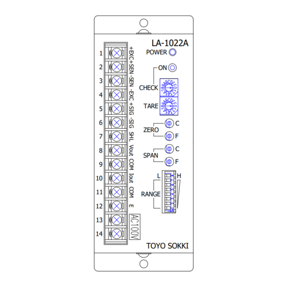
Applying voltage to Load Cell or a sensor is selected from 10V, 5V, 2.5V at the time of ordering. The power supplied voltage is AC100V as standard or DC24V which specified as option at the time of order. §2.Appearance and Each name Appearance of this unit LA-1022A POWER CHECK TARE ZERO SPAN... -
Page 4: 3.Operation
§3.Operation This unit outputs voltage signal and current signal. Voltage output is bipolar and can be output up to ±5V. (Max. ±10V depending on intensity of input signal from a sensor) Current output 4 ~20mA is available only when voltage output is set to 0~5V. Combination other than 4~20mA / 0~5V is impossible. -
Page 5: Adjustment Trimmer )
※Remind that amplification level is same at setting [GAIN MODE=H]、[RANGE (1~5)] and [GAIN MODE=L]、[RANGE (3~7)]. It means amplification range is in 9 steps in total. ※If output voltage is set to 10V, [GAIN MODE] should be set to H. Maximum load LC output of maximum load (mV/V)=... -
Page 6: Seudo Input Signal Setting Rotary Switch )
3-5) CHECK (Pseudo input signal setting rotary switch) (Pseudo input signal generating push switch) By pressing a [CHECK] button switch, a pseudo input signal can be generated and added to the input signal. A pseudo input signal is generated only while the button is pressed. The pseudo input signal can be set at about 0.15mV/V step by 16 position rotary switch. -
Page 7: 4.Calibration
§4.Calibration Calibrate the output level to 0V with no load on Load Cell, and calibrate the output level to the desired voltage with maximum load on Load Cell. Current output 4~20mA is available when voltage output is adjusted to 0~5V. Calibration operation is ba sed on “actual load calibration”... -
Page 8: 5.Troubleshooting
§5.Troubleshooting If this unit is malfunctioning, please contact us if the problem cannot be resolved by the following measures. At this time, please inform us of the model name, product serial number, the malfunction symptoms and usage as much as possible. The model name of Load Cell or a sensor connected to this unit should be also informed. -
Page 9: Udgement If This Unit Is Malfunction
② Tune a span adjustment trimmer to set current output to 20mA when output voltage is 5V Current output is adjusted properly at the shipment in TOYO factory. It is not necessary to re-adjust it. But current output is not appropriate even if re-adjusting has been done, please conta ct us. -
Page 10: 6.Installation And Connection Method
§6.Installation and connection method 6-1) Installation environment, etc. The operating temperature range of this unit is 0 ℃ to 40℃. Consider installing in a place not exposed the direct sunlight. This unit is operated with power supplied voltage AC100V±10%, or DC24V (DC20 to 27V) specified as option. -
Page 11: 7.List Of Models And Accessories
④ Since cable wiring color of Load Cell (transducer) differs depending on the manufacturer, check the wiring color with Test Report attached to Load Cell. ⑤ In general Load Cell, shield line of Load Cell cable is not connected to a metal case of Load Cell. -
Page 12: 8.Specifications
§8.Specifications 8-1) Power supply part to Load Cell or a sensor 1). Excitation Voltage DC10V±5% DC5V or DC2.5V is optional at the time of ordering. 2). Number of 4 sets of 350Ω type Load Cell (120mA maximum) Connectable sensors (EXC=5V: 60mA maximum, EXC=2.5V: 30mA maximum) 3). -
Page 13: Eneral
8-3) General 1). Power stability ±0.02% FS (Power supplied voltage fluctuation within±10%) 2). Power supplied AC100V±10% 50/60Hz as standard voltage DC24V (DC20~27V) as option 3). Current consumption approx. 10VA(AC100V), 0.5A typ.(DC24V) 4). Operating Temp./Humidity 0~+40℃、20~85% R.H. without condensation 5). Store Temp./Humidity 20~+60℃、20~85%... -
Page 14: 9.Dimensional Drawing
§9.Dimensional Drawing LA-1022A POWER CHECK TARE ZERO SPAN RANGE TOYO SOKKI §10.Functional block diagram AMPLIFICATION RANGE S1:x1 S2:x1.4 FREQUENCY SELECTION S3:x2 GAIN MODE S4:x2.8 S5:x4 S6:x5.6 S7:x8 Gain Adjustment Filter Tare subtraction Buffer Amplifier Voltage Output Zero adjustment SPAN Adjustment...
Need help?
Do you have a question about the LA-1022A and is the answer not in the manual?
Questions and answers