
Related Manuals for Sigalarm GENERATION 5 WIRELESS

Summary of Contents for Sigalarm GENERATION 5 WIRELESS
- Page 1 INSTALLATION OPERATION MANUAL GENERATION 5 WIRELESS sigalarminc.com • 01/12/2023 • version 6 • 1-800-589-3769 SIGALARM INSTALLATION AND OPERATION MANUAL / GENERATION 4 WIRELESS...
- Page 3 WITH PURCHASE ORDER • • • NOW AVAILABLE AT SIGALARMINC.COM/SHOP...
-
Page 4: Table Of Contents
6.2 Operating Procedures ......28 14.2 Canadian Compliance Statement..41 Information furnished by Allied Safety Systems Inc. DBA Sigalarm in this document is believed to be accurate. Allied Safety Systems Inc. makes no warranty, express, statutory and implied or by description, regarding the information set forth herein. - Page 5 READ THIS MANUAL IN ITS ENTIRETY BEFORE ATTEMPTING INSTALLATION OPERATION OPERATOR TRAINING ESSENTIAL SIGALARM OPERATOR TRAINING CLASSES ARE AVAILABLE THROUGH THE SIGALARM APP.
-
Page 6: Overview
The strength of the signal (E-field) depends on the lines’ voltage and the distance from the lines. Simple adjustment of the settings on the Sigalarm unit will provide accurate and repeatable warnings. After the desired setting is made, a visual and audible alarm will occur whenever the specified E-field (voltage) is detected. -
Page 7: Safety Warnings
It is the equipment operator’s responsibility to know and follow all OSHA, employer, utility, and equipment manufacturers’ instructions, rules, and regulations. NOT A DISTANCE MEASURING DEVICE Sigalarm products are warning systems and should not be used as distance measuring devices. 2. INSTALLATION 2.1 STANDARD PACKING LIST... -
Page 8: Installation Precautions
It can be installed one of two ways. SYNCHING WITH THE SIGALARM APP If you are using the Sigalarm Monitoring app (when available), scan the QR code on the back of the control module to synch it to your app. -
Page 9: Installation Of The Sensor(S)
5.0G5CMC, Grey Power cable - Black (Pin 8) Negative Ground *Note- wire colors might be different pin position is constant 2.5 INSTALLATION OF THE SENSOR(S); SIGALARM WS4.0 The solar sensors are the component of the system that detects voltage. TURN THE SENSOR ON: use external on/off power (red button) switch to turn unit on/off. - Page 10 PLACEMENT AND INSTALLATION: The almost unlimited type sizes and configurations of equipment on which Sigalarm products can be used, make it impossible to cover every potential installation configuration in the manual.
- Page 11 The distance between two sensors must not be greater than 1.75 x MAD. Distance between sensors cannot exceed 1.75 x MAD MINIMUM APPROACH DISTANCE - MAD EXAMPLE If MAD = 20’ Then 1.75 x 20’ = 35’ Distance between sensors < 35’ SIGALARM INSTALLATION AND OPERATION MANUAL / GENERATION 5 WIRELESS...
- Page 12 You must not rely on the information in this diagram as an alternative to advice from an appropriately qualified technician. If you have questions about any installation matter you should consult an appropriately qualified professional. PLACEMENT SUGGESTIONS SIGALARM INSTALLATION AND OPERATION MANUAL / GENERATION 5 WIRELESS...
-
Page 13: Installation Of The Speaker
5.0G5CMC as follows: 5.0G5CMC, Red (pin 11) to white horn conductor 5.0G5CMC, Black (pin 12) to black horn conductor EXTERNAL SPEAKER Do not mount this speaker inside a closed cab. SIGALARM INSTALLATION AND OPERATION MANUAL / GENERATION 5 WIRELESS... -
Page 14: Relay Options
2.7 RELAY OPTIONS Your Sigalarm has two relay options supplied with the 5.0G5CMC that allow you to customize your installation. These relays will open and close under different circumstances. A normal operation, warning, or danger status will open or close these relays according to the diagram. - Page 15 1 to the equipment’s hydraulics using Pin 6(red) and 1(black) so the circuit is interrupted and hydraulic movement is stopped in a danger status. *Auto shut down is never recommended for equipment moving a load* SIGALARM INSTALLATION AND OPERATION MANUAL / GENERATION 5 WIRELESS...
-
Page 16: Testing The Installation
Verify adjust the setpoint back to the that the external and internal desired level. speakers alarm. Also check that visual warnings on the control module are functioning. SIGALARM INSTALLATION AND OPERATION MANUAL / GENERATION 5 WIRELESS... -
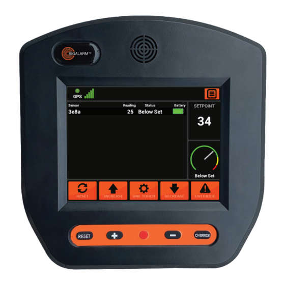
Page 17: Menu Display Identification
Tool bar ▶ Sensor dashboard ▶ Setpoint display ▶ Sensor status gauge ▶ Touch screen button icons You can swipe the screen to the left or right for alternate Gauge View. SIGALARM INSTALLATION AND OPERATION MANUAL / GENERATION 5 WIRELESS... -
Page 18: Tool Bar
3.2 TOOL BAR (REFER TO DIAGRAM ON PAGE 19) Top Tool Bar Function Indicates if the Sigalarm system is receiving GPS service Indicates GSM signal strength; Optional Menu This icon opens the Actions Screen 3.3 SENSOR DASHBOARD Sensor Dashboard Function... -
Page 19: Touch Screen Icons
The override icon can be selected in a danger state. This will put the unit in a warning state for 15 second countdown to allow the operator to move away from danger (*This is especially important when the auto shutdown feature is utilized*) SIGALARM INSTALLATION AND OPERATION MANUAL / GENERATION 5 WIRELESS... -
Page 20: Actions Screen Overview
The Actions Screen provides the point of access for all the following pages: ▶ Admin (password protected) ▶ Display Settings ▶ Setup Defaults ▶ Device info ▶ Manage Sensors (password protected) ▶ Volume Adjustment SIGALARM INSTALLATION AND OPERATION MANUAL / GENERATION 5 WIRELESS... -
Page 21: Admin
As an added layer of protection, access to these adjustments are password protected. PASSWORD Passwords should only be given to competent persons capable of making key safety decisions. SIGALARM INSTALLATION AND OPERATION MANUAL / GENERATION 5 WIRELESS... - Page 22 Disable alarm lockout is only relevant if the relay cable 1 is installed. For example, a customer could utilize the relays to install the Sigalarm in such a way that that the hydraulics are interrupted, and movement is stopped in a danger state.
- Page 23 Change Pin or Password: Tap the existing pin to change it, type in the new pin, select done to save it. All units will have a factory preset password of 0000. Sigalarm does not have access to the password once it has been changed.
-
Page 24: Display Setting
Sensors can be removed simply by selecting the icon. Sensors that are NOT paired will not report data to this control module. SIGALARM INSTALLATION AND OPERATION MANUAL / GENERATION 5 WIRELESS... - Page 25 REMOVING SENSORS To unpair a sensor in this list select the sensor by tapping it to reveal the menu, once the menu is displayed select the unpair icon, then select done. unpair SIGALARM INSTALLATION AND OPERATION MANUAL / GENERATION 5 WIRELESS...
-
Page 26: Manage Remotes
Item Action Screen Function Manage Remotes Pair remote Paired remotes will be listed in this screen. To pair new remotes select manage remotes, enter password, select pair new remote, follow the prompts. SIGALARM INSTALLATION AND OPERATION MANUAL / GENERATION 5 WIRELESS... -
Page 27: Duel Functionality
4.2 PROXIMITY ALARM Operators can choose to adjust the Sigalarm to provide warnings at a specific setpoint that is appropriate for that job site. 5. GETTING STARTED 5.1 INITIAL CONTROL MODULE SET UP... -
Page 28: Operation
Never approach any power line closer than the minimum safe distance set by OSHA. If multiple lines are present the Sigalarm system should be set to the lowest voltage line, and additional precautions may be required. -
Page 29: Adjusting The Setpoint
When adjusting the setpoint, always position the equipment far enough away from the power line to give the operator time to react. The Sigalarm system should be set to give a warning no closer than the minimum approach distance or MAD from the power line. Setpoint adjustments can also be made utilizing the increase or decrease buttons. -
Page 30: Sensor Reading
Do not operate equipment with a no data status. The system will beep alerting the operator of a no data status. See additional no data notes in the troubleshooting section. SIGALARM INSTALLATION AND OPERATION MANUAL / GENERATION 5 WIRELESS... -
Page 31: Field Operations
Sigalarm has internal relays that can be used in many different ways. Some employers install a Wireless Sigalarm in such a way that the equipment will stop moving in a Warning or Danger state. This is referred to as “Auto-Shutdown” and is a common installation technique. -
Page 32: Override Operating W/ Auto-Shutdown
9.7 OPERATING NEAR INTERSECTING LINES Intersecting lines, especially of different voltages, can create complex E-fields. Extreme caution should be taken when working around these conditions. Use additional layers of safety whenever appropriate possible. SIGALARM INSTALLATION AND OPERATION MANUAL / GENERATION 5 WIRELESS... -
Page 33: Override Feature
WARNING NOTES ▶ If multiple lines are present, the Sigalarm should be calibrated to the lowest voltage line, and additional preventative measures may need to be utilized. ▶ The operator MUST fully understand how the Sigalarm is installed, operates, and it’s limitations before use. -
Page 34: Data Management
7,200v AC. ▶ Sigalarm systems are not designed to detect DC voltage 11.5 RANGE OF EFFECTIVENESS Voltage Detection – Between 10 to 200 feet depending on voltage Zigbee Communication –... -
Page 35: Sensor Battery
Hold down the manual reset button for 15 seconds to force a “hard reboot”. ▶ Unplug the power cord for 60 seconds and restart. ▶ Call Sigalarm at 800-589-3769 for remote assistance if available. SIGALARM INSTALLATION AND OPERATION MANUAL / GENERATION 5 WIRELESS... -
Page 36: No Data
▶ The voltage may be too low to detect at that distance. ▶ The power line may be too far away for the sensor to detect at that voltage. SIGALARM INSTALLATION AND OPERATION MANUAL / GENERATION 5 WIRELESS... -
Page 37: Frozen Touch Screen
12.6 RADIO FREQUENCY INTERFERENCE Sigalarm has radio frequency filters built in. However, there are times that very strong signals can disrupt the normal functionality and make the Sigalarm alarm (for example near an airport). In this case you may want to change the frequency. -
Page 38: Intended Uses And Limitations
Are not intended to provide warning closer than 10ft to a power line. ▶ Are best used for detecting voltages at 7,200v. or greater. Relying solely on Sigalarm proximity alarms to detect lower voltages may result in warning too near the power source. ▶... - Page 39 (2) operating the equipment on sites with multiply overhead power lines, especially where those power lines had differing voltages or involved intersecting installations. SIGALARM INSTALLATION AND OPERATION MANUAL / GENERATION 5 WIRELESS...
-
Page 40: Regulatory Warnings
This equipment should be installed and operated with a minimum distance of 20cm between the radiator and all persons. This transmitter must not be co-located or operating in conjunction with any other antenna or transmitter. SIGALARM INSTALLATION AND OPERATION MANUAL / GENERATION 5 WIRELESS... -
Page 41: Canadian Compliance Statement
Toute modification de l’antenne ou de l’appareil pourrait avoir pour conséquence que l’appareil dépasse les exigences en matière d’exposition aux radiofréquences et annule le droit de l’utilisateur de faire fonctionner l’appareil. SIGALARM INSTALLATION AND OPERATION MANUAL / GENERATION 5 WIRELESS... - Page 42 NOTES:...
- Page 43 Customers wishing to return units to Sigalarm for any reason must complete the Return Material Authorization (RMA) form before returning the units. This includes both Warranty and Out of Warranty repairs. Send unit to 4150 St. Johns Pkwy, Ste 1002 Sanford FL 32771 Attn: Warehouse Service Technician.
- Page 44 WE’RE IN THE BUSINESS OF SAVING LIVES MADE IN USA sigalarminc.com • 01/12/2023 • version 6 • 1-800-589-3769...
Need help?
Do you have a question about the GENERATION 5 WIRELESS and is the answer not in the manual?
Questions and answers