Table of Contents
Advertisement
Quick Links
Technical Manual
for
ERI Model EC130
RF Dual Switch Controller
TM_EC130
June 30, 2022
Electronics Research, Inc. • 7777 Gardner Road • Chandler, IN 47610-9219 • USA
+1 812 925-6000 (tel) • +1 812 925-4030 (fax)
Your Single Source for Broadcast Solutions™ • Call Toll-free at 877 ERI-LINE • Visit Online at
www.eriinc.com
Advertisement
Table of Contents

Summary of Contents for Electronic Research Group EC130
- Page 1 Technical Manual ERI Model EC130 RF Dual Switch Controller TM_EC130 June 30, 2022 Electronics Research, Inc. • 7777 Gardner Road • Chandler, IN 47610-9219 • USA +1 812 925-6000 (tel) • +1 812 925-4030 (fax) Your Single Source for Broadcast Solutions™ • Call Toll-free at 877 ERI-LINE • Visit Online at...
-
Page 2: Technical Manual For Eri Model Ec130 Rf Switch Controller
Technical Manual for ERI Model EC130 RF Switch Controller Part Number: TM_EC130_RF_Switch_Controller Copyright 2022 by Electronics Research, Inc. Chandler, Indiana, USA No part of this publication may be reproduced, stored in a retrieval system, or transmitted, in any form or by any means - electronic, mechanical, recording, or otherwise - without the prior written permission of Electronics Research, Inc. -
Page 3: Table Of Contents
Technical Manual for ERI Model EC130 RF Switch Controller TM_EC130 Table of Contents Technical Manual for ERI Model EC130 RF Switch Controller ........2 Preface ........................... 5 Returns and Exchanges ....................5 Unpacking ........................5 Technical Assistance....................5 Purpose of this Manual....................5 Warning Regarding Personnel Risks ................ - Page 4 Technical Manual for ERI Model EC130 RF Switch Controller TM_EC130 Figure 7: Main Menu ..................... 13 Figure 8: Confirm Menu ....................14 Figure 9: Power Meter Menu ..................14 Figure 10: Power Meter Offset Menu ................15 Figure 11: Power Meter Offset Menu Example ............. 15 Figure 12: Power Meter Menu Example ................
-
Page 5: Preface
Technical Manual for ERI Model EC130 RF Switch Controller TM_EC130 Preface Returns and Exchanges Damaged or undamaged equipment should not be returned unless written approval and return authorization has been received from Electronics Research, Inc. Special shipping instructions and coding will be provided in said return authorization to assure proper handling. -
Page 6: Warning Regarding Personnel Risks
Technical Manual for ERI Model EC130 RF Switch Controller TM_EC130 understand its operation. In short, this manual is intended as a basic guide to the operation of the components described herein for specifically trained and qualified personnel only. Warning Regarding Personnel Risks Warning THE CURRENTS AND VOLTAGES IN THIS EQUIPMENT ARE DANGEROUS. - Page 7 Technical Manual for ERI Model EC130 RF Switch Controller TM_EC130 be prepared to give adequate Emergency First Aid and thereby prevent avoidable loss of life. Treatment of Electrical Burns 1. Extensive burned and broken skin • Cover area with cleanest available sheet or cloth.
-
Page 8: General Information
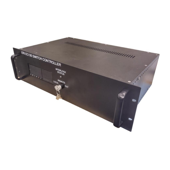
Electronics Research Inc. motorized RF dual switch controller. Switch Controller Description The EC130 motorized RF switch controller is designed to operate a two industrial standard motorized waveguide or coaxial RF switch. The controller is contained in a 5.23-inch standard 19-inch rack mountable chassis. The front panel, shown in figure 1 below, has a key-lock selector switch and a red/green LED that indicates the RF switch’s interlock status. -
Page 9: Rf Switch Requirements
Technical Manual for ERI Model EC130 RF Switch Controller TM_EC130 RF Switch Requirements The controller requires that the motorized RF switch DC voltage matches the controller DC voltage (either 12V or 24V available) The switch must have two form A (Normally Open Contact) limit switches in each of its two positions. -
Page 10: Installation
This section describes how to do this. READ BEFORE APPLYING POWER The EC130 is capable of 12Vdc or 24Vdc operation of two switches. It is not capable of controlling both a 12Vdc and a 24Vdc switch simultaneously. VERIFY the control voltage required by the switch intended to control and toggle the slide switch on the back panel to the appropriate voltage before powering the switch controller. -
Page 11: Wiring The Transmitter Interlock Circuit
Technical Manual for ERI Model EC130 RF Switch Controller TM_EC130 to be read at the EC130 which indicates the switch is connected. This is already in place if the EC200 Wiring harness is used with a “B” series ERI switch or an ERI “C”... -
Page 12: Figure 4: Switch Port Diagram (Shown In Position 2)
Technical Manual for ERI Model EC130 RF Switch Controller TM_EC130 Figure 4: Switch Port Diagram (Shown in position 2) Figure 5: Power Meter Pinout Connection Figure 6: Power Sample Placement Best Practice Page 12 of 28... -
Page 13: Operation
Technical Manual for ERI Model EC130 RF Switch Controller TM_EC130 Operation The operation of the EC130 switch controller is explained in this section. Front Panel Operation The front panel of the controller Menu Driven User Interface, a red/green LED and a 3- position switch-lock. -
Page 14: Figure 8: Confirm Menu
Technical Manual for ERI Model EC130 RF Switch Controller TM_EC130 The main screen shows the status for each switch. If a switch is not detected, and N/C (not connected) status will show in lieu of a switch position. Figure 8: Confirm Menu Pressing the “A”... -
Page 15: Figure 10: Power Meter Offset Menu
Technical Manual for ERI Model EC130 RF Switch Controller TM_EC130 Figure 10: Power Meter Offset Menu Pressing the “+” menu advance button again brings you to the offset menus for the power meters. If desired, the coupling value of the directional coupler or voltage probe can be added here to display a more accurate reading of power on the previous screen. -
Page 16: Figure 12: Power Meter Menu Example
If the level is set too low, the controller will not activate the switches, but if it is set too high the controller could switch under power. The EC130 will only activate a switch if the Interlock output is disengaged AND the power is below the selected threshold. -
Page 17: Snmp Network Configuration Setup
SNMP controller to update the firmware (Step 6). Flash the firmware in a short time after applying power to the EC130. If the power has been applied for some time, you may need to unplug the unit and plug it back in before being able to flash the new firmware. -
Page 18: Figure 14: Snmp Configuration Utility Main Interface
Technical Manual for ERI Model EC130 RF Switch Controller TM_EC130 Figure 14: SNMP Configuration Utility Main Interface Figure 15: Set Communication Default Network Parameters More detailed information on configuring the SNMP controller can be found at: http://www.adfweb.com/download/filefold/MN67164_ENG.pdf Page 18 of 28... -
Page 19: Table 1: Snmp Read Table
Technical Manual for ERI Model EC130 RF Switch Controller TM_EC130 SNMP Default settings IP Adress: 192.168.2.205 Subnet Mask: 255.255.255.0 Gateway: 192.168.2.1 Version READ Community public WRITE Community private Modbus (Do not modify) Serial: RS485 Baudrate: 9600 Parity: Even Timeout: 1000 ms... -
Page 20: Troubleshooting
5) Release the rail securing the converter to the enclosure for easier access. 6) There are two DIP switches facing towards the front of the EC130 Switch Controller, located on the same side as the Modbus 485 connections a. -
Page 21: Transmitter Interlock And Switch Motor Drive Control
Technical Manual for ERI Model EC130 RF Switch Controller TM_EC130 9) Apply power to the EC130 Switch Controller *Page 28 of the ADFWeb manual Transmitter Interlock and Switch Motor Drive Control To ensure that RF power is turned off before the motorized RF switch is operated and to further ensure that RF power is not applied to the switch before it has reached its commanded position the interlock circuit shown in Figure 16 is used. -
Page 22: Figure 17: Alternative Wiring Diagram Interlock Circuit
Technical Manual for ERI Model EC130 RF Switch Controller TM_EC130 regardless of the logic being supplied by the EC130 switch controller, thus preventing any accidental switching under RF power. Figure 17: Alternative Wiring Diagram Interlock Circuit Page 22 of 28... -
Page 23: Remote Control
Bypass Switch Controller The EC130 will provide Interlock logic only if a switch is detected. If no switch is detected, the Interlock will stay in an OFF logic condition as seen by the RED LED on the front panel. -
Page 24: Ec130 Accessories
Technical Manual for ERI Model EC130 RF Switch Controller TM_EC130 EC130 Accessories VDM303 Conic Power Detector, +20 dBm maximum input, 4-20 mA signal output, 24VDC power 1-5/8” EIA Coaxial Switch, 0 - 250 MHz CS250C 1-5/8” EIA Coaxial Switch, 470 - 860 MHz CS252C 3-1/8”... -
Page 25: Parts List And Drawings
Technical Manual for ERI Model EC130 RF Switch Controller TM_EC130 Parts List and Drawings Table 4: Parts List Page 25 of 28... -
Page 26: Figure 18: Drawing
Technical Manual for ERI Model EC130 RF Switch Controller TM_EC130 Figure 18: Drawing Page 26 of 28... -
Page 27: Figure 19: Ec130 Schematic
Technical Manual for ERI Model EC130 RF Switch Controller TM_EC130 Figure 19: EC130 Schematic Page 27 of 28... -
Page 28: Figure 20: Ec130-Pc1 Interface Board Schematic
Technical Manual for ERI Model EC130 RF Switch Controller TM_EC130 Figure 20: EC130-PC1 Interface Board Schematic Page 28 of 28...
Need help?
Do you have a question about the EC130 and is the answer not in the manual?
Questions and answers