Table of Contents
Advertisement
Quick Links
Advertisement
Table of Contents

Summary of Contents for RWT ENV120 Series
- Page 1 ENV120 Series SLUDGE BLANKET LEVEL METER...
- Page 2 SAFETY The ENV120 product is intended for use by qualified personnel PRECAUTIONS who recognize shock hazards and are familiar with the safety precautions required to avoid possible injury. Read the operating information carefully before using the product. Users of this product must be protected from electric shock at all times.
- Page 3 WESS Global, Inc. warrants the ultrasonic sludge blanket monitoring WARRANTY system, ENV120, to be free from defects in material or workmanship for a period of 1 year (12 months) from the date of this product was shipped from local distributors. A warranty claim will not be honored if defects are not reported within the warranty period, or if WESS Global, Inc.
-
Page 4: Table Of Contents
TABLE 1. PRODUCT DESCRIPTION…………………………………….5 OF CONTENTS 1.1 OVERVIEW 1.2 PROBE 1.3 CONTROLLER 1.4 CLEANING DEVICE 1.5 SWING BRACKET 2. APPLICATIONS……………………………………………….11 3. INSTALLATION…………………………..………...………..12 3.1 PROBE 3.2 CONTROLLER 3.3 CLEANING DEVICE 3.4 SWING BRACKET 4. POWER,WIRING & CONNECTIONS…......21 4.1 POWER REQUIREMENTS 4.2 PROBE WIRING 4.3 USER CONNECTIONS.. -
Page 5: Overview
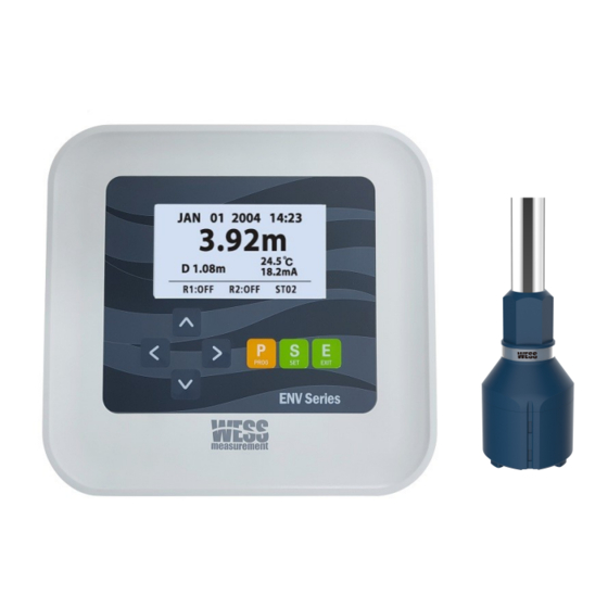
PRODUCT ENV120 series is a non-contacting ultrasonic instrument that DESCRIPTION measures the sludge blanket in series liquid. It consists of a probe and a firmware-driven controller. The firmware controls the ultrasonic probe and analyzes signals sent from the ultrasonic probe. (See Fig. 1) -
Page 6: Probe
PRODUCT The Fig.2 is an illustration of the ultrasonic probe S1T. DESCRIPTION PROBE(S1T) Fig.2 Probe(S1T) Specifications Material Body: PP Ultrasonic Head: PP Mounting Thread 3/4” PF thread Cable Length 10m or 33ft (STD.) Extendable to max. 100m Opera. Temp. -10 to 60°C (14 to 140°F) Dimensions Φ... - Page 7 PRODUCT The Fig.3 is an illustration of the ultrasonic probe S1G. DESCRIPTION PROBE(S1G) Fig.3 Probe(S1G) Specifications Material Body: STS304, STS316(Option) Ultrasonic Head: Epoxy Mounting Thread 3/4” PF male thread Cable Length 10m or 33ft (STD.) Extendable to max. 100m Oper. Temp. -10 to 60°C (14 to 140°F) Dimensions Φ...
-
Page 8: Controller
PRODUCT Fig.4 illustrates the controller DESCRIPTION CONTROLLER Fig.4 Controller Specifications Range 0.35 to 30m (1 to 33ft) Resolution 1cm (metric), 0.1ft (imperial) Accuracy ±0.5% of measured range or 1 inch, whichever is greater Oper. Temp. -20 to 70°C (-4 to 158°F) Outputs Current: 4 to 20mA, nom. -
Page 9: Cleaning Device
PRODUCT Max Altitude 2,000 m DESCRIPTION Max Humidity 80% (31℃) 50% (40°C ~ 60℃) Installation Category II – IEC644 Pollution Degree 2 – IEC644 CONTROLLER CE EMC Complies with EN61326 (Class A) EN61000, EN61010-1:2001 CLEANING DEVICE Fig.5 Cleaning Device Specifications Free Flow Rate 25L/min Max Pressure... -
Page 10: Swing Bracket
PRODUCT DESCRIPTION SWING BRACKET Fig.6 Swing bracket Specifications Material Probe Protector: STS 304 Probe Mounting Pipe: STS 304 Mounting Thread 3/4” PF male thread (Probe/user supply pipe) Damper Buffer Dimensions Damper : 85(W) x 100(H) Swing Bracket : 70(W) x 375(H) Weight Damper : 0.75 kg Swing Bracket : 0.40 kg... -
Page 11: Applications
APPLICATIONS The ENV120 is designed to monitor the levels of solid contents (sludge) in various types of liquids (water, liquor, etc.), to control the pumps engaged in the processes, and to initiate events based on measured process conditions. Some applications examples include: ... -
Page 12: Installation
INSTALLATION Do not inflict impact or unnecessary external force on the probe during handling. The ultrasonic head (see Fig .7), which transmits and receives sound waves, should be handled with extra care and stored wrapped in sponge or other soft materials to absorb the impact of an PROBE external blow. -
Page 13: Probe
INSTALLATION Refer to the Fig.8 to decide the depth of probe installation PROBE Fig.8 Stationary Installation of the Probe Fig.9 Probe Installation Structure (an example) REV4.0 ENV120 Sludge Blanket Monitoring System... - Page 14 INSTALLATION For tank or rectangular pool applications, maintain at least 1m of separation distance from the wall to minimize interference (see Fig.10 and Fig.11) and try to avoid a hopper area where the shape of sludge blanket varies upon pumping activity(see Fig.11) PROBE Fig.10 Minimum Separation Distance of Circular Clarifier Fig.11 Minimum Separation Distance of Rectangular Clarifier...
-
Page 15: Controller
INSTALLATION Protect the controller from impact and unnecessary external force until it is installed. Install the controller on a panel/handrail or wall using the mounting holes (Φ 6) located at the back of controller (see Fig.12). Schematic CONTROLLER diagram for U-bolt installation on a handrail is illustrated in Fig.13. Fig.12 Mounting Hole Position (Φ6 x 4ea) Fig.13 Handrail Installation Example REV4.0... - Page 16 INSTALLATION Located on the bottom of the controller are four cable glands the user can use selectively for his/her specific application (see Fig.14). Each cable gland should be connected using a cable of correct diameter (Φ 4.5 ~ 10mm) to ensure IP67 CONTROLLER Most products generally use the direct cable connection method, in which stripped wires connect directly to a terminal block (TB).
-
Page 17: Cleaning Device
INSTALLATION Use the female thread (M5) located at the rear to install the cleaning device on a panel/handrail (see Fig.15). Normally the cleaning device installs horizontally against the controller. Fig.16 illustrates a typical application using U-bolts. CLEANING DEVICE (OPTIONAL) Fig.15 Locations of Female Threads (M5 x 4ea) Fig.16 Handrail Mounting Example REV4.0 ENV120 Sludge Blanket Monitoring System... - Page 18 INSTALLATION Fig.17 illustrates the connection between the cleaning device and the probe / controller. Refer to Chapter 4 for detailed information of this electrical connection. CLEANING DEVICE Fig.17 connecting to enable the Cleaning Device REV4.0 ENV120 Sludge Blanket Monitoring System...
-
Page 19: Swing Bracket
INSTALLATION The swing bracket is used to protect the probe from damage caused by skimmer/scraper that exists at circular or rectangular clarifiers of the sewage treatment plant. ENV120’s swing bracket features a hinge damper that dampens the SWING BRACKET skimmer's impact during pendulum motions. (OPTIONAL) To connect the swing bracket to a probe, link the probe’s 3/4”... - Page 20 INSTALLATION SWING BRACKET Fig. 19 Typical Circular Clarifier Installation Fig. 20 Typical Rectangular Clarifier Installation CAUTION Take care not to damage a damper and a sensor protector by checking a surface skimmer’s direction REV4.0 ENV120 Sludge Blanket Monitoring System...
-
Page 21: Power,Wiring & Connections
POWER, WIRING AC 100 to 240V, 50/60Hz, < 15W Use copper conductors only. CONNECTIONS A user-supplied disconnect switch on a separate 15A circuit breaker should be located near the processor unit. Power line noise and interference are filtered by a built-in EMI filter. POWER WARNING REQUIREMENTS... -
Page 22: User Connections
POWER, WIRING The controller supports up to 5 parts of connections. Connections include Probe, mA and Serial Communication Outputs, CONNECTIONS Relay Output, Cleaning Device, and Power (see Fig.21). The controller accommodates up to 5 parts of connections. USER CONNECTIONS Fig.21 Connection Diagram REV4.0 ENV120 Sludge Blanket Monitoring System... -
Page 23: Probe Connection
POWER, WIRING he three respective colored wires from the probe cable to a Connect t 5-position PHOENIX connector and then put it into the PCB board CONNECTIONS (see Fig.22). PIN NO. PIN COLOR FUNCTION USER CONNECTIONS BLACK TX(Sensor) 4.3.1 PROBE(S1T) WHITE TEMP CONNECTION... - Page 24 POWER, WIRING he five respective colored wires from the probe cable to a 5- Connect t position PHOENIX connector and then put it into the PCB board (see CONNECTIONS Fig.23). PIN NO. PIN COLOR FUNCTION USER CONNECTIONS BLACK YELLOW 4.3.1 WHITE PROBE(S1G) BLUE(GREEN)
-
Page 25: Serial Connection
POWER, WIRING Serial communication (RS232/485) users may connect the serial wires to a 5-position PHOENIX connector and put it into the PCB CONNECTIONS board. The 5-position connector is composed of serial communication and analog output connections. The Fig.24 illustrates the serial communication part. -
Page 26: Analog Output
POWER, WIRING 4 to 20mA current output users may connect the wires to a 5-position PHOENIX type connector and put it into the PCB Board (see Fig.25). CONNECTIONS PIN NO. PIN NAME USER CONNECTIONS Table 4. Current Output Connection 4.3.3 ANALOG OUTPUT Fig.25 Analog Output Connection REV4.0... -
Page 27: Relay Output
POWER, WIRING Relay users may connect the wires to a 9-position PHOENIX type connector and put it into the PCB board (see Fig.26). CONNECTIONS Relay Rating: 250V AC, 5A USER PIN NO. PIN NAME FUNCTION CONNECTIONS 1-NO HIGH ON 1-COMMON COMMON 4.3.4 1-NC... -
Page 28: Cleaning Device
POWER, WIRING The cleaning device is activated using the controller’s power source. Connection is made using a 2-position PHOENIX connector (see CONNECTIONS Fig.27). Use AC power. USER CONNECTIONS PIN NO. PIN COLOR FUNCTION Line 4.3.5 Neutral CLEANING DEVICE Table 6. Cleaning device Connection Fig.27 Cleaning Device Connection REV4.0 ENV120 Sludge Blanket Monitoring System... -
Page 29: Power Coneection
POWER, WIRING An external power source (100 to 240V, 50 to 60Hz) activates the ENV120. Connection is made using a 3-position PHOENIX connector CONNECTIONS (see Fig.28). PIN NO. PIN NAME FUNCTION(AC) FUNCTION(DC) USER Line DC + CONNECTIONS Neutral DC - Ground 4.3.6. -
Page 30: Screens
SCREENS ENV120 features four types of visual screens: NUMERIC SCREEN, ECHO SCREEN, PARAMETER SCREEN, and DATA TREND SCREEN. When power is supplied, “Start…” prompts on the LCD before entering the Numeric Screen mode (see Fig.29). Fig. 29 Start-up Screen Fig. 30 Numeric Screen The Numeric Screen (refer to 5.1) displays some fundamental information, including... - Page 31 SCREENS The present measurement values appear when the power is supplied (see Fig.31). NUMERIC SCREEN Fig.31 Numeric Screen information Numeric Screen Values ① Present time for real time data logging(mm/dd/yy h:m) ② Sludge Level see Fig. 32 ③ Sludge Distance see Fig.
- Page 32 SCREENS The numeric screen mode described in 5.1 does not, however, provide form and size of reflected echo. The Echo screen offers this information to confirm the credibility of the values and to heighten measurement accuracy by inputting corrected value in field. ECHO SCREEN Fig.33 Echo screen This echo screen shows many values which help field operators.
- Page 33 SCREENS ECHO SCREEN Fig.34 VTA adjustment Pressing the ∧ or ∨ key under the Echo screen initiates VTA. When a dotted line with arrow appears, the value can be changed using the ∧ and ∨ keys. One press of each key is equivalent to ±5%.
- Page 34 SCREENS The parameter screen displays some important parameters to check brief field condition. The parameters of this screen are Empty, Dead Zone, 4/20mA, Echo Amp, ASF, Offset, Test Mode, and Density. Table 8 explains parameters and its functions. PARAMETER SCREEN Fig.35 Parameter Screen Parameter Function...
-
Page 35: Data Trend Screen
SCREENS ENV120 offers data trend screen mode to complement its 10,000- point data logging function. Under this mode, the user can check the data trend (time/blanket level) and residual memory points through a graph (see Fig.36) DATA TREND SCREEN Fig.36 Data Trend Screen The value of graph is sludge blanket level and selected data logging time scale. -
Page 36: Screen Switching
SCREENS SCREENS SWITCHING Fig.37 Screen Switching Key Operation (>), (<) : Switch between four screens E(EXIT) : Return to previous screen(On the Data trend screen) S(SET) : Switch to Data trend screen(continued for more than 3 seconds) REV4.0 ENV120 Sludge Blanket Monitoring System... -
Page 37: Menu System
MENU SYSTEM The following section describes menu system navigation and parameter selections. The front panel of ENV120 contains 7 membrane keys and a graphic BASIC LCD display. These keys are used to navigate through the menu KEY OPERATION system, allowing the user to operate ENV120 with ease (see Fig.38). Fig.38 Front Panel Keys and Functions PROG... - Page 38 MENU SYSTEM The program mode consists of five menu sections. The user can access the program mode by pressing the PROG key. (see Fig.39) OVERVIEW OF MENU SYSTEM Fig.39 Main menu access Main menu section consists of System, Relay, Complement, Data Logging, Complement, and Service menu section.
-
Page 39: Overview Of Menu System
MENU SYSTEM OVERVIEW OF MENU SYSTEM Fig.41 Submenu Access Each menu setting is saved on a built-in non-volatile memory every time and return to operation mode. (see Fig.41) Fig.42 Return to Operation Mode REV4.0 ENV120 Sludge Blanket Monitoring System... - Page 40 MENU SYSTEM General functions of the menu sections are: SYSTEM Basic parameter settings OVERVIEW Parameter unit and operation OF MENU SYSTEM Tank depth of measurement site and Dead zone Relationship between level and current output Log on/off Firmware’s version Language RELAY Relay parameter settings High, low relay parameter...
-
Page 41: System Menu Options
MENU SYSTEM The system menu section, which contains operation and measurement output menu options, is essential for the operation of ENV120. Menu options of this section are System Unit, Operation, Empty, Dead Zone, 4mA, 20mA, Log on/off, Protocol, Time, SW. SYSTEM Version, and Language. - Page 42 MENU SYSTEM SYSTEM MENU OPTIONS Fig.43 System Menu Overview REV4.0 ENV120 Sludge Blanket Monitoring System...
- Page 43 MENU SYSTEM Table 10 lists menu options and range of their set values. MAIN SUBMENU FUNCTION PARAMETER Meter System SYSTEM Operation Unit Unit Feet MENU OPTIONS Output and Level Operation measurement value Distance Distance between the probe’s surface Empty 0.00 ~ 10.00 and container’s bottom Dead...
-
Page 44: Relay Menu Options
MENU SYSTEM This section is used when ENV120 operates with external actuators such as a pump, a motor, etc. When an alarm is required in field, user sets its parameter in this section. The key setting method is the same as 6.3.system menu section. - Page 45 MENU SYSTEM MAIN SUBMENU FUNCTION PARAMETER High level alarm R1 Act 0.00 ~ 10.00m RELAY on(see Fig.40) MENU OPTIONS High level alarm R1 Stop 0.00 ~ 10.00m off( (see Fig.40) Low level alarm on R2 Act 0.00 ~ 10.00m (see Fig.40) Relay Low level alarm R2 Stop...
- Page 46 MENU SYSTEM Fig.45 illustrates the example of relay setting and Fig.46 shows the operational status of R1 and R2. RELAY MENU OPTIONS Fig.45 Relay Setting Fig.46 Operational Status REV4.0 ENV120 Sludge Blanket Monitoring System...
-
Page 47: Datalogging Menu Options
MENU SYSTEM This section is used for field data monitoring and analysis. Menu options of this section include Download, Delete, Data Interval, and Display Term. The Fig.47 illustrates the menu options and Table 12 lists menu options of this section. DATALOGGING MENU OPTIONS Fig.47 Data Logging Menu Overview... - Page 48 MENU SYSTEM MAIN SUBMENU FUNCTION PARAMETER Download DATALOGGING Download Yes/No data MENU OPTIONS Delete Delete Yes/No data Data Logging Data 1/10/60min Interval 1min 12/24hrs Display 10min 24hrs/7days Term 60min 14/30days Table 12 Logging Menu Options 1. This option determines the data logging interval. After setting the desired value, ENV120 informs the maximum data saving period.
-
Page 49: Complement Menu Options
MENU SYSTEM This complement menu section is used for enhancing measurement credibility and precision. Menu options of this section include Clean Interval, Clean Term, Damping, Threshold, ASF ON/OFF, and Density. Fig.48 illustrates the menu option composition and Table 13 lists COMPLEMENT menu options of this section. - Page 50 MENU SYSTEM MAIN SUBMENU FUNCTION PARAMETER Operational interval of COMPLEMENT Clean Interval 0 sec ~ 100 min cleaning MENU OPTIONS device Term(period) Clean Term of cleaning 0 ~ 100 sec each time Weighting Complement ratio of 1 sec ~ 60 min Damping measurement Voltage value...
-
Page 51: Rs232/485
RS232/485 The data format of RS232/485 is the same as below. Data Format Fig. 49 Data Format Data frame is composed of 20 bytes. D: Distance S: Sludge Level T: Temperature E: Error code The unit of distance and sludge level is in meter. Ex) Meter: 0323 ... -
Page 52: System Repair And Return
SYSTEM REPAIR For spare parts or technical assistance, please contact your local AND RETURN WESS representative or contact WESS Service department. WESS Service Department E-mail : sales@wessglobal.com CUSTOMER Adress : B-8F, Ace high-tech city, 10 Baekseockgongdan 1-ro, ASSISTANCE Seobuk-gu, Cheonan, 31094, Korea REPAIR AND All systems or probes returned for repair or replacement must have RETURN POLICY...
Need help?
Do you have a question about the ENV120 Series and is the answer not in the manual?
Questions and answers