
Summary of Contents for UniGuard UT04S
- Page 1 GPS Integrated Speed Limiter Technician Manual UniGuard GPS Speed Governor Road Speed Limiter for Transportation Safety Technician Manual version2.3 Model No: UT04S A Product of UniGuard Technology Limited...
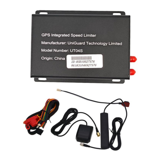
- Page 2 1 Brief Production GPS integrated speed limiter UT04S is a combination of speed governor and GPS tracking technology. With GPS and GSM, user can track and monitor their vehicle real time by both Web and Phone application. With connection of pulse wire, it can accurately control vehicle driving speed so as to ensure safe driving.
- Page 3 2 GPS speed limiter Features Speed Limiter Enforce to limit the speed of your vehicle if preset maximum speed 2 Tamper proof Maximum speed is 40km/h if maximum speed is tampered or sensor is cut. 3 Download data Data can be retrieved by connecting device to computer via CDC data port 4 Portable Printer Violations can be printed out for the last one-hour driving.
- Page 4 3 GPS speed limiter Specifications Name UT04S GPS Speed Limiter Weight 191g Dimension 110*75*30 mm Working voltage DC 9V-36V Backup battery 800mAh 3.7V Battery working time 12hrs Working current 42mAh/12V Standby current 16mA Charging current Max < 500mA Input Fuse Working power Working Temp.
- Page 5 4 GPS speed limiter interface...
- Page 6 ACC (Orange): connected to vehicle ACC wire to detect engine ON/OFF PULSE(Purple): connected to vehicle speed signal wire to detect speed GND / DC+ (Red and Black): connected to battery positive and ground. NC (GREEN): 24V/12V to 0V output wire. Normal speed, 24V/12V; Over speed, 0V. Connection: Cut off fuel pump power wire, connect GREEN wire to the pump side cut...
- Page 7 5 SMS Command List Usage Command Comment or Reply To send command, Password command must be sent first Check Location <CXWZ,> Replay Google map link Restart device <RES=0,> Check setup and <CXIP,> <P,APN=etc.com,MTN=20208103731,SLM=T, firmware version MIP=www.gpspos.net:8800,BIP=www.gpspos.n et:8800,0X,VER=TM-STACL/EA2AS- TMKJG04P2 Sep 28 2020/21:07:58,> Check status <CXEI,>...
- Page 8 6 External Optional accessory connection 1 Mechanical actuator: Limiter NC ( GREEN) connect with actuator Green signal wire. Actuator has 3 wires. Red for battery Positive+, Yellow for Ground. Green is signal wire. Connect limiter GREEN wire to actuator Green wire, the steel rope shall reach out around 5CM, disconnect device Yellow wire, the steel rope shall pull...
- Page 9 Pedal controller installation: 1 Find the vehicle pedal harness, it is composed of 6 wires, 2 wire is the signal wires, 2 wire is power wire, 2 wire is ground wire. Start the vehicle, step on the pedal, make vehicle at idle state, voltage at signal wire shall change. 2 Cut off the 2 signal wires, and then connect respectively the pedal controller wire.
- Page 10 7 PC config tool By connection device to computer via 4 PIN COM port, user can setup and read device details as below. Limiter serial is device ID, please do not change it. Usage: 1 Connect device with to computer, choose the right COM (here is COM3) 2 Fill in data except Limiter serial 3 Click Setup to config 4 Click Read to read config data...
- Page 11 8 Portable Printer Printing Connect device to printer, turn on Printer, printing shall start in few secs. Use printer COM port to print 9 Data Display Use cable below to connect with device and computer. Device mut be connected, otherwise SSCOM cannot show port. Use this cable for using SSCOM tool...
- Page 12 10 Device Speed Limit and Pulse efficient setup. Speed limit setup, Open SSCOM tool, send VSET,80; Pulse coefficient setup, Open tool, send PPK,2000; (if we know a vehicle pulse coefficient, same type of vehicle pulse coefficient should be same.)
- Page 13 11 Device Pulse Coefficient calibration Output data explanation, Open tool, send DEBUG=1; (Please run vehicle at 20KM/H and send this data, so as to check if data are all right) 10.0,18.0,17.9,2000,0,80 10,0 Current pulse number, unit is Hz 18.0 Current pulse speed, unit is KM/H 17.9 Current running speed, unit is KM/H 2000, pulse coefficient 0, GPS speed, unit is KM/H...
- Page 14 12 Geo-fence based Speed Limit In order to limit vehicle speed per different areas, user can draw fence (Round, Rectangle, or Polygon) at the web monitoring software so as to limit vehicle speed at different valve per real environment. For example, at urban area, set speed limit at 60KM/H; at suburb area, set speed limit at 80KM/H.
- Page 15 13 Web and APP usage Web tracking software login: www.gpsops.net APP: Android phones please search POSGPS at Google Play, IOS phones search GPSPOS at Appstore Main Features: 1. Create / Edit / Delete / Distribute subaccount 2. Create / Edit / Delete / Distribute device 3.
- Page 16 15 Speed Limit and Pulse Speed Value Display on Web...
Need help?
Do you have a question about the UT04S and is the answer not in the manual?
Questions and answers