Advertisement
Quick Links
SERVO MOTOR CONTROLLER
60-300 VDC, RS 232, ANALOG 4-20 MA, CAN OPEN
NOTICE: THIS DOCUMENT WAS EXPORTED FROM THE UNITED STATES IN ACCORDANCE WITH THE EXPORT
ADMINISTRATION REGULATIONS. DIVERSION CONTRARY TO U.S. LAW IS PROHIBITED.
NOTICE: PROPRIETARY INFORMATION OF WHITTAKER CONTROLS, INC., A BUSINESS UNIT OF MEGGITT PLC.
THE INFORMATION CONTAINED IN THIS DOCUMENT IS DISCLOSED IN CONFIDENCE. IT IS THE PROPERTY OF
WHITTAKER CONTROLS, AND SHALL NOT BE USED, DISCLOSED TO OTHERS, OR REPRODUCED IN WHOLE
OR IN PART WITHOUT THE EXPRESS WRITTEN CONSENT OF WHITTAKER CONTROLS. IF CONSENT IS GIVEN
THIS NOTICE SHALL APPEAR IN ANY SUCH REPRODUCTION.
Maintenance Manual
PART NUMBERS:
REVISION 1.0 – 07/01/2005
C159980
C159980-1
C159980-2
Advertisement

Summary of Contents for Whittaker C159980
- Page 1 THE INFORMATION CONTAINED IN THIS DOCUMENT IS DISCLOSED IN CONFIDENCE. IT IS THE PROPERTY OF WHITTAKER CONTROLS, AND SHALL NOT BE USED, DISCLOSED TO OTHERS, OR REPRODUCED IN WHOLE OR IN PART WITHOUT THE EXPRESS WRITTEN CONSENT OF WHITTAKER CONTROLS. IF CONSENT IS GIVEN THIS NOTICE SHALL APPEAR IN ANY SUCH REPRODUCTION.
-
Page 2: Table Of Contents
WHITTAKER CONTROLS, INC. A MEGGITT PLC COMPANY MAINTENANCE MANUAL SERVO MOTOR CONTROLLER – MODEL C159980 LIST OF EFFECTIVE PAGES On a revised page, the portion of text or illustrations affected by the change is indicated by a vertical line in the outer margin of the page. When a revision is issued, the entire document is reissued with the current revision number and date shown on all pages. - Page 3 WHITTAKER CONTROLS, INC. A MEGGITT PLC COMPANY MAINTENANCE MANUAL SERVO MOTOR CONTROLLER – MODEL C159980 LIST OF APPENDICES APPENDIX NUMBER OF PAGES DS2000 Servodrive User’s Manual, Section 6 – Commands ....23 Installation Drawing, CA24635 .
- Page 4 WHITTAKER CONTROLS, INC. A MEGGITT PLC COMPANY MAINTENANCE MANUAL SERVO MOTOR CONTROLLER – MODEL C159980 USE APPROVED SAFETY EQUIPMENT ! When cleaners are being used, approved explosion-proof lights, blowers, and other equipment must be used. Make sure that fire fighting equipment is readily available and in working order.
-
Page 5: Introduction
WHITTAKER CONTROLS, INC. A MEGGITT PLC COMPANY MAINTENANCE MANUAL SERVO MOTOR CONTROLLER – MODEL C159980 INTRODUCTION Purpose of Manual This manual provides component maintenance shop instructions for the Servo Motor Controller (con- troller). Scope of Manual This manual is intended to provide information in sufficient detail to permit proper fault isolation main- tenance, and repair of the controller. -
Page 6: Description And Operation
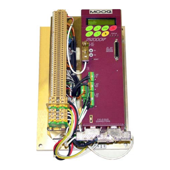
WHITTAKER CONTROLS, INC. A MEGGITT PLC COMPANY MAINTENANCE MANUAL SERVO MOTOR CONTROLLER – MODEL C159980 DESCRIPTION AND OPERATION Description The Servo Motor Controller (see Figure 1) is installed remotely from the valve it controls, in its own explosion proof container or in a separate customer furnished cabinet. In either case, the controller must be located within 600 feet (182 meters) wire run length from the valve. - Page 7 WHITTAKER CONTROLS, INC. A MEGGITT PLC COMPANY MAINTENANCE MANUAL SERVO MOTOR CONTROLLER – MODEL C159980 Figure 1. Servo Motor Controller Revision 1.0 07/01/2005 Page 7 INDUSTRIAL PRODUCTS GROUP...
-
Page 8: Envelope Dimensions
WHITTAKER CONTROLS, INC. A MEGGITT PLC COMPANY MAINTENANCE MANUAL SERVO MOTOR CONTROLLER – MODEL C159980 Figure 2. Envelope Dimensions Revision 1.0 07/01/2005 Page 8 INDUSTRIAL PRODUCTS GROUP... - Page 9 WHITTAKER CONTROLS, INC. A MEGGITT PLC COMPANY MAINTENANCE MANUAL SERVO MOTOR CONTROLLER – MODEL C159980 The motor transducer can be both a resolver (2 to 24 poles) and an incremental encoder (1024 to 8192 pulses). Command Interface Appendix A contains information on the commands available from the keypad on the controller’s front panel.
-
Page 10: Servo Motor Controller
WHITTAKER CONTROLS, INC. A MEGGITT PLC COMPANY MAINTENANCE MANUAL SERVO MOTOR CONTROLLER – MODEL C159980 Specifications/Characteristics (Refer to Table 1) Table 1. Servo Motor Controller Specifications/Characteristics Type ..........Analog control with digital interface Temperatures Operating Ambient . - Page 11 WHITTAKER CONTROLS, INC. A MEGGITT PLC COMPANY MAINTENANCE MANUAL SERVO MOTOR CONTROLLER – MODEL C159980 INSTALLATION General This section and the installation drawing in Appendix C contain information on installation of the controller in the system. Installation Electrical Interfaces Tag Out and Lock Out! Be sure that power is off prior to touching any electrical wires! Hard wiring to terminal strips, conduit, conduit connectors.
- Page 12 WHITTAKER CONTROLS, INC. A MEGGITT PLC COMPANY MAINTENANCE MANUAL SERVO MOTOR CONTROLLER – MODEL C159980 Special Cable Capacitance Requirements The customer cable connecting the resolver on the valve to the controller must have a capa- citance of 40 pf/foot maximum, wire-to-wire, and a capacitance of 80 pf/foot maximum wire-to- shield.
- Page 13 MAINTENANCE MANUAL SERVO MOTOR CONTROLLER – MODEL C159980 APPENDIX A DS2000 SERVODRIVE USER’S MANUAL SECTION 6 – COMMANDS NOTE: THE SERVODRIVE IS MODIFIED BY WHITTAKER CON- TROLS TO MEET PERFORMANCE REQUIREMENTS. THE SERVODRIVE IS NOT FIELD REPAIRABLE. Revision 1.0 07/01/2005...
- Page 14 Section 6: Commands DS2000 Servodrive User’s Manual GB-4534 Rev. 8 06/04...
- Page 15 SECTION SIX – COMMANDS 6. COMMANDS 6.1. INTRODUCTION The six keys on the drive front panel allow the visualization of the whole menu as well as the relevant drive con- figuration. A further key allows the display contrast adjustment. The keys can be divided according to their function: •...
- Page 16 SECTION SIX – COMMANDS 6.2. MOTOR PARAMETERS MENU Fig. 6.2 – Motor parameters menu 6.2.1. MOTOR PARAMETERS MENU DESCRIPTION Description: it indicates the number of motor poles MOTOR PARAMETERS POLES= Note: set the values indicated on the nameplate of Allowed values: from 2 to 24 in 2 unit steps the motor or refer to the data indicated on the mo- tor catalogue.
- Page 17 SECTION SIX – COMMANDS Description: it indicates the nominal motor speed MOTOR PARAMETERS SPEED= Note: set the values indicated on the nameplate of Allowed values: from 100 rpm to 9999 rpm in 10 rpm steps the motor or refer to the data indicated on the mo- tor catalogue Description: it indicates the motor generated back- MOTOR PARAMETERS BEMF=...
- Page 18 SECTION SIX – COMMANDS Description: it indicates the starting speed for the INI PHASE SHIFT= G motors algorithm, to improve phase shift at high speed mainly for motors having 8-12 poles and rotating over 3000 rpm Note: see related application notes for additional Allowed values: from 100 to max speed drive in 10 unit steps details...
- Page 19 SECTION SIX – COMMANDS 6.3. DRIVE PARAMETERS MENU Fig. 6.3 – Drive parameters menu 6.3.1. DRIVE PARAMETERS MENU DESCRIPTION Description: it indicates drive address for serial DRIVE ADDRESS DRVADDR= communication Note: set a progressive and different value per Allowed values: from 1 to 62 each drive to obtain only one serial line to interro- gate all the drives existing in the machine...
- Page 20 SECTION SIX – COMMANDS Description: it indicates NTC/PTC threshold value PTCNTC THRESHOLD= used to protect motor from overtemperature Note: set following value for Moog motor: Allowed values: • from 100 Ω to 10000 Ω in 1 unit steps 1200 Ω for PTC thermal feedback •...
- Page 21 SECTION SIX – COMMANDS Description: enable I2T protection on IGBT if out- I2T IGBT PROTECT put frequency is lower than 5kHz Note: enabling I2T IGBT PROTECT, NOTCH FIL- Allowed values: • 0 (for disabled) TER will be automatically disabled • 1 (for enabled) Note: when this protection is active, the letters I2T will appear on the main window (Moog DS2000) menu...
- Page 22 SECTION SIX – COMMANDS Description: it allows to reverse the motor rotation ROTATION= direction on the same applied reference signal Allowed values: Note: • CW (right) • CCW (left) Description: it allows to limit the max motor speed MAX. SPEED= at a lower value than the one set in the motor pa- rameters Note: Input analog reference remains diminished at...
- Page 23 SECTION SIX – COMMANDS Description: it allows to select the max input refer- MAX.INPUT REFER.= ence value in order to reach the max speed set Note: set the selected value on the numeric control Allowed values: from 3.2 V to 10.0 V in 0.1 V unit steps to obtain a direct correspondence Attention: function available only with analog ref- erence...
- Page 24 6.10 SECTION SIX – COMMANDS Description: it allows to limit the speed reference SPEED REF.FILTER= band through of a low-pass digital filter Note: filter allows to limit the motion overshoots Allowed values: from 1 Hz to 800 Hz in 1 unit steps due to sudden variations of the reference signal Description: it allows to limit the speed reference SPEED ERR.FILTER=...
- Page 25 6.11 SECTION SIX – COMMANDS 6.5. DRIVE ENABLE MENU Fig. 6.5 – Drive enable menu 6.5.1. DRIVE ENABLE MENU DESCRIPTION Description: it allows to control the drive if in the DRIVE ENABLE DRIVE PARAMETER menu the DRIVE ENABLE is set in LOCAL mode Allowed values: Note: •...
- Page 26 6.12 SECTION SIX – COMMANDS Description: it indicates the DC BUS voltage de- BUS VOLTAGE tected by the drive; this value is used for the soft start and recovery circuit management Description: it indicates the +15 V voltage de- +15 VOLTAGE tected by the drive Description: it indicates the -15 V voltage detected -15 VOLTAGE...
- Page 27 6.13 SECTION SIX – COMMANDS 6.7. UTILITY MENU Fig. 6.7.1 – Utility parameters menu, part I Fig. 6.7.2 – Utility parameters menu, part II 6.7.1. CONFIGURATION ANALOG OUT MENU DESCRIPTION When this menu is accessed the preset value is shown, use < or > keys to scroll the menu then press ENTER to select the required value and exit.
- Page 28 6.14 SECTION SIX – COMMANDS Description: Analog Out is configured as the cur- |CURRENT REF. | rent reference module. The information can be use- ful to check the real load applied both by the drive and the motor Description: Analog Out is configured as the cur- ILIMIT rent analog limit set.
- Page 29 6.15 SECTION SIX – COMMANDS 6.7.2. SAVE PARAMETERS MENU DESCRIPTION It allows to save drive configuration parameters inside the flash memory. The drive must be disabled. Press ENTER to enable this function; the following messages are shown automatically on display: •...
- Page 30 6.16 SECTION SIX – COMMANDS 6.7.4. PHASING MENU DESCRIPTION CAUTION: in this phase the motor can rotate for a revolution fraction, it is recommended to make sure it is free to rotate to avoid risk of friction, which could compromise phasing accuracy. If this message appear on the display, rotate the ADJUST ENCODER FOR TRIGGER motor shaft until the message changes...
- Page 31 6.17 SECTION SIX – COMMANDS 6.8. KEYBOARD LOCK MENU Fig. 6.8 – Fault detection menu 6.8.1. KEYBOARD LOCK MENU DESCRIPTION Description: it allows to unlock the keyboard and KEYBOARD LOCK change the drive parameters Allowed values: Note: • LOCKED • UNLOCKED DS2000 USER’S MANUAL...
- Page 32 6.18 SECTION SIX – COMMANDS 6.9. FAULT DETECTION MENU Fig. 6.9 – Fault detection menu 6.9.1. FAULT DETECTION MENU DESCRIPTION TROUBLESHOOTING Section can provide to give additional information about Faults. Description: it detects the excess current or short IGBT FAULT U PHASE/HS circuit condition of the output IGBT three-phase bridge Description: it detects the excess current or short...
- Page 33 6.19 SECTION SIX – COMMANDS Description: it detects the excess current or short IGBT FAULT W PHASE/HS circuit condition of the output IGBT three-phase bridge Description: it detects the excess current or short IGBT FAULT U PHASE/LS circuit condition of the output IGBT three-phase bridge Description: it detects the excess current or short IGBT FAULT V PHASE/LS...
- Page 34 6.20 SECTION SIX – COMMANDS Description: it indicates an error in the internal FLASH-ERROR DEFAULT SETTING reading of the parameters memorized inside the drive; it is possible a reading error in the internal memory. Try to switch the drive off and cut off the line.
- Page 35 6.21 SECTION SIX – COMMANDS Description: it indicates an internal memory error; FLASH ERROR CHECKSUM try to switch the drive off in order to verify the memory is correctly read and to save all data again after a further check. In case the problem persists, the internal memory is damaged Description: it indicates that the IGBT protection IGBT FAULT I2T PROTECTION...
- Page 36 WHITTAKER CONTROLS, INC. A MEGGITT PLC COMPANY MAINTENANCE MANUAL SERVO MOTOR CONTROLLER – MODEL C159980 APPENDIX B INSTALLATION DRAWING CA24635 Revision 1.0 07/01/2005 Appendix B INDUSTRIAL PRODUCTS GROUP...
Need help?
Do you have a question about the C159980 and is the answer not in the manual?
Questions and answers