
Related Manuals for Sourcetronic ST600 Series


Summary of Contents for Sourcetronic ST600 Series
- Page 1 SOURCETRONIC – Quality electronics for service, lab and production User Manual ST600 Series Frequency Inverter...
- Page 2 Preface Thank you for choosing the ST600 series high-performance multifunction VFD. The frequency inverter ST600 series VFD is a high-performance and multipurpose VFD aiming to integrate the driving of synchronous motors and asynchronous motors, and torque control, speed control with position control. It is armed with advanced vector control technology and the latest digital processor dedicated to motor control, thus enhancing product reliability and adaptability to the environment.
-
Page 3: Table Of Contents
Frequency Inverter ST600 Series High-Performance Multifunction VFD Contents Contents Preface ..........................i Contents ..........................ii 1 Safety Precautions ......................1 1.1 What this chapter contains ..................1 1.2 Safety definition ......................1 1.3 Warning symbols ...................... 1 1.4 Safety guidelines ...................... 2 1.4.1 Delivery and installation ................. - Page 4 Frequency Inverter ST600 Series High-Performance Multifunction VFD Contents 4.5.3 Protect motor and prevent thermal overload ..........39 4.5.4 Bypass connection ..................39 5 Basic Operation Instructions ..................40 5.1 What this chapter contains ..................40 5.2 Keypad introduction ....................40 5.3 Keypad display .......................
- Page 5 Frequency Inverter ST600 Series High-Performance Multifunction VFD Contents P03––Vector control of motor 1 ................147 P04––V/F control ....................152 P05––Input terminals ..................158 P06––Output terminals ..................165 P07––HMI ......................169 P08––Enhanced functions .................. 174 P09––PID control ....................181 P10––Simple PLC and multi-step speed control ..........185 P11––Protection parameters ................
- Page 6 Frequency Inverter ST600 Series High-Performance Multifunction VFD Contents 7.7.2 Interference on communication ..............269 7.7.3 Failure to stop and indicator shimmering due to motor cable coupling ..270 7.7.4 Leakage current and interference on RCD ..........270 7.7.5 Live device chassis ..................271 8 Maintenance and hardware fault diagnosis ..............
- Page 7 Frequency Inverter ST600 Series High-Performance Multifunction VFD Contents A.8.1 4G card (SIC502-2-CN, SIC502-2-EU, SIC502-2-LA) ......... 340 Appendix B Technical data ..................... 341 B.1 What this chapter contains ................... 341 B.2 Derated application ....................341 B.2.1 Capacity ....................341 B.2.2 Derating ..................... 341 B.3 Grid specifications ....................
-
Page 8: Safety Precautions
Frequency Inverter ST600 Series High-Performance Multifunction VFD Safety Precautions 1 Safety Precautions 1.1 What this chapter contains Read this manual carefully and follow all safety precautions before moving, installing, operating and servicing the VFD. If these safety precautions are ignored, physical injury or death may occur, or there may be damage to the equipment. -
Page 9: Safety Guidelines
Frequency Inverter ST600 Series High-Performance Multifunction VFD Safety Precautions 1.4 Safety guidelines Only trained and qualified electricians are allowed to carry out related operations. ⚫ Do not perform wiring, inspection or component replacement when a power supply is ⚫ connected. Ensure all the input power supplies are disconnected before wiring and inspection, and wait for at least the time designated on the VFD or until the DC bus voltage is less than 36V. -
Page 10: Commissioning And Running
Frequency Inverter ST600 Series High-Performance Multifunction VFD Safety Precautions the input power cables and motor cables properly; otherwise damage to the VFD may occur. 1.4.2 Commissioning and running Disconnect all power sources applied to the VFD before terminal wiring, and wait for at ⚫... -
Page 11: Maintenance And Component Replacement
Frequency Inverter ST600 Series High-Performance Multifunction VFD Safety Precautions 1.4.3 Maintenance and component replacement Only well-trained and qualified professionals are allowed to perform maintenance, ⚫ inspection, and component replacement on the VFD. Disconnect all the power sources applied to the VFD before terminal wiring, and wait ⚫... -
Page 12: Precautions For Quick Application
2.2 Unpack inspection Check as follows after receiving products. Check whether the packing box is damaged or dampened. If yes, contact local sellers or Sourcetronic offices. Check the model identifier on the exterior surface of the packing box is consistent with the purchased model. -
Page 13: Installation Confirmation
Frequency Inverter ST600 Series High-Performance Multifunction VFD Precautions for Quick Application Check whether ambient temperature of the VFD during actual application is below -10°C, if yes, install a heating facility. Note: For a cabinet-type VFD, its ambient temperature is the air temperature inside the cabinet. -
Page 14: Basic Commissioning
Frequency Inverter ST600 Series High-Performance Multifunction VFD Precautions for Quick Application 2.6 Basic commissioning Carry out basic commissioning according to the following procedures before operating on the VFD. Select motor type, set motor parameters and select VFD control mode according to actual motor parameters. -
Page 15: Product Overview
Frequency Inverter ST600 Series High-Performance Multifunction VFD Product Overview 3 Product Overview 3.1 What this chapter contains This chapter mainly introduces the operation principles, product features, layouts, nameplates and model instructions. 3.2 Basic principle The frequency inverter ST600 high-performance multifunction VFD is used to control asynchronous AC induction motor and permanent-magnet synchronous motor. - Page 16 Frequency Inverter ST600 Series High-Performance Multifunction VFD Product Overview Figure 3-3 Main circuit diagram for standard model VFDs 045G3–110G3 Figure 3-4 Main circuit diagram for standard model VFDs 132G3 and above (+) DC reactor (-) Figure 3-5 Main circuit diagram for SP model VFDs 018G3–110G3 Note: 1.
-
Page 17: Product Specification
Frequency Inverter ST600 Series High-Performance Multifunction VFD Product Overview 3. Built-in brake units are included in the SP model VFDs and standard model VFDs 037G3 and below. The models that carry built-in brake units can also be connected to external brake resistors. The brake resistors are optional parts. - Page 18 Frequency Inverter ST600 Series High-Performance Multifunction VFD Product Overview Keeps running with regenerative energy when the grid Retension at transient voltage drop transiently drops. Supports two groups of motor parameters to control motor Motor switchover switchover. Terminal analog input No more than 20mV...
-
Page 19: Product Nameplate
Frequency Inverter ST600 Series High-Performance Multifunction VFD Product Overview 3.4 Product nameplate Figure 3-6 Product nameplate Note: This is an example of the nameplate of standard frequency inverter ST600 products. The UKCA/CE/IP20/IP55 markings on the top right will be marked according to actual product model and certification conditions. -
Page 20: Rated Values
Frequency Inverter ST600 Series High-Performance Multifunction VFD Product Overview 3.6 Rated values Table 3-2 Rated values of standard models Output Input Output Frame Product model power current current code (kW) ST600-1R5G3 ST600-2R2G3 13.5 ST600-004G3 19.5 ST600-5R5G3 18.5 ST600-7R5G3 ST600-011G3 ST600-015G3 18.5... - Page 21 Frequency Inverter ST600 Series High-Performance Multifunction VFD Product Overview Table 3-3 Rated values of SP models Input Frame Output power Output Product model current code (kW) current (A) ST600SP-004G3 13.5 ST600SP-5R5G3 19.5 ST600SP-7R5G3 18.5 ST600SP-011G3 ST600SP-015G3 ST600SP-018G3 18.5 ST600SP-022G3 ST600SP-030G3...
-
Page 22: Structure Diagram
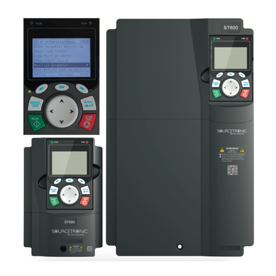
Frequency Inverter ST600 Series High-Performance Multifunction VFD Product Overview 3.7 Structure diagram The VFD layout is shown in the figures below. Figure 3-8 Structure diagram of standard models (using a 030G3 VFD as an example) Name Upper cover Used to protect internal components. - Page 23 Frequency Inverter ST600 Series High-Performance Multifunction VFD Product Overview Figure 3-9 Structure diagram of SP models (using a 015G3 VFD as an example) Name Upper cover Protects internal components and parts For details, see section 5.4 "Operating the VFD through the Keypad keypad"...
-
Page 24: Installation Guide
⚫ regulations. Sourcetronic does not assume any liability whatsoever for any installation which breaches local laws and regulations. If recommendations given by Sourcetronic are not followed, the VFD may experience problems that the warranty does not cover. 4.2 Mechanical installation 4.2.1 Installation environment... -
Page 25: Installation Direction
Frequency Inverter ST600 Series High-Performance Multifunction VFD Installation Guide install the VFD on combustible objects like wood). Away from radioactive substances and combustible objects. ⚫ Away from corrosive liquid. ⚫ Low salt content. ⚫ No direct sunlight. ⚫ Below 1000m. -
Page 26: Installation Mode
Frequency Inverter ST600 Series High-Performance Multifunction VFD Installation Guide 4.2.3 Installation mode The VFDs can be installed in several different modes, depending on the model: Figure 4-3 Installation modes of the standard model VFDs For the standard models, there are three kinds of installation modes depending on the different VFD dimensions: •... -
Page 27: Single-Unit Installation
Frequency Inverter ST600 Series High-Performance Multifunction VFD Installation Guide Installation: (1) Mark the position of the installation hole. See Appendix C "Dimension drawings" for the position of the installation hole; (2) Mount the screws or bolts onto the designated position;... -
Page 28: Multiple-Unit Installation
Frequency Inverter ST600 Series High-Performance Multifunction VFD Installation Guide 4.2.5 Multiple-unit installation Figure 4-7 Parallel installation (standard models) Hot air Cold air Figure 4-8 Parallel installation (SP models) Hot air Cold air Note: 1. When users install VFDs in different sizes, align the top of each VFD before installation for the convenience of future maintenance. -
Page 29: Vertical Installation
Frequency Inverter ST600 Series High-Performance Multifunction VFD Installation Guide 4.2.6 Vertical installation Figure 4-9 Vertical installation (standard models) Windshield Cold Cold Windshield Note: During vertical installation, users must install a windshield, otherwise the VFD will experience mutual interference, and the heat dissipation effect will be degraded. - Page 30 Frequency Inverter ST600 Series High-Performance Multifunction VFD Installation Guide Figure 4-10 Vertical installation (SP models) Note: During vertical installation, users must install a windshield, otherwise the VFD will experience mutual interference, and the heat dissipation effect will be degraded. -23-...
-
Page 31: Tilted Installation
Frequency Inverter ST600 Series High-Performance Multifunction VFD Installation Guide 4.2.7 Tilted installation Figure 4-11 Tilted installation (standard models) Note: During tilted installation, it is a must to ensure the air inlet duct and air outlet duct are separated from each other to avoid mutual interference. - Page 32 Frequency Inverter ST600 Series High-Performance Multifunction VFD Installation Guide Figure 4-12 Tilted installation (SP models) Note: During tilted installation, it is a must to ensure the air inlet duct and air outlet duct are separated from each other to avoid mutual interference.
-
Page 33: Standard Wiring Of Main Circuit
Frequency Inverter ST600 Series High-Performance Multifunction VFD Installation Guide 4.3 Standard wiring of main circuit 4.3.1 Wiring diagram of main circuit Figure 4-13 Main circuit wiring diagram of standard model VFDs Braking resistor (+) (-) Output reactor Input 037G3 and lower... - Page 34 Frequency Inverter ST600 Series High-Performance Multifunction VFD Installation Guide Figure 4-14 Main circuit wiring diagram of SP model VFDs Note: 1. The fuse, brake unit, brake resistor, input reactor, input filter, output reactor and output filter are optional parts. See Appendix D "Optional peripheral accessories" for details.
-
Page 35: Main Circuit Terminal Diagram
Frequency Inverter ST600 Series High-Performance Multifunction VFD Installation Guide 4.3.2 Main circuit terminal diagram Figure 4-15 Main circuit terminal diagram for standard model VFDs 022G3 and below Figure 4-16 Main circuit terminal diagram for standard model VFDs 030G3–037G3 Figure 4-17 Main circuit terminal diagram for standard model VFDs 045G3–110G3 Figure 4-18 Main circuit terminal diagram for standard model VFDs 132G3–200G3... - Page 36 Frequency Inverter ST600 Series High-Performance Multifunction VFD Installation Guide Figure 4-19 Main circuit terminal diagram for standard model VFDs 220G3–315G3 Figure 4-20 Main circuit terminal diagram for standard model VFDs 355G3–500G3 -29-...
- Page 37 Frequency Inverter ST600 Series High-Performance Multifunction VFD Installation Guide Terminal Name Sign Function description Standard model Standard model Standard model 037G3 and lower 045G3–110G3 132G3 and higher 3PH AC input terminal, R, S, T Main circuit power input connected to the grid.
- Page 38 Frequency Inverter ST600 Series High-Performance Multifunction VFD Installation Guide Figure 4-21 Main circuit terminal diagram for SP model VFDs 004G3–5R5G3 Figure 4-22 Main circuit terminal diagram for SP model VFDs 7R5G3–015G3 With AC input switch Without AC input switch NS :...
- Page 39 Frequency Inverter ST600 Series High-Performance Multifunction VFD Installation Guide Figure 4-23 Main circuit terminal diagram for SP model VFDs 018G3–022G3 With AC input switch Without AC input switch NS : Figure 4-24 Main circuit terminal diagram for SP model VFDs 030G3–037G3...
- Page 40 Frequency Inverter ST600 Series High-Performance Multifunction VFD Installation Guide Figure 4-26 075G3–110G3 Sign Terminal name Function description Main circuit power input 3PH AC input terminal, connect to the grid R, S, T VFD output 3PH AC output terminal, connect to the motor...
-
Page 41: Wiring Process Of The Main Circuit Terminals
Frequency Inverter ST600 Series High-Performance Multifunction VFD Installation Guide 4.3.3 Wiring process of the main circuit terminals 1. Connect the grounding line of the input power cable to the grounding terminal (PE) of the VFD, and connect the 3PH input cable to R, S and T terminals and tighten up. -
Page 42: Standard Wiring Of Control Circuit
Frequency Inverter ST600 Series High-Performance Multifunction VFD Installation Guide 4.4 Standard wiring of control circuit 4.4.1 Wiring diagram of basic control circuit Figure 4-28 Wiring diagram of control circuit Forward running Analog output Forward jogging 0-10V/0-20mA Fault reset output HDIA... - Page 43 Frequency Inverter ST600 Series High-Performance Multifunction VFD Installation Guide Terminal name Instruction +10V The VFD provides +10.5V power 1. Input range: AI1 voltage/current can choose 0–10/ 0–20mA; AI2: -10V–+10V voltage; 2. Input impedance: 20kΩ during voltage input; 250Ω during current input;...
-
Page 44: Input/Output Signal Connection Diagram
Frequency Inverter ST600 Series High-Performance Multifunction VFD Installation Guide Max. input frequency: 50kHz; Duty ratio: 30%–70%; HDIB Supports the input of a quadrature encoder with 24V power supply; equipped with speed- measurement function +24V—H1 STO input 1 1. Safe torque off (STO) redundant input, connect to external NC contact, STO acts when the contact opens, and the VFD stops output;... -
Page 45: Wiring Protection
Frequency Inverter ST600 Series High-Performance Multifunction VFD Installation Guide on the power used according to the figure below. Figure 4-31 NPN mode If input signal comes from PNP transistor, set the U-shaped jumper based on the power used according to the figure below. -
Page 46: Protect The Motor And Motor Cable In Short Circuit
Frequency Inverter ST600 Series High-Performance Multifunction VFD Installation Guide Figure 4-34 Fuse configuration (SP models) Input cable Fuse Note: Select the fuse according to operation manual. During short-circuit, the fuse will protect input power cables to avoid damage to the VFD; when internal short-circuit occurred to the VFD, it can protect neighboring equipment from being damaged. -
Page 47: Basic Operation Instructions
This chapter tells users how to use the VFD keypad and the commissioning procedures for common functions of the VFD. 5.2 Keypad introduction LCD keypad is included in the standard configuration of ST600 series VFDs. Users can control the VFD start/stop, read state data and set parameters via keypad. Figure 5-1 Keypad diagram (standard models) - Page 48 Frequency Inverter ST600 Series High-Performance Multifunction VFD Basic Operation Instructions Note: 1. The LCD keypad is equipped with a real-time clock, which can run properly after power off when installed with batteries. The clock battery (type: CR2032) should be purchased by the user separately.
- Page 49 Frequency Inverter ST600 Series High-Performance Multifunction VFD Basic Operation Instructions The function of confirmation key varies with menus, Confirmation e.g. confirming parameter setup, confirming parameter selection, entering the next menu, etc. Under keypad operation mode, the running key is Running key used for running operation or autotuning operation.
-
Page 50: Keypad Display
VFD is in jogging state; "Pre-alarm"–the VFD is under pre-alarm state during running; "Fault"–VFD fault occurred. Header C VFD model display area Display VFD model: "ST600 – current VFD is ST600 series VFD Parameter names and Display a maximum of three parameter names and function codes... -
Page 51: Displaying Running-State Parameters
Frequency Inverter ST600 Series High-Performance Multifunction VFD Basic Operation Instructions is the main interface during power-up by default. In stopped state, parameters in various states can be displayed. Press to shift the displayed parameter up or down. Figure 5-4 Stopped-state parameter display 1... -
Page 52: Displaying Fault Information
Frequency Inverter ST600 Series High-Performance Multifunction VFD Basic Operation Instructions Figure 5-7 Running-state parameter display 2 In running state, multiple kinds of state parameters can be displayed. The running display parameter list is user defined, and each state variable function code can be added to the running display parameter list as needed. - Page 53 Frequency Inverter ST600 Series High-Performance Multifunction VFD Basic Operation Instructions Figure 5-10 Enter/exit menu diagram 2 16:02:35 Forw ard Forw ard F orw ard Local R eady 01: ST600 16:02:35 Local R eady 16:02:35 Local R eady 01: ST600 01: ST600...
- Page 54 Frequency Inverter ST600 Series High-Performance Multifunction VFD Basic Operation Instructions The keypad menu setup is shown as follows. Level 1 Level 2 Level 3 Level 4 P00.xx P00: Basic Function P01.xx P01: Start/stop control P03.xx P03: Motor1 Vector Ctrol P04.xx P04: V/F Control P07.xx...
- Page 55 Frequency Inverter ST600 Series High-Performance Multifunction VFD Basic Operation Instructions User defined Pxx.xx parameters P07: HMI P07.xx P17: State Viewing Func P17.xx State monitoring P18: CI-IpCtrlStateView P18.xx parameters P19: Ex-card StateView P19.xx P93: Tension control state P93.xx viewing func P07.27: TypeofLatelyFault P07.28: Typeof1stLastFault...
-
Page 56: Editing A Parameter List
Frequency Inverter ST600 Series High-Performance Multifunction VFD Basic Operation Instructions Download motor func para from keypad Upload local func para to keypad Download all func para from keypad MemArea2: BACKUP012 Download NonMotor func para from keypad Download motor func para... -
Page 57: Adding Parameters To The Parameter List Displayed In Stopped/Running State
Frequency Inverter ST600 Series High-Performance Multifunction VFD Basic Operation Instructions Figure 5-11 List edit diagram 1 16:02:35 Forward Local Ready 01: ST600 16:02:35 Forward 01: ST600 16:02:35 Forward 01: ST600 Local Ready Local Ready Parameter displayed in stop state Shift up P17.00: Set frequency... -
Page 58: Adding Parameters To The User Defined Parameter List
Frequency Inverter ST600 Series High-Performance Multifunction VFD Basic Operation Instructions Figure 5-14 Adding parameter diagram 1 1 6 :0 2 :3 5 1 6 :0 2 :3 5 1 6 :0 2 :3 5 F o rw a rd L o c a l... -
Page 59: Editing User Defined Parameters
Frequency Inverter ST600 Series High-Performance Multifunction VFD Basic Operation Instructions parameter setup list menu. All the function code groups under the parameter group menu can be added to the user defined parameter list. Up to 64 function codes can be added to the user defined parameter list. -
Page 60: Monitoring States
Frequency Inverter ST600 Series High-Performance Multifunction VFD Basic Operation Instructions Figure 5-17 Editing parameters in parameter groups A uthority: √ A uthority: √ 16:02:35 Forw ard Local R eady 01: ST600 C urrent value: 50.00 C urrent value: 50.00 M ax. output frequency M ax. -
Page 61: Backing Up Parameters
Frequency Inverter ST600 Series High-Performance Multifunction VFD Basic Operation Instructions Figure 5-19 Selecting a parameter autotuning type 16:02:35 Forw ard Local R eady 01: ST600 16:02:35 Forw ard Local R eady 01: ST600 16:02:35 Forw ard Local R eady C om plete param eter rotary autotuning... -
Page 62: Power-On Setup Wizard
Frequency Inverter ST600 Series High-Performance Multifunction VFD Basic Operation Instructions Figure 5-22 System setting diagram Forward Local Ready 16:02:35 01: ST600 16:02:35 Forward Local Ready 01: ST600 Common parameter setup Language selection Parameter setup Time/date State monitoring Backlight brightness adjustment... -
Page 63: Basic Operation Instruction
Frequency Inverter ST600 Series High-Performance Multifunction VFD Basic Operation Instructions Auth: √ Default: 0 Present: 0 0:简体中文 1:English 2:Русский язык (Reserve) 3:Português (Reserve) 4:Español (Reserve) 5:Italiano (Reserve) Back Home Sele Auth: √ Default: 0 Present: 0 0: Always 1: Only once... -
Page 64: Common Commissioning Procedures
Frequency Inverter ST600 Series High-Performance Multifunction VFD Basic Operation Instructions 5.5.2 Common commissioning procedures The common operation procedures are shown below (take motor 1 as an example). Start Power up after confirming the wiring is correct Restore to default values... - Page 65 Frequency Inverter ST600 Series High-Performance Multifunction VFD Basic Operation Instructions Multi-function terminal Multi-function terminal Multi-function terminal Current running function (36) function (37) function (38) command channel Command switches to Command switches to Command switches to P00.01 keypad terminal communication Keypad...
- Page 66 Frequency Inverter ST600 Series High-Performance Multifunction VFD Basic Operation Instructions 0: No operation 1: Restore to default value 2: Clear fault records 3: Reserved 4: Reserved 5: Restore default values (for factory test mode) Function parameter P00.18 6: Restore default values (including motor...
-
Page 67: Vector Control
The ST600 Series VFD carries built-in speed sensor-less vector control algorithm, which can be used to drive the asynchronous motor and permanent-magnet synchronous motor simultaneously. As the core algorithm of vector control is based on accurate motor parameter model, the accuracy of motor parameters will impact the control performance of vector control. - Page 68 Frequency Inverter ST600 Series High-Performance Multifunction VFD Basic Operation Instructions Function Default Name Description code value 0: SVC 0 1: SVC 1 2: SVPWM Speed control mode P00.00 3: FVC Note: If 0, 1 or 3 is selected, it is required to carry out motor parameter autotuning first.
- Page 69 Frequency Inverter ST600 Series High-Performance Multifunction VFD Basic Operation Instructions Brake slip compensation 50%–200% P03.08 100% coefficient of vector control Current loop proportional 0–65535 P03.09 1000 coefficient P Current loop integral 0–65535 P03.10 1000 coefficient I 0:Disable P03.32 Torque control enable 1:Enable 0: Keypad (P03.12)
- Page 70 Frequency Inverter ST600 Series High-Performance Multifunction VFD Basic Operation Instructions Source of upper limit 0: Keypad (P03.17) P03.15 frequency setup of reverse 1–11: the same as P03.14 rotation in torque control Keypad limit value of upper P03.16 50.00Hz limit frequency of forward rotation in torque control Value range: 0.00 Hz–P00.03 (max.
-
Page 71: Svpwm Control Mode
Frequency Inverter ST600 Series High-Performance Multifunction VFD Basic Operation Instructions 0–0x1111 Ones place: Torque command selection 0: Torque reference 1: Torque current reference Tens place: Reserved 0: Reserved 1: Reserved Control optimization setting P03.35 0x0000 Hundreds place: Whether to enable ASR... - Page 72 Frequency Inverter ST600 Series High-Performance Multifunction VFD Basic Operation Instructions The VFD also provides multi-point V/F curve. Users can alter the V/F curve outputted by VFD through setting the voltage and frequency of the three points in the middle. The whole curve consists of five points starting from (0Hz, 0V) and ending in (fundamental motor frequency, rated motor voltage).
- Page 73 Motor oscillation often occurs in SVPWM control in large-power drive applications. To solve this problem, the ST600 Series VFD sets two function codes to control the oscillation factor, and users can set the corresponding function code based on the occurrence frequency of oscillation.
- Page 74 Frequency Inverter ST600 Series High-Performance Multifunction VFD Basic Operation Instructions Customized V/F curve (V/F separation) function: When selecting customized V/F curve function, users can set the reference channels and acceleration/deceleration time of voltage and frequency respectively, which will form a real-time V/F curve through combination.
- Page 75 Frequency Inverter ST600 Series High-Performance Multifunction VFD Basic Operation Instructions Function Default Name Description code value 0: SVC 0 1: SVC 1 2: SVPWM P00.00 Speed control mode 3: FVC Note: If 0, 1 or 3 is selected, it is required to carry out motor parameter autotuning first.
- Page 76 Frequency Inverter ST600 Series High-Performance Multifunction VFD Basic Operation Instructions Low-frequency oscillation 0–100 P04.10 control factor of motor 1 High-frequency oscillation 0–100 P04.11 control factor of motor 1 Oscillation control threshold 0.00Hz–P00.03 (max. output frequency) P04.12 30.00Hz of motor 1 0: Straight V/F curve;...
- Page 77 Frequency Inverter ST600 Series High-Performance Multifunction VFD Basic Operation Instructions 0: Keypad; output voltage is determined by P04.28 1: AI1 2: AI2 3: AI3 4: HDIA 5: Multi-step 6: PID P04.27 Channel of voltage setup 7: Modbus/Modbus TCP communication 8: PROFIBUS/CANopen communication...
- Page 78 Frequency Inverter ST600 Series High-Performance Multifunction VFD Basic Operation Instructions When the synchronous motor VF control mode is enabled, this parameter is used to set the Frequency threshold for frequency threshold for the switching between input injection current switching in P04.36...
-
Page 79: Torque Control
Frequency Inverter ST600 Series High-Performance Multifunction VFD Basic Operation Instructions Starting frequency point for P04.44 10.00Hz switching off IF mode for 0.00–P04.50 asynchronous motor 1 0: Disable Enable/disable IF mode for P04.45 asynchronous motor 2 1: Enable When IF control is adopted for asynchronous... - Page 80 Frequency Inverter ST600 Series High-Performance Multifunction VFD Basic Operation Instructions -73-...
- Page 81 Frequency Inverter ST600 Series High-Performance Multifunction VFD Basic Operation Instructions Function Default Name Description code value 0: SVC 0 1: SVC 1 2: SVPWM P00.00 Speed control mode 3: FVC Note: If 0, 1 or 3 is selected, it is required to carry out motor parameter autotuning first.
- Page 82 Frequency Inverter ST600 Series High-Performance Multifunction VFD Basic Operation Instructions Source of upper limit frequency setup of 0: Keypad (P03.17) P03.15 reverse rotation in 1–11: the same as P03.14 torque control Keypad limit value of upper limit frequency of P03.16 0.00Hz–P00.03 (max.
-
Page 83: Motor Parameter
Disconnect the load to carry out autotuning if necessary. The ST600 Series VFD can drive asynchronous motors and synchronous motors, and it supports two sets of motor parameters, which can be switched over by multi-function digital input terminals or communication modes. - Page 84 Frequency Inverter ST600 Series High-Performance Multifunction VFD Basic Operation Instructions Ready P00.01=0 (controlled by keypad) Synchronous Asynchronous Motor type motor motor (P02.00) P02.00=1 P02.00=0 Input motor nameplate Input motor nameplate (P02.15–P02.19) (P02.01–P02.05) Set autotuning mode (P00.15) Complete parameter Complete parameter...
- Page 85 Frequency Inverter ST600 Series High-Performance Multifunction VFD Basic Operation Instructions Related parameter list: Function Default Name Description code value 0: Keypad P00.01 Running command channel 1: Terminal 2: Communication 0: No operation 1: Rotary autotuning 1; carry out comprehensive motor parameter autotuning;...
- Page 86 Frequency Inverter ST600 Series High-Performance Multifunction VFD Basic Operation Instructions Mutual inductance of Model- P02.09 0.1–6553.5mH asynchronous motor 1 dependent No-load current of Model- P02.10 0.1–6553.5A asynchronous motor 1 dependent Rated power of synchronous Model- P02.15 0.1–3000.0kW motor 1 dependent Rated frequency of P02.16...
- Page 87 Frequency Inverter ST600 Series High-Performance Multifunction VFD Basic Operation Instructions Rated power of asynchronous Model- P12.01 0.1–3000.0kW dependent motor 2 Rated frequency of P12.02 50.00Hz 0.01Hz–P00.03 (max. output frequency) asynchronous motor 2 Rated speed of asynchronous P12.03 1–36000rpm motor 2 Rated voltage of P12.04...
-
Page 88: Start/Stop Control
Frequency Inverter ST600 Series High-Performance Multifunction VFD Basic Operation Instructions 5.5.7 Start/stop control The start/stop control of the VFD is divided into three states: start after running command at power- up; start after restart-at-power-cut function is effective; start after automatic fault reset. Descriptions for these three start/stop control states are presented below. - Page 89 Frequency Inverter ST600 Series High-Performance Multifunction VFD Basic Operation Instructions 1. Logic diagram for running command after power-up -82-...
- Page 90 Frequency Inverter ST600 Series High-Performance Multifunction VFD Basic Operation Instructions 2. Logic diagram for restart after power-cut -83-...
- Page 91 Frequency Inverter ST600 Series High-Performance Multifunction VFD Basic Operation Instructions 3. Logic diagram for restart after automatic fault reset Related parameter list: Function Default Name Description code value 0: Keypad P00.01 Running command channel 1: Terminal 2: Communication Model- P00.11 Acceleration time 1 0.0–3600.0s...
- Page 92 Frequency Inverter ST600 Series High-Performance Multifunction VFD Basic Operation Instructions after stop Waiting time of DC brake after P01.10 0.00–50.00s 0.00s stop P01.11 DC brake current of stop 0.0–100.0% 0.0% P01.12 DC brake time of stop 0.00–50.00s 0.00s Deadzone time of P01.13...
- Page 93 Frequency Inverter ST600 Series High-Performance Multifunction VFD Basic Operation Instructions Deceleration time of P01.26 2.0s 0.0–60.0s emergency-stop Time of starting section of P01.27 0.1s 0.0–50.0s deceleration S curve Time of ending section of P01.28 0.0–50.0s 0.1s deceleration S curve P01.29 Short-circuit brake current 0.0–150.0% (of the rated VFD output current)
-
Page 94: Frequency Setup
Frequency Inverter ST600 Series High-Performance Multifunction VFD Basic Operation Instructions Model- P08.04 Acceleration time 4 0.0–3600.0s dependent Model- P08.05 Declaration time 4 0.0–3600.0s dependent 0.00–P00.03 (max. output frequency) Switching frequency of 0.00Hz: No switch over P08.19 acceleration/deceleration time If the running frequency is larger than P08.19, switch to acceleration /deceleration time 2 0: Max. - Page 95 Frequency Inverter ST600 Series High-Performance Multifunction VFD Basic Operation Instructions The VFD supports switch-over between different reference channels, and the rules for channel switch- over are shown below. Multi-function terminal Multi-function terminal Multi-function terminal Present reference function 13 function 14...
- Page 96 Frequency Inverter ST600 Series High-Performance Multifunction VFD Basic Operation Instructions Note: "/" indicates this multi-function terminal is invalid under present reference channel. When setting the auxiliary frequency inside the VFD via multi-function terminal UP (10) and DOWN (11), users can increase/decrease the frequency quickly by setting P08.45 (UP terminal frequency incremental change rate) and P08.46 (DOWN terminal frequency decremental change rate).
- Page 97 Frequency Inverter ST600 Series High-Performance Multifunction VFD Basic Operation Instructions Reference object of B 0: Max. output frequency P00.08 frequency command 1: A frequency command 0: A 1: B Combination mode of setup 2: (A+B) P00.09 source 3: (A-B) 4: Max (A, B)
-
Page 98: Analog Input
Frequency Inverter ST600 Series High-Performance Multifunction VFD Basic Operation Instructions 5.5.9 Analog input ST600 Series VFD carries two analog input terminals (AI1 is 0–10V/0–20mA (voltage input or current input can be set by P05.50); AI2 is -10–10V) and two high-speed pulse input terminals. Each input can be filtered separately, and the corresponding reference curve can be set by adjusting the reference corresponds to the max. - Page 99 Frequency Inverter ST600 Series High-Performance Multifunction VFD Basic Operation Instructions Corresponding setting of P05.27 -300.0%–300.0% 100.0% upper limit of AI1 P05.28 Input filter time of AI1 0.000s–10.000s 0.100s P05.29 Lower limit value of AI2 -10.00V–P05.31 -10.00V Corresponding setting of lower P05.30...
-
Page 100: Analog Output
Frequency Inverter ST600 Series High-Performance Multifunction VFD Basic Operation Instructions Corresponding setting of P05.48 -300.0%–300.0% 100.0% upper limit frequency of HDIB HDIB frequency input filter 0.000s–10.000s 0.030s P05.49 time 0–1 P05.50 AI1 input signal type 0: Voltage type 1: Current type 5.5.10 Analog output... - Page 101 Frequency Inverter ST600 Series High-Performance Multifunction VFD Basic Operation Instructions Output voltage 0–1.5 times of rated voltage of VFD Output power 0–Twice the rated power of motor 0–Twice the motor rated current. A Set torque value negative value corresponds to 0.0% by default.
- Page 102 Frequency Inverter ST600 Series High-Performance Multifunction VFD Basic Operation Instructions Set value 2 of EtherCAT/PROFITNET/Ethernet IP 0–1000 communication AO1 from the Programmable card 0–1000 AO2 from the Programmable card 0–1000 0–Twice the motor rated synchronous Running speed speed. 0–Twice the motor rated torque. A Output torque (bipolar) negative value corresponds to 0.0% by...
- Page 103 Frequency Inverter ST600 Series High-Performance Multifunction VFD Basic Operation Instructions 16: Value 1 set through PROFIBUS/CANopen/DeviceNet (0–1000) 17: Value 2 set through PROFIBUS/CANopen/DeviceNet (0–1000) 18: Value 1 set through Ethernet 1 (0–1000) 19: Value 2 set through Ethernet 2 (0–1000) 20: HDIB input (0.00–50.00kHz)
-
Page 104: Digital Input
0.000s 5.5.11 Digital input The ST600 Series VFD carries four programmable digital input terminals and two HDI input terminals. The function of all the digital input terminals can be programmed by function codes. HDI input terminal can be set to act as high-speed pulse input terminal or common digital input terminal; if it is set to act as high-speed pulse input terminal, users can also set HDIA or HDIB high-speed pulse input to serve as the frequency reference and encoder signal input. - Page 105 Frequency Inverter ST600 Series High-Performance Multifunction VFD Basic Operation Instructions The VFD blocks output, and the stop process of motor is uncontrolled by the VFD. This mode is applied in cases of large- Coast to stop inertia load and free stop time; its definition is the same as P01.08, and it is mainly used in remote control.
- Page 106 Frequency Inverter ST600 Series High-Performance Multifunction VFD Basic Operation Instructions Pause multi-step speed selection function to keep the set value Multi-step speed pause in present state. these terminals select four groups acceleration/decoration time. Acceleration or Terminal Terminal Corresponding deceleration time...
- Page 107 Frequency Inverter ST600 Series High-Performance Multifunction VFD Basic Operation Instructions When this terminal is valid, the running command channel will Command switches to keypad switch to keypad compulsorily. If this function becomes invalid, the running command channel will revert to the original state.
- Page 108 Frequency Inverter ST600 Series High-Performance Multifunction VFD Basic Operation Instructions When this command is valid, the motor decelerate to Emergency stop emergency stop as per the time set by P01.26. Motor over-temperature fault Motor stops at motor over-temperature fault input.
- Page 109 Frequency Inverter ST600 Series High-Performance Multifunction VFD Basic Operation Instructions In fire mode, if the terminal is valid, the fire mode control signal Trigger fire mode control is triggered. Used to switch two PID parameter groups when the tension control function is enabled. The first group is used by default. If Switch tension PID parameters the terminal is valid, the second group is used.
- Page 110 Frequency Inverter ST600 Series High-Performance Multifunction VFD Basic Operation Instructions selection 2 23: Simple PLC stop reset 24: Simple PLC pause 25: PID control pause 26: Wobbling frequency pause 27: Wobbling frequency reset 28: Counter reset 29: Switching between speed control and...
- Page 111 Frequency Inverter ST600 Series High-Performance Multifunction VFD Basic Operation Instructions 67: Pulse increase 68: Enable pulse superimposition 69: Pulse decrease 70: Electronic gear selection 71: Switch to master 72: Switch to slave 73: Reset the roll diameter 74: Switch winding/unwinding...
-
Page 112: Digital Output
Digital input terminal state 5.5.12 Digital output The ST600 Series VFD carries two groups of relay output terminals, one open collector Y output terminal and one high-speed pulse output (HDO) terminal. The function of all the digital output terminals can be programmed by function codes, of which the high-speed pulse output terminal HDO can also be set to high-speed pulse output or digital output by function code. - Page 113 Frequency Inverter ST600 Series High-Performance Multifunction VFD Basic Operation Instructions Output ON signal when the running frequency Reach upper limit frequency reaches upper limit frequency Output ON signal when the running frequency Reach lower limit frequency reached lower limit frequency...
- Page 114 Frequency Inverter ST600 Series High-Performance Multifunction VFD Basic Operation Instructions The corresponding signal is output according to the Virtual terminal output of set value of PROFINET communication. When it is EtherCAT/PROFITNET/Ethernet IP set to 1, the ON signal is output, and when it is set to communication 0, the OFF signal is output.
- Page 115 Frequency Inverter ST600 Series High-Performance Multifunction VFD Basic Operation Instructions Related parameter list: Function Default Name Description code value 0: Open collector high-speed pulse output P06.00 HDO output type 1: Open collector output 0: Invalid P06.01 Y1 output selection 1: In running P06.02...
-
Page 116: Simple Plc
Previously, such function was realized with external PLC, while now, the VFD itself can achieve this function. The ST600 Series VFD can realize 16-step speeds control, and provide four groups of acceleration/deceleration time for users to choose from. - Page 117 Frequency Inverter ST600 Series High-Performance Multifunction VFD Basic Operation Instructions function relay. P10.01 (simple PLC memory selection) P10.00(simple PLC mode) No memory after power off Set frequency Stop after running Power cut during once running Memory after Restart running power off...
- Page 118 Frequency Inverter ST600 Series High-Performance Multifunction VFD Basic Operation Instructions P10.15 Running time of 6 step 0.0–6553.5s (min) 0.0s P10.16 Multi-step speed 7 -300.0–300.0% 0.0% P10.17 Running time of 7 step 0.0–6553.5s (min) 0.0s P10.18 Multi-step speed 8 -300.0–300.0% 0.0% P10.19...
-
Page 119: Multi-Step Speed Running
Frequency Inverter ST600 Series High-Performance Multifunction VFD Basic Operation Instructions 5.5.14 Multi-step speed running Set the parameters used in multi-step speed running. The ST600 Series VFD can set 16-step speeds, which are selectable by multi-step speed terminals 1–4, corresponding to multi-step speed 0 to multi- step speed 15. - Page 120 Frequency Inverter ST600 Series High-Performance Multifunction VFD Basic Operation Instructions P10.07 Running time of 2 step 0.0–6553.5s (min) 0.0s P10.08 Multi-step speed 3 -300.0–300.0% 0.0% P10.09 Running time of 3 step 0.0–6553.5s (min) 0.0s P10.10 Multi-step speed 4 -300.0–300.0% 0.0% P10.11...
-
Page 121: Pid Control
Frequency Inverter ST600 Series High-Performance Multifunction VFD Basic Operation Instructions 5.5.15 PID control PID control, a common mode for process control, is mainly used to adjust the VFD output frequency or output voltage by performing scale-division, integral and differential operations on the difference between feedback signal of controlled variables and signal of the target, thus forming a negative feedback system to keep the controlled variables above the target. - Page 122 Frequency Inverter ST600 Series High-Performance Multifunction VFD Basic Operation Instructions Derivative time (Td): When the deviation between feedback and reference changes, output the regulating variable which is proportional to the deviation variation rate, and this regulating variable is only related to the direction and magnitude of the deviation variation rather than the direction and magnitude of the deviation itself.
- Page 123 Frequency Inverter ST600 Series High-Performance Multifunction VFD Basic Operation Instructions Control overmodulation: When overmodulation occurred, shorten the derivative time (Td) and prolong integral time (Ti). Stabilize the feedback value as fast as possible: when overmodulation occurred, shorten integral time (Ti) and prolong derivative time (Td) to stabilize control as fast as possible.
- Page 124 Frequency Inverter ST600 Series High-Performance Multifunction VFD Basic Operation Instructions Control short-term vibration: If the vibration cycle is short is almost the same as the set value of derivative time (Td), it indicates derivative action is too strong, shorten the derivative time (Td) to control vibration.
- Page 125 Frequency Inverter ST600 Series High-Performance Multifunction VFD Basic Operation Instructions 10: Reserved 0: PID output is positive characteristic P09.03 PID output characteristics 1: PID output is negative characteristic P09.04 Proportional gain (Kp) 0.00–100.00 1.80 P09.05 Integral time (Ti) 0.01–10.00s 0.90s P09.06...
-
Page 126: Run At Wobbling Frequency
Frequency Inverter ST600 Series High-Performance Multifunction VFD Basic Operation Instructions P09.17 Reserved Low frequency integral time P09.18 0.00–10.00s 0.90s (Ti) Low frequency differential P09.19 0.00–10.00s 0.00s time (Td) Low frequency point for PID P09.20 0.00–P09.21 5.00Hz parameter switching High frequency point for PID P09.21... -
Page 127: Local Encoder Input
5.0s 5.5.17 Local encoder input The ST600 Series VFD supports pulse count function by inputting the count pulse from HDI high- speed pulse port. When the actual count value is no less than the set value, digital output terminal will output count-value-reached pulse signal, and the corresponding count value will be zeroed out. -
Page 128: Commissioning Procedures For Closed-Loop Control, Position Control And Spindle Positioning
Frequency Inverter ST600 Series High-Performance Multifunction VFD Basic Operation Instructions 0: Set input via frequency HDIB high-speed pulse input 1: Reserved P05.44 function selection 2: Input via encoder, used in combination with HDIA 0: PG card P20.15 Speed measurement mode 1: local;... - Page 129 Frequency Inverter ST600 Series High-Performance Multifunction VFD Basic Operation Instructions Step 1: Set P00.18=1, restore to default value Step 2: Set P00.00=3 (VC), set P00.03, P00.04, and motor nameplate parameters in P02 group. Step 3: Set P20.01 encoder parameters When the encoder is resolver-type encoder, set the encoder pulse count value to (resolver pole pair number ×...
- Page 130 Frequency Inverter ST600 Series High-Performance Multifunction VFD Basic Operation Instructions frequency) and P18.19 (position regulator output) via P18, through which users can figure out the relation between P18.8 (position of position reference point) and P18.02, pulse command frequency P18.17, pulse command feedforward P18.18 and position regulator output P18.19.
- Page 131 Frequency Inverter ST600 Series High-Performance Multifunction VFD Basic Operation Instructions b) There are four zero positions in P22 group, users can choose one out of four zeroing positions by setting zeroing input terminal selection (46, 47) in P05 group. When executing zeroing function, the motor will stop accurately at corresponding zeroing position according to the set positioning direction, which can be viewed via P18.10;...
- Page 132 Frequency Inverter ST600 Series High-Performance Multifunction VFD Basic Operation Instructions At this point, it is required to set P22.14 (spindle drive ratio). 5. Commissioning procedures for digital positioning The diagram for digital positioning is shown below. Frequency Positioning speed P21.22 Hold time...
-
Page 133: Fault Handling
Frequency Inverter ST600 Series High-Performance Multifunction VFD Basic Operation Instructions closed-loop vector control, which aim to fulfill the control requirements of closed-loop vector control. Step 5: Set P21.00=0021 to enable photoelectric switch positioning, the photoelectric switch signal can be connected to S8 terminal only, and set P05.08=43, meanwhile, set P21.17, P21.11 and P21.12 (set positioning displacement) based on actual needs;... - Page 134 Frequency Inverter ST600 Series High-Performance Multifunction VFD Basic Operation Instructions Related parameter list: Function Default Name Description code value P07.27 Type of present fault 0: No fault 1: Inverter unit U phase protection (OUt1) P07.28 Type of the last fault 2: Inverter unit V phase protection (OUt2) P07.29...
- Page 135 Frequency Inverter ST600 Series High-Performance Multifunction VFD Basic Operation Instructions (STL2) 43: Channel H1 and H2 exception (STL3) 44: Safety code FLASH CRC check fault (CrCE) 5: Programmable card customized fault 1 (P- 46: Programmable card customized fault 2 (P-...
- Page 136 Frequency Inverter ST600 Series High-Performance Multifunction VFD Basic Operation Instructions 70: EC PT100 detected overheating (OtE1) 71: EC PT1000 detected overheating (OtE2) 72: EtherNet/IP communication timeout (E- EIP) 73: No upgrade bootload (E-PAO) 74: AI1 disconnected (E-AI1) 75: AI2 disconnected (E-AI2)
-
Page 137: Tension Control Solutions
Frequency Inverter ST600 Series High-Performance Multifunction VFD Basic Operation Instructions one fault Input terminal state at last but P07.55 0x0000–0xFFFF one fault Output terminal state at last P07.56 0x0000–0xFFFF but one fault 5.5.20 Tension control solutions In many fields of industrial production, precise tension control is needed to maintain a constant output tension of the drive equipment, in order to improve the quality of the products. - Page 138 Frequency Inverter ST600 Series High-Performance Multifunction VFD Basic Operation Instructions Traction Winding in torque mode Unwinding in torque mode In some special situations, if the roll diameter can be counted through thickness, the following applications can be implemented: 5.5.20.2 Speed control The detection feedback signal is needed in the closed-loop adjustment.
- Page 139 Frequency Inverter ST600 Series High-Performance Multifunction VFD Basic Operation Instructions Related modules: (1) Linear speed input module: It is important for the calculation of the basic setting frequency according to the linear speed and the calculation of roll diameter according to the linear speed.
- Page 140 Frequency Inverter ST600 Series High-Performance Multifunction VFD Basic Operation Instructions (3) Real-time roll diameter calculation module: The calculation accuracy of roll diameter determines the control performance. The roll diameter can be calculated according to the VFD output frequency and the linear speed. In addition, it can also be calculated through the thickness or sensor. The linear speed is widely used for the calculation.
-
Page 141: Function Parameter List
This chapter lists all the function codes and corresponding description of each function code. 6.2 Function parameter list Function parameters of the ST600 Series VFD are categorized according to functions. Among the function groups, P98 is analog input/output calibration group, and P99 is factory function group which cannot be accessed by users. -
Page 142: P00--Basic Functions
Frequency Inverter ST600 Series High-Performance Multifunction VFD Function parameter list P00––Basic functions Function Default Name Description Modify code value 0: SVC 0 1: SVC 1 Speed control 2: SVPWM P00.00 ◎ mode 3: FVC Note: If 0, 1 or 3 is selected, it is required to carry out motor parameter autotuning first. - Page 143 Frequency Inverter ST600 Series High-Performance Multifunction VFD Function parameter list 10: Ethernet communication 11: High speed pulse HDIB 12: Pulse train AB 13: EtherCAT/PROFINET/EtherNet IP communication 14: Programmable card 15: Reserved Reference object of B 0: Max. output frequency P00.08 ○...
- Page 144 Frequency Inverter ST600 Series High-Performance Multifunction VFD Function parameter list Default Model carrier frequency 004G-011G 8kHz 380V 015G-055G 4kHz 075G3 and higher 2kHz Advantages of high carrier frequency are as follows: ideal current waveform, few current harmonics and small motor noise.
-
Page 145: P01--Start/Stop Control
Frequency Inverter ST600 Series High-Performance Multifunction VFD Function parameter list 0: G model P00.17 VFD model 1: P model 0: No operation 1: Restore to default value 2: Clear fault records 3: Reserved 4: Reserved Function 5: Restore default values (for factory test mode) P00.18... - Page 146 Frequency Inverter ST600 Series High-Performance Multifunction VFD Function parameter list before start invalid. The larger the DC brake current, the stronger the brake force. The DC brake current before startup refers to the percentage relative to rated VFD output current.
- Page 147 Frequency Inverter ST600 Series High-Performance Multifunction VFD Function parameter list to the stop speed (P01.15), the VFD stops. 1: Coast to stop; after stop command is valid, the VFD stops output immediately, and the load coasts to stop as per mechanical inertia.
- Page 148 Frequency Inverter ST600 Series High-Performance Multifunction VFD Function parameter list detection mode SVPWM mode) 1: Detection value of speed Stop speed P01.17 0.00–100.00s 0.50s ◎ detection time When the running command channel is controlled by terminals, the system will detect running terminal state automatically during power up.
- Page 149 Frequency Inverter ST600 Series High-Performance Multifunction VFD Function parameter list Set frequency curve: Running frequency curve: t1 < P01.20, the VFD does not run Frequency f t1+t2 ≥P01.20, the VFD runs t0=P01.34, sleep delay Frequency lower limit f0 Time t...
-
Page 150: P02--Parameters Of Motor 1
Frequency Inverter ST600 Series High-Performance Multifunction VFD Function parameter list Time of ending section of P01.28 0.0–50.0s 0.1s ◎ deceleration S curve When the VFD starts in direct start mode (P01.00=0), set Short-circuit P01.29 0.0% ○ P01.30 to a non-zero value to enter short-circuit brake. - Page 151 Frequency Inverter ST600 Series High-Performance Multifunction VFD Function parameter list of asynchronous dependent motor 1 Rotor resistance Model- P02.07 of asynchronous 0.001–65.535Ω ○ dependent motor 1 Leakage inductance of Model- P02.08 0.1–6553.5mH ○ asynchronous dependent motor 1 Mutual inductance of Model- P02.09...
- Page 152 Frequency Inverter ST600 Series High-Performance Multifunction VFD Function parameter list motor 1 Number of pole pairs of P02.17 1–128 ◎ synchronous motor 1 Rated voltage of Model- P02.18 synchronous 0–1200V ◎ dependent motor 1 Rated current of Model- P02.19 synchronous 0.8–6000.0A...
- Page 153 Frequency Inverter ST600 Series High-Performance Multifunction VFD Function parameter list is no need to adjust the protection value during low speed running. Motor overload multiples M=Iout/(In×K) In is rated motor current, lout is VFD output current, K is motor overload protection coefficient.
-
Page 154: P03--Vector Control Of Motor 1
Frequency Inverter ST600 Series High-Performance Multifunction VFD Function parameter list P03––Vector control of motor 1 Function Default Name Description Modify code value Speed loop Parameters of P03.00–P03.05 fit for vector control P03.00 20.0 ○ proportional gain 1 mode only. Below P03.02, speed loop PI parameter is P03.00... - Page 155 Frequency Inverter ST600 Series High-Performance Multifunction VFD Function parameter list Current loop Note: P03.09 proportional 1000 ○ These two parameters are used to adjust PI coefficient P parameters of current loop; it affects dynamic response speed and control precision of the system directly. The...
- Page 156 Frequency Inverter ST600 Series High-Performance Multifunction VFD Function parameter list rotation in torque control Keypad limit value of upper limit This function code is used to set frequency limit. 100% 50.00Hz P03.16 frequency of ○ corresponds to the max. frequency.
- Page 157 Frequency Inverter ST600 Series High-Performance Multifunction VFD Function parameter list flux-weakening running state. The flux-weakening control coefficient can change the flux-weakening curvature, the larger the coefficient, the steeper the curve, the smaller the coefficient, the smoother the curve. Setting range of P03.22: 0.1–2.0 Setting range of P03.23: 10%–100%...
- Page 158 Frequency Inverter ST600 Series High-Performance Multifunction VFD Function parameter list coefficient 0: Enable 1: Disable Hundreds place: Reserved 0: Reserved 1: Reserved 0–0x1111 Ones place: Torque command selection 0: Torque reference 1: Torque current reference Tens place: Reserved 0: Reserved...
-
Page 159: P04--V/F Control
Frequency Inverter ST600 Series High-Performance Multifunction VFD Function parameter list torque value performed properly. 0.0–100.0% (rated motor torque) Enable inertia 0: No operation P03.44 ◎ identification 1: Start identification Automatic update will be performed after motor parameter autotuning. In the closed-loop vector control... - Page 160 Frequency Inverter ST600 Series High-Performance Multifunction VFD Function parameter list Torque boost of In order to compensate for low-frequency torque P04.01 0.0% ○ motor 1 characteristics, users make some boost compensation to the output voltage. P04.01 is relative to the max. output voltage V P04.02...
- Page 161 Frequency Inverter ST600 Series High-Performance Multifunction VFD Function parameter list Output voltage 100.0% Output frequency(Hz) f2 f3 Setting range of P04.03: 0.00Hz–P04.05 Setting range of P04.04: 0.0%–110.0% (rated voltage of motor 1) Setting range of P04.05: P04.03–P04.07 Setting range of P04.06: 0.0%–110.0% (rated voltage of motor 1) Setting range of P04.07:...
- Page 162 Frequency Inverter ST600 Series High-Performance Multifunction VFD Function parameter list motor 2 Motor 2 torque P04.15 0.0%–50.0% (relative to rated frequency of motor 2) 20.0% ○ boost cut-off V/F frequency point P04.16 0.00Hz–P04.18 0.00Hz ○ 1 of motor 2 V/F voltage point 1 P04.17...
- Page 163 Frequency Inverter ST600 Series High-Performance Multifunction VFD Function parameter list 10: HDIB 11: EtherCAT/PROFITNET/Ethernet IP communication 12: PLC programmable card 13: Reserved When the channel for voltage setup is set to "keypad", Set voltage value P04.28 100.0% ○ the value of this function code is digital voltage set value.
- Page 164 Frequency Inverter ST600 Series High-Performance Multifunction VFD Function parameter list VF reactive closed-loop When the synchronous motor VF control mode is proportional enabled, this parameter is used to set the proportional P04.37 ○ coefficient of coefficient of the reactive current closed-loop control.
-
Page 165: P05--Input Terminals
Frequency Inverter ST600 Series High-Performance Multifunction VFD Function parameter list motor 2 value is a percentage in relative to the rated current of the motor. Setting range: 0.0–200.0% IF proportional When IF control is adopted for asynchronous motor 2, coefficient of this parameter is used to set the proportional coefficient P04.47... - Page 166 Frequency Inverter ST600 Series High-Performance Multifunction VFD Function parameter list 10: Frequency increase (UP) 11: Frequency decrease (DOWN) 12: Clear frequency increase/decrease setting 13: Switch-over between setup A and setup B 14: Switch-over between combination setup and setup A 15: Switch-over between combination setup and setup B...
- Page 167 Frequency Inverter ST600 Series High-Performance Multifunction VFD Function parameter list 58: Enable rigid tapping 59: Switches to V/F control 60: Switches to FVC control 61: PID polarity switch-over 62: Reserved 63: Enable servo 64: Limit of forward run 65: Limit of reverse run...
- Page 168 Frequency Inverter ST600 Series High-Performance Multifunction VFD Function parameter list terminal command. 1: 2-wire control 2; separate enabling function with direction. In this mode, the defined FWD is enabling terminal, and the direction is determined by the state of REV.
- Page 169 Frequency Inverter ST600 Series High-Performance Multifunction VFD Function parameter list 3: 3-wire control 2; This mode defines Sin as enabling terminal. The running command is generated by FWD or REV, and they control the running direction. During running, the terminal Sin should be closed, and terminal FWD or REV generates a rising edge signal to control the running and direction of VFD;...
- Page 170 Frequency Inverter ST600 Series High-Performance Multifunction VFD Function parameter list S4 terminal communication address is 0x200A. P05.18 0.000s ○ switch-on delay S4 terminal P05.19 0.000s ○ switch-off delay HDIA terminal P05.20 0.000s ○ switch-on delay HDIA terminal P05.21 0.000s ○...
- Page 171 Frequency Inverter ST600 Series High-Performance Multifunction VFD Function parameter list Setting range of P05.33: P05.31–P05.35 Setting range of P05.34: -300.0%–300.0% Setting range of P05.35: P05.33–10.00V Setting range of P05.36: -300.0%–300.0% Setting range of P05.37: 0.000s–10.000s HDIA high-speed 0: Set input via frequency P05.38...
-
Page 172: P06--Output Terminals
Frequency Inverter ST600 Series High-Performance Multifunction VFD Function parameter list corresponding function code. P05.51– Reserved P05.52 P06––Output terminals Function Default Name Description Modify code value 0: Open collector high-speed pulse output: Max. frequency of the pulse is 50.00kHz. For details about P06.00... - Page 173 Frequency Inverter ST600 Series High-Performance Multifunction VFD Function parameter list 32: Spindle scale-division completed 33: Speed limit reached in torque control 34: Virtual terminal output of EtherCAT/PROFINET/EtherNet IP communication 35: Reserved 36: Speed/position control switch-over completed 37: Any frequency reached 38–40: Reserved...
- Page 174 Frequency Inverter ST600 Series High-Performance Multifunction VFD Function parameter list on delay Relay RO2 switch- P06.13 0.000s ○ off delay AO1 output 0: Running frequency (0–Max. output frequency) P06.14 ○ selection 1: Set frequency (0–Max. output frequency) 2: Ramp reference frequency (0–Max. output P06.15...
- Page 175 Frequency Inverter ST600 Series High-Performance Multifunction VFD Function parameter list rated torque) 32: AI/AO temperature detection output 33–63: Reserved Lower limit of AO1 Above function codes define the relation between P06.17 0.0% ○ output output value and analog output. When the output value exceeds the set max./min.
-
Page 176: P07--Hmi
Frequency Inverter ST600 Series High-Performance Multifunction VFD Function parameter list HDO output filter P06.31 0.000s–10.000s 0.000s ○ time P06.32 Reserved Frequency reach P06.33 0–P00.03 1.00Hz ○ detection value Frequency reach P06.34 0–3600.0s 0.5s ○ detection time P07––HMI Function Default Name... - Page 177 Frequency Inverter ST600 Series High-Performance Multifunction VFD Function parameter list When P07.02=6, set the switch-over sequence of running command channel. Running command 0: keypad control→terminal control→ communication channel switch- P07.03 control ○ over sequence of 1: keypad control←→terminal control QUICK key 2: keypad control←→communication control...
- Page 178 Frequency Inverter ST600 Series High-Performance Multifunction VFD Function parameter list 0x01–0x20: Reserved 0x21: MCU(ST) 0x22–0xFF: Reserved Bit12–bit15: VFD series 0x0: Reserved 0x1: ST600 0x2: ST600-UL 0x3: ST600SP 0x4–0xF: Reserved Rated power of P07.18 0.4–3000.0kW ● Rated voltage of P07.19 50–1200V ●...
- Page 179 Frequency Inverter ST600 Series High-Performance Multifunction VFD Function parameter list 24: Running time reached (END) 25: Electronic overload (OL3) 26: Keypad communication error (PCE) 27: Parameter upload error (UPE) 28: Parameter download error (DNE) 29: Profibus communication fault (E-DP) 30: Ethernet communication fault (E-NET)
- Page 180 Frequency Inverter ST600 Series High-Performance Multifunction VFD Function parameter list 70: EC PT100 detected overheating (OtE1) 71: EC PT1000 detected overheating (OtE2) 72: EtherNet/IP communication timeout (E-EIP) 73: No upgrade bootload (E-PAO) 74: AI1 disconnected (E-AI1) 75: AI2 disconnected (E-AI2)
-
Page 181: P08--Enhanced Functions
Frequency Inverter ST600 Series High-Performance Multifunction VFD Function parameter list Running frequency P07.49 0.00Hz–P00.03 0.00Hz ● at 2nd-last fault Ramp reference P07.50 frequency at 2nd- 0.00Hz–P00.03 0.00Hz ● last fault Output voltage at P07.51 0–1200V ● 2nd-last fault Output current at P07.52... - Page 182 Frequency Inverter ST600 Series High-Performance Multifunction VFD Function parameter list Jogging deceleration time is the time needed from Deceleration time decelerating from the max. output frequency (P00.03) to P08.08 ○ of jogging 0Hz. Setting range: 0.0–3600.0s When the set frequency is within the range of jump P08.09...
- Page 183 Frequency Inverter ST600 Series High-Performance Multifunction VFD Function parameter list Number of 0: Two decimal points P08.23 decimal points of ○ 1: One decimal point frequency 0: No decimal point Number of 1: One P08.24 decimal points of ○ 2: Two...
- Page 184 Frequency Inverter ST600 Series High-Performance Multifunction VFD Function parameter list Output frequency f FDT level FDT lag Time t RO1, RO2 Time t Setting range of P08.32: 0.00Hz–P00.03 (max. output frequency) Setting range of P08.33: 0.0–100.0% (FDT1 level) Setting range of P08.34: 0.00Hz–P00.03...
- Page 185 Frequency Inverter ST600 Series High-Performance Multifunction VFD Function parameter list 1: Low-speed carrier limit mode 2 2: No limit Hundreds place: Deadzone compensation method 0: Compensation method 1 1: Compensation method 2 Thousands place: PWM loading mode selection 0: Interruptive loading 1: Normal loading 0x0000–0x1111...
- Page 186 Frequency Inverter ST600 Series High-Performance Multifunction VFD Function parameter list for frequency Ones place: Action selection at power-off during setup during frequency adjusting through digitals. power down 0: Save the setting at power-off. 1: Clear the setting at power-off. Action selection at power-off during frequency adjusting through Modbus/Modbus TCP communication 0: Save the setting at power-off.
- Page 187 Frequency Inverter ST600 Series High-Performance Multifunction VFD Function parameter list frequency of torque control Acceleration/decel 0: No limit on acceleration or deceleration eration selection 1: Acceleration/deceleration time 1 of upper limit 2: Acceleration/deceleration time 2 P08.54 ○ frequency of 3: Acceleration/deceleration time 3...
-
Page 188: P09--Pid Control
Frequency Inverter ST600 Series High-Performance Multifunction VFD Function parameter list P09––PID control Function Default Name Description Modify code value When frequency command (P00.06, P00.07) is set to 7, or channel of voltage setup (P04.27) is set to 6, the VFD running mode is process PID control. - Page 189 Frequency Inverter ST600 Series High-Performance Multifunction VFD Function parameter list characteristics feedback signal is larger than the PID reference, which requires the VFD output frequency to decrease for PID to reach balance, eg, tension PID control of winding 1: PID output is negative characteristics: namely the...
- Page 190 Frequency Inverter ST600 Series High-Performance Multifunction VFD Function parameter list Deviation Feedback limit Reference Time t Output frequency f Time t Setting range: 0.0–100.0% Upper limit value These two function codes are used to set the P09.09 100.0% ○ of PID output upper/lower limit value of PID regulator.
- Page 191 Frequency Inverter ST600 Series High-Performance Multifunction VFD Function parameter list 0: A+B frequency, acceleration /deceleration of main reference A frequency source buffering is invalid 1: A+B frequency, acceleration/ deceleration of main reference A frequency source buffering is valid, acceleration and deceleration are determined by P08.04...
-
Page 192: P10--Simple Plc And Multi-Step Speed Control
Frequency Inverter ST600 Series High-Performance Multifunction VFD Function parameter list P10––Simple PLC and multi-step speed control Function Default Name Description Modify code value 0: Stop after running once; the VFD stops automatically after running for one cycle, and it can be started only after receiving running command. - Page 193 Frequency Inverter ST600 Series High-Performance Multifunction VFD Function parameter list step 7 Output frequency P10.18 Multi-step speed 8 0.0% ○ Running time of P10.19 0.0s(min) ○ step 8 P10.20 Multi-step speed 9 0.0% ○ terminal 1 Running time of P10.21 0.0s(min)
- Page 194 Frequency Inverter ST600 Series High-Performance Multifunction VFD Function parameter list BIT7 BIT6 BIT9 BIT8 BIT1 BIT10 BIT1 BIT12 BIT1 BIT14 BIT1 BIT0 BIT3 BIT2 BIT5 BIT4 BIT7 BIT6 BIT9 BIT8 P10.35 BIT1 BIT10 BIT1 BIT12 BIT1 BIT14 Select corresponding acceleration/deceleration time, and then convert 16-bit binary number into hexadecimal number, finally, set corresponding function code.
-
Page 195: P11--Protection Parameters
Frequency Inverter ST600 Series High-Performance Multifunction VFD Function parameter list P11––Protection parameters Function Default Name Description Modify code value 0x000–0x111 Ones: 0: Disable software input phase loss protection 1: Enable software input phase loss protection Phase-loss Tens: P11.00 0x110 ○... - Page 196 Frequency Inverter ST600 Series High-Performance Multifunction VFD Function parameter list limit level during running, and compares it with the current-limit level defined by P11.06, if it exceeds the current-limit level, the VFD will run at stable frequency during accelerated running, or run in decreased frequency during constant-speed running;...
- Page 197 Frequency Inverter ST600 Series High-Performance Multifunction VFD Function parameter list Thousands place: VFD overload current reference selection 0: Related to current calibration coefficient 1: Irrelated to current calibration coefficient Overload pre- If the VFD or motor output current is larger than the P11.09...
- Page 198 Frequency Inverter ST600 Series High-Performance Multifunction VFD Function parameter list Note: Speed deviation protection will be invalid if P11.15 is set to 0.0. Setting range: 0.0–10.0s Automatic 0–1 frequency- P11.16 0: Invalid ○ reduction during 1: Valid voltage drop Proportional coefficient of P11.17...
- Page 199 Frequency Inverter ST600 Series High-Performance Multifunction VFD Function parameter list stall Integral coefficient of current regulator P11.24 0–2000 ○ during overvoltage stall Enable VFD 0: Disable P11.25 ◎ overload integral 1: Enable P11.26 Reserved 0x00–0x11 Ones place: 0: Method 1 VF vibration P11.27...
- Page 200 Frequency Inverter ST600 Series High-Performance Multifunction VFD Function parameter list Fault severity Group 8: Faults 39–42 (ENC1Z, STO, STL1, STL2) P11.41 0x0000 ○ group 11 Group 9: Faults 43–46 (STL3, CrCE, P-E1, P-E2) Group 10: Faults 47–50 (P-E3, P-E4, P-E5, P-E6) Fault severity P11.42...
-
Page 201: P12--Parameters Of Motor 2
Frequency Inverter ST600 Series High-Performance Multifunction VFD Function parameter list When the fire mode has lasted 5 minutes, it is reset, and no warranty of repair is processed. Running frequency P11.54 0.00Hz–P00.03 (Max. output frequency) 50.00Hz ○ in fire mode 0–1... - Page 202 Frequency Inverter ST600 Series High-Performance Multifunction VFD Function parameter list Magnetic saturation coefficient 1 of iron P12.11 0.0–100.0% ○ core of asynchronous motor 2 Magnetic saturation coefficient 2 of iron P12.12 0.0–100.0% ○ core of asynchronous motor 2 Magnetic saturation coefficient 3 of iron P12.13...
- Page 203 Frequency Inverter ST600 Series High-Performance Multifunction VFD Function parameter list motor 2 0: No protection Overload protection 1: Common motor (with low-speed compensation) P12.26 ◎ of motor 2 2: Frequency-variable motor (without low-speed compensation) Motor overload multiples M = Iout/(In×K) In is rated motor current, lout is VFD output current, K is motor overload protection coefficient.
-
Page 204: P13--Control Parameters Of Synchronous Motor
Frequency Inverter ST600 Series High-Performance Multifunction VFD Function parameter list P13––Control parameters of synchronous motor Function Default Name Description Modify code value Reduction rate of the injection current of P13.00 0.0%–100.0% rated motor current 80.0% ○ synchronous motor 0: No detection Initial pole P13.01... -
Page 205: P14--Serial Communication Function
Frequency Inverter ST600 Series High-Performance Multifunction VFD Function parameter list compensation angle of SM This parameter is used to adjust the responsiveness of anti-maladjustment function. If the load inertia is large, Maladjustment P13.11 0.5s ○ increase the value of this parameter properly, however, detection time the responsiveness may slow down accordingly. - Page 206 Frequency Inverter ST600 Series High-Performance Multifunction VFD Function parameter list 0: No parity check (N, 8, 1) for RTU 1: Even parity (E, 8, 1) for RTU 2: Odd parity (O, 8, 1) for RTU 3: No parity check (N, 8, 2) for RTU...
- Page 207 Frequency Inverter ST600 Series High-Performance Multifunction VFD Function parameter list address User-defined P14.08 frequency setting 0x0000–0xFFFF 0x2001 ○ address Modbus TCP P14.09 communication 0.0–60.0s ○ timeout time Enabling program 0–1 P14.10 upgrade through 0: Disable ◎ RS485 1: Enable Bootloader P14.11...
- Page 208 Frequency Inverter ST600 Series High-Performance Multifunction VFD Function parameter list Mapped function P14.55 code of received 0x0000–0xFFFF 0x0000 ○ PZD8 Mapped function P14.56 code of received 0x0000–0xFFFF 0x0000 ○ PZD9 Mapped function P14.57 code of received 0x0000–0xFFFF 0x0000 ○ PZD10 Mapped function P14.58...
-
Page 209: P15--Functions Of Communication Expansion Card 1
Frequency Inverter ST600 Series High-Performance Multifunction VFD Function parameter list P15––Functions of communication expansion card 1 Function Default Name Description Modify code value P15.00 Reserved P15.01 Module address 0–127 ◎ P15.02 Received PZD2 0–31 ○ 0: Invalid P15.03 Received PZD3 ○... - Page 210 Frequency Inverter ST600 Series High-Performance Multifunction VFD Function parameter list P15.15 Sent PZD4 1: Running frequency (x100, Hz) ○ 2: Set frequency (x100, Hz) P15.16 Sent PZD5 ○ 3: Bus voltage (x10, V) P15.17 Sent PZD6 ○ 4: Output voltage (x1, V) P15.18...
-
Page 211: P16--Functions Of Communication Expansion Card 2
Frequency Inverter ST600 Series High-Performance Multifunction VFD Function parameter list 6: 50kbps 7: 20kbps Master/slave CAN P15.28 communication 0–127 ◎ address 0: 50Kbps 1: 100 Kbps Master/slave CAN 2: 125Kbps P15.29 communication ◎ 3: 250Kbps baud rate selection 4: 500Kbps... - Page 212 Frequency Inverter ST600 Series High-Performance Multifunction VFD Function parameter list Ethernet monitoring P16.10 0–255 ◎ card gateway 1 Ethernet monitoring P16.11 0–255 ◎ card gateway 2 Ethernet monitoring P16.12 0–255 ◎ card gateway 3 Ethernet monitoring P16.13 0–255 ◎ card gateway 4 Ethernet monitoring P16.14...
- Page 213 Frequency Inverter ST600 Series High-Performance Multifunction VFD Function parameter list 0–31 P16.32 Received PZD2 ○ 0: Invalid P16.33 Received PZD3 1: Set frequency (0–Fmax. Unit: 0.01Hz) ○ 2: PID reference (-1000–1000, in which 1000 P16.34 Received PZD4 ○ corresponds to 100.0%) 3: PID feedback (-1000–1000, in which 1000...
- Page 214 Frequency Inverter ST600 Series High-Performance Multifunction VFD Function parameter list 5: Output current (x10, A) P16.47 Sent PZD6 ○ 6: Actual output torque (x10, %) P16.48 Sent PZD7 7: Actual output power (x10, %) ○ 8: Rotation speed of running (x1, RPM) P16.49...
- Page 215 Frequency Inverter ST600 Series High-Performance Multifunction VFD Function parameter list Industrial Ethernet P16.59 communication card 0–255 ◎ IP address 2 Industrial Ethernet P16.60 communication card 0–255 ◎ IP address 3 Industrial Ethernet P16.61 communication card 0–255 ◎ IP address 4 Industrial Ethernet P16.62...
-
Page 216: P17--State-Check Functions
Frequency Inverter ST600 Series High-Performance Multifunction VFD Function parameter list P17––State-check functions Function Default Name Description Modify code value Display current set frequency of the VFD. P17.00 Set frequency 0.00Hz ● Range: 0.00Hz–P00.03 Display current output frequency of the VFD. - Page 217 Frequency Inverter ST600 Series High-Performance Multifunction VFD Function parameter list 0x00–0x0F Corresponds to R02, RO1, HDO and Y1 respectively Display the regulating variable by UP/DOWN Digital adjustment P17.14 terminals of the VFD. 0.00Hz ● variable Range: 0.00Hz–P00.03 Relative to percentage of the rated torque of current Torque reference P17.15...
- Page 218 Frequency Inverter ST600 Series High-Performance Multifunction VFD Function parameter list P17.32 Motor flux linkage 0.0%–200.0% 0.0% ● Display the exciting current reference value under Exciting current P17.33 0.0A vector control mode ● reference Range: -3000.0–3000.0A Display torque current reference value under vector Torque current P17.34...
- Page 219 Frequency Inverter ST600 Series High-Performance Multifunction VFD Function parameter list torque control Inertia compensation P17.45 -100.0%–100.0% 0.0% ● torque Friction P17.46 -100.0%–100.0% 0.0% ● compensation torque P17.47 Motor pole pairs 0–65535 ● VFD overload count P17.48 0–65535 ● value Frequency set by A P17.49...
-
Page 220: P18--Closed-Loop Control State Check
Frequency Inverter ST600 Series High-Performance Multifunction VFD Function parameter list P18––Closed-loop control state check Function Default Name Description Modify code value The actual-measured encoder frequency; the value of Actual frequency forward running is positive; the value of reverse running P18.00 0.0Hz... - Page 221 Frequency Inverter ST600 Series High-Performance Multifunction VFD Function parameter list Low bit of encoder P18.15 0–65535 ● pulse count value Main control board measured speed -3276.8–3276.7Hz P18.16 0.0Hz ● value Pulse command (A2, B2 terminal) is converted to the set...
-
Page 222: P19--Expansion Card State Check
Frequency Inverter ST600 Series High-Performance Multifunction VFD Function parameter list Z pulse angle of P18.30 0.00–655.35 0.00 ● Pulse reference Z P18.31 0–65535 ● pulse value Pulse-given main control board P18.32 -3276.8–3276.7Hz 0.0Hz ● measured speed value Pulse-given PG P18.33 card measured -3276.8–3276.7Hz... - Page 223 Frequency Inverter ST600 Series High-Performance Multifunction VFD Function parameter list Software version of P19.03 the expansion card 0.00–655.35 0.00 ● in card slot 1 Software version of P19.04 the expansion card 0.00–655.35 0.00 ● in card slot 2 Software version of P19.05...
-
Page 224: P20--Encoder Of Motor 1
Frequency Inverter ST600 Series High-Performance Multifunction VFD Function parameter list monitoring variable Ethernet P19.19 monitoring variable 0–65535 ● Ethernet P19.20 monitoring variable 0–65535 ● AI/AO detected P19.21 -20.0–200.0°C 0.0°C ● temperature P20––Encoder of motor 1 Function Default Name Description Modify... - Page 225 Frequency Inverter ST600 Series High-Performance Multifunction VFD Function parameter list 0x0000–0xFFFF Bit0: Enable Z pulse calibration Bit1: Enable encoder angle calibration Bit2: Enable SVC speed measurement Bit3: Select resolver speed measurement mode Bit4: Z pulse capture mode Bit5: Do not detect encoder initial angle in v/f control...
- Page 226 Frequency Inverter ST600 Series High-Performance Multifunction VFD Function parameter list Tens: Sin/Cos encoder 0: without CD signal 1: with CD signal Speed 0: PG card P20.15 measurement 1: local; realized by HDIA and HDIB; supports ◎ mode incremental 24V encoder only Frequency-division P20.16...
-
Page 227: P21--Position Control
Frequency Inverter ST600 Series High-Performance Multifunction VFD Function parameter list coefficient Number of pole pairs in inital P20.24 1–128 ◎ magnetic pole angle autotuning P21––Position control Function Default Name Description Modify code value 0x0000–0x7121 Ones: Control mode selection (only for FVC) - Page 228 Frequency Inverter ST600 Series High-Performance Multifunction VFD Function parameter list 1: Reverse Bit1: Set pulse direction by running direction 0: Disable, and BIT0 is valid; 1: Enable Hundreds: ReservedThousands: Pulse control selection Bit0: Pulse filter selection 0: Inertia filter 1: Average moving filter...
- Page 229 Frequency Inverter ST600 Series High-Performance Multifunction VFD Function parameter list Setting range: 0–1000 Detection time for P21.10 positioning 0.0–1000.0ms 10.0ms ○ completion Electronic gear ratio, used to adjust the corresponding Numerator of relation between position command and actual running P21.11...
- Page 230 Frequency Inverter ST600 Series High-Performance Multifunction VFD Function parameter list 1: Valid Bit8: Positioning enable signal selection (for cyclic positioning by terminals only; positioning function is always enabled for automatic cyclic positioning) 0: Pulse signal 1: Level signal Bit9: Position source 0: P21.17 setting...
- Page 231 Frequency Inverter ST600 Series High-Performance Multifunction VFD Function parameter list The hold time of positioning completion signal, this Hold time of parameter is also valid for positioning completion signal P21.25 positioning 0.200s ○ of spindle orientation. completion signal Setting range: 0.000–60.000s Setting range of P21.26: -9999–32767...
-
Page 232: P22--Spindle Positioning
Frequency Inverter ST600 Series High-Performance Multifunction VFD Function parameter list Pulse reference P21.32 feedforward 0x0–0x1 ◎ source Set value of P21.33 clearing encoder 0–65535 ◎ count P22––Spindle positioning Function Default Name Description Modify code value 0x0000–0xFFFF Bit0: Enable spindle positioning... - Page 233 Frequency Inverter ST600 Series High-Performance Multifunction VFD Function parameter list During spindle orientation, the speed of the position point Speed of spindle of orientation will be searched, and then it will switch over P22.01 10.00Hz ○ to position control orientation.
-
Page 234: P23--Vector Control Of Motor 2
Frequency Inverter ST600 Series High-Performance Multifunction VFD Function parameter list 0x00–0x31 Ones: Enable/disable 0: Disable 1: Enable Rigid tapping P22.18 Tens: Analog port selection 0x00 ◎ selection 0: Invalid 1: AI1 2: AI2 3: AI3 Analog filter time P22.19 0.0ms–1000.0ms 1.0ms... - Page 235 Frequency Inverter ST600 Series High-Performance Multifunction VFD Function parameter list small, system oscillation and large overshoot may occur; if proportional gain is too small, stable oscillation or speed offset may occur. Speed loop PI parameter is closely related to the system...
-
Page 236: P24--Encoder Of Motor 2
Frequency Inverter ST600 Series High-Performance Multifunction VFD Function parameter list current loop P23.15– Reserved P23.19 P24––Encoder of motor 2 Function Default Name Description Modify code value 0: Incremental encoder Encoder type 1: Resolver-type encoder P24.00 ● display 2: Sin/Cos encoder... - Page 237 Frequency Inverter ST600 Series High-Performance Multifunction VFD Function parameter list Bit5: Reserved Bit6: Enable CD signal calibration Bit7: Reserved Bit8: Do not detect encoder fault during autotuning Bit9: Enable Z pulse detection optimization Bit10: Enable initial Z pulse calibration optimization...
- Page 238 Frequency Inverter ST600 Series High-Performance Multifunction VFD Function parameter list 0x0000–0xFFFF Bit0: Enable/disable encoder input filter 0: No filter 1: Filter Bit1: Encoder signal filter mode (set Bit0 or Bit2 to 1) 0: Self-adaptive filter 1: Use P24.18 filter parameters...
-
Page 239: P25--Expansion I/O Card Input Functions
Frequency Inverter ST600 Series High-Performance Multifunction VFD Function parameter list P25––Expansion I/O card input functions Function Default Name Description Modify code value HDI3 input type 0: HDI3 is high-speed pulse input P25.00 ◎ selection 1: HDI3 is digital input S5 terminal P25.01... - Page 240 Frequency Inverter ST600 Series High-Performance Multifunction VFD Function parameter list on delay S7 switch-off delay P25.17 0.000s ○ S8 terminal switch- P25.18 0.000s ○ on delay P25.19 S8 switch-off delay 0.000s ○ S9 terminal switch- P25.20 0.000s ○ on delay S9 switch-off delay P25.21...
-
Page 241: P26--Output Functions Of Expansion I/O Card
Frequency Inverter ST600 Series High-Performance Multifunction VFD Function parameter list Setting range of P25.30: -300.0%–300.0% Setting range of P25.31: P25.29–10.00V Setting range of P25.32: -300.0%–300.0% Setting range of P25.33: 0.000s–10.000s HDI3 high-speed 0: Set input via frequency P25.34 pulse input ◎... - Page 242 Frequency Inverter ST600 Series High-Performance Multifunction VFD Function parameter list Relay RO4 output P26.05 ○ selection Relay RO5 output P26.06 ○ selection Relay RO6 output P26.07 ○ selection Relay RO7 output P26.08 ○ selection Relay RO8 output P26.09 ○ selection Relay RO9 output P26.10...
- Page 243 Frequency Inverter ST600 Series High-Performance Multifunction VFD Function parameter list Relay RO4 switch- P26.22 0.000s ○ off delay Relay RO5 switch- P26.23 0.000s ○ on delay Relay RO5 switch- P26.24 0.000s ○ off delay Relay RO6 switch- P26.25 0.000s ○...
-
Page 244: P27--Programmable Expansion Card Functions
Frequency Inverter ST600 Series High-Performance Multifunction VFD Function parameter list AO2 output filter 10V (20mA) P26.42 0.000s ○ time Lower limit of AO3 P26.43 0.0% ○ output Corresponding P26.44 AO3 output of 0.00V ○ lower limit 0.0% 100.0% Upper limit of AO3 P26.45... - Page 245 Frequency Inverter ST600 Series High-Performance Multifunction VFD Function parameter list 0–65535 P27.07 I_WrP7 Used to write a value to WrP7 of the programmable ○ card. 0–65535 P27.08 I_WrP8 Used to write a value to WrP8 of the programmable ○ card.
- Page 246 Frequency Inverter ST600 Series High-Performance Multifunction VFD Function parameter list programmable card. Digital input terminal status of 0x00–0x3F P27.22 0x00 ● programmable Bit5–Bit0 indicates PS6–PS1 respectively. card Digital output terminal status of 0x0–0x3 P27.23 ● programmable Bit0 indicates PRO1, and Bit1 indicates PRO2.
-
Page 247: P28--Master/Slave Control Functions
Frequency Inverter ST600 Series High-Performance Multifunction VFD Function parameter list P28––Master/slave control functions Function Default Name Description Modify code value 0: The master/slave control is invalid Master/slave mode P28.00 1: This machine is a master ◎ selection 2: This machine is a slave... - Page 248 Frequency Inverter ST600 Series High-Performance Multifunction VFD Function parameter list 1: Enable Tens place: PT1000 temperature detection 0: Disable 1: Enable EC PT100 Protection threshold of overheating (OH) detected by detected OH P28.11 the expansion card (EC) with PT100. 120.0°C ○...
- Page 249 Frequency Inverter ST600 Series High-Performance Multifunction VFD Function parameter list EC PT1000 P28.22 calibration lower 0–4096 1100 ○ limit digital 0x00–0x11 Ones place: PT100 disconnection detection Detecting for 0: Disable PT100/PT1000 P28.23 0x00 1: Enable ◎ disconnection from Tens place: PT1000 disconnection detection...
-
Page 250: P90--Tension Control In Speed Mode
Frequency Inverter ST600 Series High-Performance Multifunction VFD Function parameter list P90––Tension control in speed mode Function Default Name Description Modify code value 0: Invalid 1: Speed mode 2: Open-loop torque mode Tension control P90.00 3: Closed-loop torque mode ◎ mode Note: The value 0 indicates tension control is invalid. - Page 251 Frequency Inverter ST600 Series High-Performance Multifunction VFD Function parameter list 0: Keypad 1: AI1 2: AI2 3: AI3 4: High-speed pulse HDI Tens place: Multiplier of max. tension (P90.12) 0: 1 1: 10 Tension set P90.11 0.0–100.0% 10.0% ○ through keypad When the tens place of P90.10 is 0, the setting range is...
- Page 252 Frequency Inverter ST600 Series High-Performance Multifunction VFD Function parameter list 1: Automatic restriction according to running frequency and material thickness P90.22 Material thickness 0.001–65.535mm 0.010 mm ○ Number of coils P90.23 1–10000 ◎ per layer 0–2 0: Digital terminal input...
-
Page 253: P91--Tension Control In Torque Mode
Frequency Inverter ST600 Series High-Performance Multifunction VFD Function parameter list Group 2 P90.33 0.000–30.000 0.030 ○ proportional gain Group 2 integral P90.34 0.00–30.00s 5.00s ○ time Group 2 P90.35 0.00–10.00s 0.00s ○ differential time PID parameter P90.36 adjustment 0.0%–P90.37 10.0% ○... - Page 254 Frequency Inverter ST600 Series High-Performance Multifunction VFD Function parameter list zero speed 1: Disable 0x000–0x111 Ones place: Frictional torque compensation 0: No 1: Yes Torque Tens place: Inertia compensation P91.07 compensation 0x000 ◎ 0: No selection 1: Yes Hundreds place: Compensation direction...
- Page 255 Frequency Inverter ST600 Series High-Performance Multifunction VFD Function parameter list torque 2 Compensation frequency point of P91.17 P91.16–P91.18%) 80.0% ○ sliding friction torque 3 High-speed friction torque P91.18 P91.17–100.0% 100.0% ○ compensation frequency point 0–1 ACC/DEC P91.19 ◎ 0: Linear speed...
-
Page 256: P92--Tension Optimization
Frequency Inverter ST600 Series High-Performance Multifunction VFD Function parameter list diameter value 2 Tension offset P91.32 value at zero 0.0% ○ 0.0–300.0% speed Present roll P91.33 0.0mm ◎ 0.0–5000.0mm diameter setting P92––Tension optimization Function Default Name Description Modify code value Pre-drive speed P92.00... -
Page 257: P93--Tension Control Status Viewing
Frequency Inverter ST600 Series High-Performance Multifunction VFD Function parameter list Determination delay time of P92.12 0.1–60.0s 1.0s ○ feeding interrupt detection 0x000–0x111 Ones place: Stop mode 0: Decelerate to stop in emergency manner 1: Coast to stop Tens place: Alarm mode... - Page 258 Frequency Inverter ST600 Series High-Performance Multifunction VFD Function parameter list speed Main reference P93.09 0.00–600.00Hz 0.00 Hz ● frequency Actual proportional P93.10 0.00–30.00 0.00 ● gain Actual integral P93.11 0.00–30.00s 0.00s ● time Proportional output P93.12 0–65535 ● value Integral output P93.13...
- Page 259 Frequency Inverter ST600 Series High-Performance Multifunction VFD Function parameter list P93.29 Measured tension 0–30000N ● Number of P93.30 material turns on -100–32767 ● the reel Length of material P93.31 0–65535m ● on the reel P93.32 Length increment 0.0–6553.5m 0.0m ●...
-
Page 260: Troubleshooting
When fault occurred, process the fault as shown below. 1. When VFD fault occurred, confirm whether keypad display is improper? If yes, contact Sourcetronic; 2. If keypad works properly, check the function codes in P07 group to confirm the corresponding fault record parameters, and determine the real state when current fault occurred through parameters;... - Page 261 Frequency Inverter ST600 Series High-Performance Multifunction VFD Troubleshooting protection Check input power; [7] Overvoltage during Deceleration time is too short; Check whether load acceleration Exception occurred input deceleration time is too short; voltage; [8] Overvoltage during or the motor starts during Large energy feedback;...
- Page 262 Frequency Inverter ST600 Series High-Performance Multifunction VFD Troubleshooting SI external fault input terminal [17] External fault Check external device input acts Set proper baud rate; Check wiring Baud rate is set improperly; communication interfaces; Communication line fault; [18] Modbus/Modbus TCP...
- Page 263 Frequency Inverter ST600 Series High-Performance Multifunction VFD Troubleshooting Circuit fault occurred to the Replace the hardware and keypad or communication part of ask for maintenance service the main board The keypad wire is poorly Check the surroundings to contacted or disconnected;...
- Page 264 Frequency Inverter ST600 Series High-Performance Multifunction VFD Troubleshooting Encoder line sequence is wrong, ENC1o [37] Encoder offline fault Check the encoder wiring signal wires poorly connected The encoder speed signal is ENC1d [38] Encoder reversal fault contrary to the motor running...
- Page 265 Frequency Inverter ST600 Series High-Performance Multifunction VFD Troubleshooting Confirm whether expansion card inserted can be supported; Stabilize the expansion card There is data transmission in interfaces after power down, [60] Failed to identify the F1-Er interfaces of card slot 1, however,...
- Page 266 Frequency Inverter ST600 Series High-Performance Multifunction VFD Troubleshooting interfaces after power down, and confirm whether fault still occurs at next power-on; Check whether the insertion port is damaged, if yes, replace the insertion port after power down Confirm whether expansion card inserted can be supported;...
-
Page 267: Other State
Frequency Inverter ST600 Series High-Performance Multifunction VFD Troubleshooting User program logic error in the Check the user program logic. [45]–[54] Programmable P-E1–P- programmable card. Perform troubleshooting card customized faults 1– fault occurred based on actual customized customized position. faults. The PT100 temperature sensor is Calibrate the sensor through inaccurate or not calibrated. -
Page 268: Analysis On Common Faults
Frequency Inverter ST600 Series High-Performance Multifunction VFD Troubleshooting 7.6 Analysis on common faults 7.6.1 Motor fails to work Motor fails to work Whether the POWER Whether the air switch indicator is on? Close the air and EM contactor on the... -
Page 269: Motor Vibrates
Frequency Inverter ST600 Series High-Performance Multifunction VFD Troubleshooting 7.6.2 Motor vibrates Motor vibrates or emits an unusual sound Whether the motor Set the motor type parameters and motor type and parameters are set correctly ? correctly Whether autotuning is Perform autotuning... -
Page 270: Overvoltage
Frequency Inverter ST600 Series High-Performance Multifunction VFD Troubleshooting 7.6.3 Overvoltage Overvoltage fault Whether the voltage of the power Ensure the power supply supply is within the standard range? meets the requirement Whether UVW on the output side of the VFD is short to... -
Page 271: Unusual Heating Of Motor
Frequency Inverter ST600 Series High-Performance Multifunction VFD Troubleshooting 7.6.5 Unusual heating of motor Unusual heating of the motor Set the motor Whether the motor parameters parameters are set correctly correctly? Whether parameter Parameter autotuning is autotune performed? Whether the VFD runs at a... -
Page 272: Vfd Overheating
Frequency Inverter ST600 Series High-Performance Multifunction VFD Troubleshooting 7.6.6 VFD overheating VFD overheating Whether the load is too Reduce the load and heavy or the capacity of increase the capacity the VFD is too small? of the VFD Whether the ambient... -
Page 273: Motor Stalls During Acc
Frequency Inverter ST600 Series High-Performance Multifunction VFD Troubleshooting 7.6.7 Motor stalls during ACC Motor stalls during Whether the ACC Increase the ACC time is too short? time Check the voltage of the Use larger cables, shorten the terminals of the motor with a wiring distance, adjust the voltage multimeter. -
Page 274: Overcurrent
Frequency Inverter ST600 Series High-Performance Multifunction VFD Troubleshooting 7.6.8 Overcurrent Overcurrent Whether UVW on the Rectify the short-to- output side of the VFD is ground fault, and short to ground? Remove configure the motor the motor cable and cables properly checked whether it is connected to earth. -
Page 275: Countermeasures On Common Interference
Frequency Inverter ST600 Series High-Performance Multifunction VFD Troubleshooting 7.7 Countermeasures on common interference 7.7.1 Interference on meter switches and sensors Interference phenomenon: Pressure, temperature, displacement, and other signals of a sensor are collected and displayed by a human-machine interaction device. The values are incorrectly displayed as follows after the VFD is started: 1. - Page 276 Frequency Inverter ST600 Series High-Performance Multifunction VFD Troubleshooting 7.7.2 Interference on communication Interference phenomenon The interference described in this section on 485 communication mainly includes communication delay, out of sync, occasional power-off, or complete power-off that occurs after a VFD is started.
- Page 277 Frequency Inverter ST600 Series High-Performance Multifunction VFD Troubleshooting 7.7.3 Failure to stop and indicator shimmering due to motor cable coupling Interference phenomenon: 1. Failure to stop In a VFD system where an S terminal is used to control the start and stop, the motor cable and control cable are arranged in the same cable tray.
- Page 278 Frequency Inverter ST600 Series High-Performance Multifunction VFD Troubleshooting 2. Solution to RCD misoperation (handling the VFD) Try to remove the jumper cap at "EMC/J10" on the middle casing of the VFD. Try to reduce the carrier frequency to 1.5 kHz (P00.14=1.5).
- Page 279 8 Maintenance and hardware fault diagnosis 8.1 What this chapter contains This chapter describes how to carry out preventive maintenance on frequency inverters ST600 series high-performance multifunction VFD. 8.2 Periodical inspection Little maintenance is required when VFDs are installed in environments that meet requirements. The following table describes the routine maintenance periods recommended by Sourcetronic.
- Page 280 Frequency Inverter ST600 Series High-Performance Multifunction VFD Maintenance and hardware fault diagnosis Check whether the wire No exception sheaths are cracked or their Visual inspection occurs. color changes. Check whether there is No exception Visual inspection Terminal block damage. occurs.
- Page 281 For more details about maintenance, contact the local Sourcetronic office, or visit our website www.sourcetronic.com, and choose Service and Support > Online Service. 8.3 Cooling fan The service life of the cooling fan of the VFD is more than 25,000 hours. The actual service life of the cooling fan is related to the use of the VFD and the temperature in the ambient environment.
- Page 282 Frequency Inverter ST600 Series High-Performance Multifunction VFD Maintenance and hardware fault diagnosis Figure 8-1 Fan maintenance for standard model VFDs 7R5G3 or higher Rotating direction Air direction direction Figure 8-2 Fan maintenance for SP model VFDs 7R5G3 or higher Rotating direction...
- Page 283 Frequency Inverter ST600 Series High-Performance Multifunction VFD Maintenance and hardware fault diagnosis 8.4 Capacitor 8.4.1 Capacitor reforming If the VFD has been left unused for a long time, you need to follow the instructions to reform the DC bus capacitor before using it. The storage time is calculated from the date the VFD is delivered.
- Page 284 Otherwise, physical injuries or damage to the device may be caused. The electrolytic capacitor of a VFD must be replaced if it has been used for more than 35,000 hours. For details about the replacement, contact the local Sourcetronic office. 8.5 Power cable Read 1 "Safety Precautions"...
- Page 285 Frequency Inverter ST600 Series High-Performance Multifunction VFD Communication protocol 9 Communication protocol 9.1 What this chapter contains This chapter describes the communication protocol of frequency inverter ST600 series high- performance multifunction VFD products. Frequency inverters ST600 series high-performance multifunction provide...
- Page 286 Frequency Inverter ST600 Series High-Performance Multifunction VFD Communication protocol Max. transmission Max. transmission Baud rate (bps) Baud rate (bps) distance distance 2400 1800 m 9600 800 m 4800 1200 m 19200 600 m When RS485 interfaces are used for long-distance communication, it is recommended that you use shielded cables, and use the shield layer as the ground wires.
- Page 287 Frequency Inverter ST600 Series High-Performance Multifunction VFD Communication protocol 9.3.1.2 Application to multiple VFDs In practical application to multiple VFDs, chrysanthemum connection and star connection are commonly used. According to the requirements of the RS485 industrial bus standards, all the devices need to be connected in chrysanthemum mode with one 120 Ω...
- Page 288 Frequency Inverter ST600 Series High-Performance Multifunction VFD Communication protocol Figure 9-6 Star connection Use shielded cable, if possible, in multi-device connection. The baud rates, data bit check settings, and other basic parameters of all the devices on the RS485 line must be set consistently, and addresses cannot be repeated.
- Page 289 Frequency Inverter ST600 Series High-Performance Multifunction VFD Communication protocol of 3.5 bytes). On a network where the transmission rate is calculated based on the baud rate, the transmission time of 3.5 bytes can be easily obtained. After the idle time ends, the data domains are transmitted in the following sequence: slave address, operation command code, data, and CRC check character.
- Page 290 Frequency Inverter ST600 Series High-Performance Multifunction VFD Communication protocol The error check of a frame includes two parts, namely, bit check on individual bytes (that is, odd/even check using the check bit in the character frame), and whole data check (CRC check).
- Page 291 Frequency Inverter ST600 Series High-Performance Multifunction VFD Communication protocol unsigned crc_cal_value(unsigned char×data_value,unsigned char data_length) int i; unsigned int crc_value=0xffff; while(data_length--) crc_value^=×data_value++; for(i=0;i<8;i++) if(crc_value&0x0001) crc_value=(crc_value>>1)^0xa001; else crc_value=crc_value>>1; return(crc_value); In the ladder logic, CKSM uses the table look-up method to calculate the CRC value according to the content in the frame.
- Page 292 Frequency Inverter ST600 Series High-Performance Multifunction VFD Communication protocol START T1-T2-T3-T4 (transmission time of 3.5 bytes) ADDR (address) CMD (command code) Most significant byte (MSB) of the start address Least significant byte (LSB) of the start address MSB of data quantity...
- Page 293 Frequency Inverter ST600 Series High-Performance Multifunction VFD Communication protocol 01H. The ADDR information occupies one byte. The value of CMD is 03H, indicating that the message is a response of the VFD to the 03H command of the master for reading data. The CMD information occupies one byte.
- Page 294 Frequency Inverter ST600 Series High-Performance Multifunction VFD Communication protocol Note: The sections 9.4.1 and 9.4.2 mainly describe the command formats. For the detailed application, see the examples in section 9.4.7 "Read/Write operation example". 9.4.3 Command code: 10H, continuous writing The command code 10H is used by the master to write data to the VFD. The quantity of data to be written is determined by "Data quantity", and a maximum of 16 pieces of data can be written.
- Page 295 Frequency Inverter ST600 Series High-Performance Multifunction VFD Communication protocol 9.4.4 Data address definition This section describes the address definition of communication data. The addresses are used for controlling the running, obtaining the state information, and setting related function parameters of the VFD.
- Page 296 Frequency Inverter ST600 Series High-Performance Multifunction VFD Communication protocol 0006H: Coast to stop 0007H: Fault reset 0008H: Jogging to stop Communication-based frequency setting (0–Fmax, unit: 0.01 2001H 2002H PID setting, range (0–1000, 1000 corresponding to 100.0%) PID feedback, range (0–1000, 1000 corresponding to 2003H 100.0%)
- Page 297 Frequency Inverter ST600 Series High-Performance Multifunction VFD Communication protocol 0005H: POFF 0006H: Pre-excited Bit0: =0: Not ready to run =1: Ready to run Bi2–1: =00: Motor 1 =01: Motor 2 =10: Motor 3 =11: Motor 4 Bit3: =0: Asynchronous machine...
- Page 298 Frequency Inverter ST600 Series High-Performance Multifunction VFD Communication protocol Analog input 4 300FH Read input of high-speed pulse 3010H 0.00–50.00kHz (unit: 0.01Hz) Read input of high-speed pulse 3011H Read current step of multi-step 3012H 0–15 speed External length 3013H 0–65535...
- Page 299 Frequency Inverter ST600 Series High-Performance Multifunction VFD Communication protocol "Default value". If there are n decimals in the value, the fieldbus scale m is the power n of 10. Take the following table as an example, m is 10. Function...
- Page 300 Frequency Inverter ST600 Series High-Performance Multifunction VFD Communication protocol For the VFD, the data address in the request of the controlling computer is not Invalid data allowed. In particular, the combination of the register address and the number of address the to-be-transmitted bytes is invalid.
- Page 301 Frequency Inverter ST600 Series High-Performance Multifunction VFD Communication protocol 00 01 00 03 98 0B Parameter Parameter Write data address command address But the setting range of the "Running command channel" is 0 to 2. The value 3 exceeds the setting range.
- Page 302 Frequency Inverter ST600 Series High-Performance Multifunction VFD Communication protocol From the returned data, we can see that all the fault types are 0023H, that is, 35 in the decimal form, which means the maladjustment fault (STo) 9.4.7.2 Write command 06H examples Example 1: Set the VFD whose address is 03H to be forward running.
- Page 303 Frequency Inverter ST600 Series High-Performance Multifunction VFD Communication protocol hexadecimal form. The command transmitted by the master is as follows: If the operation is successful, the following response is returned (same as the command transmitted by the master): 00 03...
- Page 304 Frequency Inverter ST600 Series High-Performance Multifunction VFD Communication protocol Example 2: Set "Acceleration time" of the VFD whose address is 01H to 10s, and "Deceleration time" to 20s. Function Name Description Default value Modify code P00.11 Acceleration time 1 Model-dependent ○...
- Page 305 Frequency Inverter ST600 Series High-Performance Multifunction VFD Communication protocol 9.4.7.4 Modbus communication commissioning example A PC is used as the host, an RS232-RS485 converter is used for signal conversion, and the PC serial port used by the converter is COM1 (an RS232 port). The controlling computer commissioning software is the serial port commissioning assistant Commix, which can be downloaded from the Internet.
- Page 306 Frequency Inverter ST600 Series High-Performance Multifunction VFD Communication protocol 9.5 Common communication faults Common communication faults include the following: 1. No response is returned. 2. The VFD returns an exception response. Possible causes of no response include the following: 1. The serial port is set incorrectly. For example, the converter uses the serial port COM1, but COM2 is selected for the communication.
- Page 307 Frequency Inverter ST600 Series High-Performance Multifunction VFD Expansion cards Appendix A Expansion cards A.1 Model definition S PG 5 05-12 Field Field description Naming example Product line S: Sourcetronic expansion card IC: IoT card...
- Page 308 Frequency Inverter ST600 Series High-Performance Multifunction VFD Expansion cards S PC 5 02 Field Field description Naming example Product line S: Sourcetronic expansion card IC: IoT card IO: IO card PC: Programmable card Card category ②...
- Page 309 Frequency Inverter ST600 Series High-Performance Multifunction VFD Expansion cards 07: BACnet communication card 08: EtherCAT communication card 09: PROFINET communication card 10: Ethernet/IP communication card 15: Modbus TCP communication card S IO 5 01-00 Field...
- Page 310 Frequency Inverter ST600 Series High-Performance Multifunction VFD Expansion cards S IC 5 02-2 1 G-CN Field Field description Naming example Product category S: Sourcetronic expansion card ① IC: IoT card IO: IO card...
- Page 311 Frequency Inverter ST600 Series High-Performance Multifunction VFD Expansion cards The following table describes expansion cards that the VFD supports. The expansion cards are optional and need to be purchased separately. Name Expansion card model Specification 4 digital inputs ⚫ 1 digital output ⚫...
- Page 312 Frequency Inverter ST600 Series High-Performance Multifunction VFD Expansion cards STX501-1 is equipped with a built-in ⚫ antenna and applicable to molded case machines. STX501-2 is configured with an external ⚫ sucker antenna and applicable to sheetmetal machines. PROFIBUS-DP STX503 Supporting the PROFIBUS-DP protocol communication card Based on the CAN2.0A and CAN2.0B...
- Page 313 Frequency Inverter ST600 Series High-Performance Multifunction VFD Expansion cards SIC502-2-CN Supporting standard RS485 interfaces ⚫ 4G card SIC502-2-EU Supporting 4G communication ⚫ SIC502-2-LA Remarks: Contact us for details about the EtherCAT communication card, 24V power supply card, and the shockproof GPRS card with high-precision GPS positioning.
- Page 314 Frequency Inverter ST600 Series High-Performance Multifunction VFD Expansion cards Multifunction 24V incremental PG Sin/Cos PG card Resolver PG card incremental PG card card SPG502 SPG504-00 SPG505-12 SPG505-24 4G card SIC502-2-CN SIC502-2-EU SIC502-2-LA -307-...
- Page 315 Frequency Inverter ST600 Series High-Performance Multifunction VFD Expansion cards A.2 Dimensions and installation All expansion cards are of the same dimensions (108 mm × 39 mm) and can be installed in the same way. Follow the following operation principles when installing or removing an expansion card: 1.
- Page 316 Frequency Inverter ST600 Series High-Performance Multifunction VFD Expansion cards Figure A-3 SP model VFD 7R5G3 or higher with expansion cards installed EC installation diagram Diagram of ECs installed -309-...
- Page 317 Frequency Inverter ST600 Series High-Performance Multifunction VFD Expansion cards Expansion card installation process: Figure A-4 Expansion card installation process diagram for standard model VFDs STEP 1 Unscrew the screws and remove th e lower cover STEP 2 STEP 3 Unscrew the screws,...
- Page 318 Frequency Inverter ST600 Series High-Performance Multifunction VFD Expansion cards Figure A-5 Expansion card installation process diagram for SP model VFDs STEP1 Unscrew the screw and remove the lower cover. STEP2 Unscrew the screw, take out the keypad, and remove the upper cover.
- Page 319 Frequency Inverter ST600 Series High-Performance Multifunction VFD Expansion cards A.3 Wiring 1. Ground a shielded cable as follows: Figure A-6 Expansion card grounding diagram for standard model VFDs Grounding position of the shielded cable Grounding position of the shielded cable...
- Page 320 Frequency Inverter ST600 Series High-Performance Multifunction VFD Expansion cards 2. Wire an expansion card as follows: Figure A-8 Expansion card wiring for standard model VFDs Figure A-9 Expansion card wiring for SP model VFDs A.4 I/O expansion card function description A.4.1 IO expansion card 1 (SIO501-00)
- Page 321 Frequency Inverter ST600 Series High-Performance Multifunction VFD Expansion cards The terminals are arranged as follows: RO3A RO3B RO3C +24V RO4A RO4C Indicator definition Indicator Name Function This indicator is on when the expansion card is establishing a connection with the control board; it blinks periodically after the...
- Page 322 Frequency Inverter ST600 Series High-Performance Multifunction VFD Expansion cards input/output S6—COM Digital input 2 2. Power input range: 12–30 V 3. Bidirectional input terminal S7—COM Digital input 3 4. Max. input frequency: 1 kHz S8—COM Digital input 4 1. Switch capacity: 50 mA/30 V 2.
- Page 323 Frequency Inverter ST600 Series High-Performance Multifunction VFD Expansion cards The SIO502-00 expansion card can be used in scenarios where the I/O interfaces of the VFD cannot meet the application requirements. It can provide 4 digital inputs, 1 PT100 temperature measurement input (PT1+), 1 PT1000 temperature measurement input (PT2+), and 2 relay outputs.
- Page 324 Frequency Inverter ST600 Series High-Performance Multifunction VFD Expansion cards Figure A-10 Control circuit wiring of IO expansion card 2 Expansion card Terminal S5 Terminal S6 Terminal S7 Terminal S8 +24V RO3A Output of relay 3 PT1+ RO3C Temperature input PT2+...
- Page 325 Frequency Inverter ST600 Series High-Performance Multifunction VFD Expansion cards Indicator definition: Indicator Name Function This indicator is on when the expansion card is powered LED1 Power indicator (Green) This indicator is on when the expansion card is establishing a connection with the control board; it blinks periodically...
- Page 326 Frequency Inverter ST600 Series High-Performance Multifunction VFD Expansion cards PS5—COM Digital input 5 5. Both source and sink inputs are allowed, but the input types must be the same PS6—COM Digital input 6 1. Input range: AI1 voltage and current range: 0–10V, 0–20mA...
- Page 327 Frequency Inverter ST600 Series High-Performance Multifunction VFD Expansion cards A.6 Communication card A.6.1 Bluetooth communication card (STX501) and WIFI communication card (STX502) Definitions of indicators and function buttons: Indicator Name Function On: The expansion card is establishing a connection with the control board.
- Page 328 Frequency Inverter ST600 Series High-Performance Multifunction VFD Expansion cards The wireless communication card must be used with the Sourcetronic VFD app. Scan the QR code of the VFD nameplate to download it. For details, refer to the wireless communication card manual provided with the expansion card.
- Page 329 Frequency Inverter ST600 Series High-Performance Multifunction VFD Expansion cards A.6.2 PROFIBUS-DP communication card (STX503) CN1 is a 9-pin D-type connector, as shown in the following figure. Connector pin Description Unused Unused B-Line Data+ (twisted pair 1) Request sending GND_BUS Isolation ground...
- Page 330 Frequency Inverter ST600 Series High-Performance Multifunction VFD Expansion cards A-Line Data- (twisted pair 2) Unused Housing SHLD PROFIBUS cable shielding line +5V and GND_BUS are bus terminators. Some devices, such as the optical transceiver (RS485), may need to obtain power through these pins.
- Page 331 Frequency Inverter ST600 Series High-Performance Multifunction VFD Expansion cards A.6.3 CAN multi-protocol communication card (STX505) LED2 LED3 LED1 The STX505 communication card is user-friendly, adopting European-type screw terminals. Label Description PGND Isolation ground Isolation ground Shielded CAN bus shielding CANH...
- Page 332 Frequency Inverter ST600 Series High-Performance Multifunction VFD Expansion cards On: The communication card is running. Blinks: The communication card is in the pre-operation state. LED2 Running indicator Off: A fault occurs. Check whether the reset pin of the communication card and the power supply are properly connected.
- Page 333 Frequency Inverter ST600 Series High-Performance Multifunction VFD Expansion cards Definition of the state indicator The PROFINET communication card has 9 indicators, of which LED1 is the power indicator, LED2–5 are the communication state indicator of the communication card, and LED6–9 are the state indicators of the network port.
- Page 334 Frequency Inverter ST600 Series High-Performance Multifunction VFD Expansion cards Note: For the star network topology, users need to prepare PROFINET switches. A.6.5 Ethernet/IP communication card (STX510) and Modbus TCP communication card (STX515) The terminal CN2 adopts standard dual RJ45 interfaces, and the two RJ45 interfaces are not distinguished from each other and can be interchangeably inserted.
- Page 335 Frequency Inverter ST600 Series High-Performance Multifunction VFD Expansion cards State indicators The EtherNet/IP communication card provides four LED indicators and four net port indicators to indicate its states. Color State Description The card is shaking hands with the VFD. LED1...
- Page 336 Frequency Inverter ST600 Series High-Performance Multifunction VFD Expansion cards Slave 1 Slave 2 Slave n Master (PLC) Switch Note: Ethernet switches must be available when the star topology is used. Figure A-14 Electrical wiring diagram for a ring network Slave 1...
- Page 337 Frequency Inverter ST600 Series High-Performance Multifunction VFD Expansion cards On: The expansion card is establishing a connection with the control board. LED3 State indicator Blinking periodically: The expansion card is properly connected to the control board (the period is 1s, on for 0.5s, and off for the other 0.5s).
- Page 338 Frequency Inverter ST600 Series High-Performance Multifunction VFD Expansion cards FWD run FWD jog Fault reset HDIA HDIB +24V pulse A pulse B Upper computer The following figure shows the external wiring of the PG card when it is used in combination with an encoder with CD signals.
- Page 339 Frequency Inverter ST600 Series High-Performance Multifunction VFD Expansion cards A.7.2 Resolver PG card (SPG504-00) Indicator definition Indicator Name Function On: The expansion card is establishing a connection with the control board. LED1 State indicator Blinking periodically: The expansion card is properly connected to the control board (the period is 1s, on for 0.5s, and off for the other 0.5s).
- Page 340 Frequency Inverter ST600 Series High-Performance Multifunction VFD Expansion cards 1. Differential output of 5 V 2. Frequency-divided output of resolver simulated A1, B1, and Z1, Frequency-divided which is equal to an incremental PG card of 1024 pps. output 3. Supporting frequency division of 1–255, which can be set through P20.16 or P24.16...
- Page 341 Frequency Inverter ST600 Series High-Performance Multifunction VFD Expansion cards A.7.3 Multi-function incremental PG card (SPG505-12) LED3 LED2 LED1 The switch SW1 is used to set the voltage class (5 V or 12 V) of the power supply of the encoder. The switch can be operated with an auxiliary tool.
- Page 342 Frequency Inverter ST600 Series High-Performance Multifunction VFD Expansion cards 2. Supporting open collector interfaces of 5 V/12 V 3. Supporting differential interfaces of 5 V 4. Response frequency: 400 kHz 1. Supporting the same signal types as the encoder signal types Pulse setting 2.
- Page 343 Frequency Inverter ST600 Series High-Performance Multifunction VFD Expansion cards Forward running Forward jogging PGND Fault reset HDIA HDIB +24V pulse A pulse B Upper computer The following figure shows the external wiring of the expansion card used in combination with a differential encoder.
- Page 344 Frequency Inverter ST600 Series High-Performance Multifunction VFD Expansion cards A.7.4 24V incremental PG card (SPG505-24) LED3 LED1 The terminals are arranged as follows: PGND Indicator definition Indicator Name Description On: The expansion card is establishing a connection with the control board.
- Page 345 Frequency Inverter ST600 Series High-Performance Multifunction VFD Expansion cards 1. Supporting 24 V push-pull and OC interfaces Pulse reference 2. Supporting 5 V differencial input interface 3. Frequency response: 400 kHz 1. Supporting open collector output. The input is externally connected with the pull-up resistor.
- Page 346 Frequency Inverter ST600 Series High-Performance Multifunction VFD Expansion cards The following figure shows the external wiring of the PG card when it is used in combination with an open collector encoder. A pull-up resistor is configured in the PG card.
-
Page 347: Card (Sic502-2-Cn, Sic502-2-Eu, Sic502-2-La)
Frequency Inverter ST600 Series High-Performance Multifunction VFD Expansion cards A.8 IoT cards A.8.1 4G card (SIC502-2-CN, SIC502-2-EU, SIC502-2-LA) Terminal definition Terminal Description Power supply + Power supply - 485+ 485A 485- 485B 4G antenna SIM card tray Indicator definition Indicator... -
Page 348: Appendix B Technical Data
Frequency Inverter ST600 Series High-Performance Multifunction VFD Technical data Appendix B Technical data B.1 What this chapter contains This chapter describes the technical data of the VFD and its compliance to CE and other quality certification systems. B.2 Derated application B.2.1 Capacity... -
Page 349: Grid Specifications
When the installation site altitude is lower than 1000 m, the VFD can run at the rated power. When the installation site altitude exceeds 1000m, derate 1% for every increase of 100m; when the installation site altitude exceeds 3000m, consult the local Sourcetronic dealer or office. B.2.2.3 Derating due to carrier frequency The power of frequency inverters ST600 high-performance multifunction VFD varies according to carrier frequencies. -
Page 350: Emc Compatibility And Motor Cable Length
Frequency Inverter ST600 Series High-Performance Multifunction VFD Technical data B.4.1 EMC compatibility and motor cable length The following table describes the maximum motor cable lengths of –AS models that meet the requirements of the EU EMC directive (2014/30/EU). All models... -
Page 351: Emc Regulations
Frequency Inverter ST600 Series High-Performance Multifunction VFD Technical data B.6 EMC regulations The EMC product standard (EN 61800-3) describes the EMC requirements on VFDs. Application environment categories Category I: Civilian environments, including application scenarios where VFDs are directly connected to the civil power supply low-voltage grids without intermediate transformers Category II: All environments except those in Category I. -
Page 352: Vfd Category C3
Frequency Inverter ST600 Series High-Performance Multifunction VFD Technical data EMC compatibility and motor cable length". The VFD may generate radio interference, and therefore you need to take measures to reduce the interference. B.6.2 VFD category C3 The anti-interference performance of the VFD meets the requirements of environments Category II in the IEC/EN 61800-3 standard. - Page 353 Frequency Inverter ST600 Series High-Performance Multifunction VFD Technical data EMC compatibility and motor cable length". VFDs of C3 category cannot be applied to civilian low-voltage common grids. When applied to such grids, the VFD may generate radio frequency electromagnetic interference.
-
Page 354: Appendix C Dimension Drawings
Frequency Inverter ST600 High-Performance Multifunction Series VFD Dimension drawings Appendix C Dimension drawings C.1 What this chapter contains This chapter describes the dimension drawings of frequency inverters ST600 high-performance multifunction VFD. The dimension unit used in the drawings is mm. C.2 VFD structure Figure C-1 Standard model VFD structure diagram -347-... -
Page 355: Dimensions Of Vfds
Frequency Inverter ST600 High-Performance Multifunction Series VFD Dimension drawings Figure C-2 SP model VFD structure diagram C.3 Dimensions of VFDs C.3.1 Wall-mounting dimensions Figure C-3 Wall-mounting diagram of standard model VFDs 1R5G3–037G3 -348-... - Page 356 Frequency Inverter ST600 High-Performance Multifunction Series VFD Dimension drawings Figure C-4 Wall-mounting diagram of standard model VFDs 045G3–075G3 H1 H2 Figure C-5 Wall-mounting diagram of standard model VFDs 090G3–110G3 H1 H2 Figure C-6 Wall-mounting diagram of standard model VFDs 132G3–200G3 6- ø11.0 -349-...
- Page 357 Frequency Inverter ST600 High-Performance Multifunction Series VFD Dimension drawings Figure C-7 Wall-mounting diagram of standard model VFDs 220G3–315G3 6- ø13.0 Table C-1 Wall-mounting dimensions of standard model VFDs (unit: mm) Installation Gross Fixing Product model hole weight weight screw diameter (kg) (kg) ST600-004G3...
- Page 358 Frequency Inverter ST600 High-Performance Multifunction Series VFD Dimension drawings Figure C-8 Wall-mounting diagram of SSP model VFDs 004G3–037G3 Table C-2 Wall-mounting dimensions of SP model VFDs 004G3–037G3 (unit: mm) Installation Gross Fixing Product model hole weight weight screw diameter (kg) (kg) ST600SP-004G3 164 428.5...
- Page 359 Frequency Inverter ST600 High-Performance Multifunction Series VFD Dimension drawings Figure C-9 Wall-mounting diagram of SP model VFDs of 045G3–110G3 Table C-3 Wall-mounting dimensions of SP model VFDs 045G3–110G3 (unit: mm) Installation Gross Fixing Product model W1 W2 hole weight weight screw diameter (kg)
-
Page 360: Flange Mounting Dimensions
Frequency Inverter ST600 High-Performance Multifunction Series VFD Dimension drawings C.3.2 Flange mounting dimensions Figure C-10 Flange mounting diagram of standard model VFDs 1R5G3–075G3 98.0 Figure C-11 Flange mounting diagram of standard model VFDs 090G3–110G3 98.0 -353-... - Page 361 Frequency Inverter ST600 High-Performance Multifunction Series VFD Dimension drawings Figure C-12 Flange mounting diagram of standard model VFDs 132G3–200G3 Table C-4 380V Flange mounting dimensions of standard model VFDs (unit: mm) Installation Fixing Product model hole screw diameter ST600-1R5G3 – Ø5 150.2 13.5...
- Page 362 Frequency Inverter ST600 High-Performance Multifunction Series VFD Dimension drawings Figure C-13 Flange mounting diagram of SP model VFDs of 004G3–037G3 Table C-5 Flange mounting dimensions of SP model VFDs 004G3–037G3 (unit: mm) Installation Fixing Product model hole screw diameter ST600SP-004G3 255.5 212 456 262.8...
- Page 363 Frequency Inverter ST600 High-Performance Multifunction Series VFD Dimension drawings Figure C-14 Flange mounting diagram of SP model VFDs 045G3–055G3 Table C-6 Flange mounting dimensions of SP model VFDs 045G3–055G3 (unit: mm) Installation Fixing Product model hole screw diameter ST600SP-045G3 410 380 355.6 12.2 834 397 802 186 336.7 289.7 126.5 Ø9 ST600SP-055G3 -356-...
-
Page 364: Appendix D Optional Peripheral Accessories
P1 terminals are equipped only for the standard model VFDs 132G3 and higher, which enable the VFDs to be directly connected to external DC reactors. The brake units are Sourcetronic's SBU series standard brake units. For details, see the SBU operation manual. -
Page 365: Power Supply
Frequency Inverter ST600 High-Performance Multifunction Series VFD Optional peripheral accessories Image Name Description Cable Accessory for signal transmission Device for electric shock prevention and protection against short-to-ground that may cause current leakage and fire. Select residual-current circuit breakers (RCCBs) that are Breaker applicable to VFDs and can restrict high-order harmonics, and of which the rated sensitive current for one VFD is larger... -
Page 366: Control Cables
Frequency Inverter ST600 High-Performance Multifunction Series VFD Optional peripheral accessories than 70°C. The conductivity of the PE grounding conductor is the same as that of the phase conductor. For ⚫ models higher than 30 kW, the cross sectional area of the PE grounding conductor can be slightly less than the recommended area. - Page 367 Frequency Inverter ST600 High-Performance Multifunction Series VFD Optional peripheral accessories Figure D-2 Power cable arrangement Multiple double-shielded twisted-pair cables Multiple shielded twisted-pair cables For low-voltage digital signals, double-shielded cables are recommended, but shielded or unshielded twisted pairs (as shown in figure b) also can be used. For frequency signals, however, only shielded cables can be used.
- Page 368 Frequency Inverter ST600 High-Performance Multifunction Series VFD Optional peripheral accessories ST600-090G3 18–23 ST600-110G3 18–23 ST600-132G3 31–40 ST600-160G3 31–40 ST600-185G3 31–40 ST600-200G3 31–40 ST600-220G3 2×95 2×95 2×95 31–40 ST600-250G3 2×95 2×95 2×95 31–40 ST600-280G3 2×150 2×150 2×150 31–40 ST600-315G3 2×150 2×150 2×150 31–40 ST600-355G3...
-
Page 369: Cable Arrangement
Frequency Inverter ST600 High-Performance Multifunction Series VFD Optional peripheral accessories rated current. 2. The terminals P1, (+), PB (where applicable) and (-) are used to connect to brake accessories. D.4.3 Cable arrangement Motor cables must be arranged away from other cables. The motor cables of several VFDs can be arranged in parallel. -
Page 370: Breaker And Electromagnetic Contactor
Frequency Inverter ST600 High-Performance Multifunction Series VFD Optional peripheral accessories Note: The insulation resistance is reduced if it is damp inside the motor. If it may be damp, you need to dry the motor and then measure the insulation resistance again. D.5 Breaker and electromagnetic contactor You need to add a fuse to prevent overload. -
Page 371: Reactors
When the total length is longer than 50 m, an output reactor must be added on the output side of the VFD. If the distance between the VFD and motor is 50 m to 150 m, select the reactor according to the following table. If the distance is longer than 150 m, contact Sourcetronic's technical support technicians. - Page 372 Frequency Inverter ST600 High-Performance Multifunction Series VFD Optional peripheral accessories Figure D-4 Reactors for standard (all three) and SP (input and output reactor) model VFDs Input reactor DC reactor Output reactor Table D-4 Models of reactors for standard and SP model VFDs Product model Input reactor DC reactor...
-
Page 373: Filters
Frequency Inverter ST600 High-Performance Multifunction Series VFD Optional peripheral accessories ST600-132G3 ACL2-160-4 DCL2-132-4 OCL2-200-4 ST600-160G3 ACL2-160-4 DCL2-160-4 OCL2-200-4 ST600-185G3 ACL2-200-4 DCL2-200-4 OCL2-200-4 ST600-200G3 ACL2-200-4 DCL2-220-4 OCL2-200-4 ST600-220G3 ACL2-280-4 DCL2-280-4 OCL2-280-4 ST600-250G3 ACL2-280-4 DCL2-280-4 OCL2-280-4 ST600-280G3 ACL2-280-4 DCL2-280-4 OCL2-280-4 ST600-315G3 ACL2-350-4 DCL2-315-4 OCL2-350-4 ST600-355G3... - Page 374 Interference filters on the input side can reduce the interference of VFDs (when used) on the surrounding devices. Noise filters on the output side can decrease the radio noise caused by the cables between VFDs and motors and the leakage current of conducting wires. Sourcetronic provides some of the filters for users to choose. -367-...
-
Page 375: Filter Model Description
Frequency Inverter ST600 High-Performance Multifunction Series VFD Optional peripheral accessories D.7.1 Filter model description Figure D-5 Filter models Table D-5 Model description Field identifier Field description FLT: Name of the VFD filter series Filter type P: Power input filter L: Output filter Voltage class 04: AC 3PH 380V (-15%)–440V (+10%) 3-digit code indicating the rated current. - Page 376 Frequency Inverter ST600 High-Performance Multifunction Series VFD Optional peripheral accessories ST600/ST600SP-022G3 FLT-P04065L-B FLT-L04065L-B ST600/ST600SP-030G3 ST600/ST600SP-037G3 FLT-P04100L-B FLT-L04100L-B ST600/ST600SP-045G3 ST600/ST600SP-055G3 FLT-P04150L-B FLT-L04150L-B ST600/ST600SP-075G3 ST600/ST600SP-090G3 ST600/ST600SP-110G3 FLT-P04240L-B FLT-L04240L-B ST600-132G3 ST600-160G3 ST600-185G3 FLT-P04400L-B FLT-L04400L-B ST600-200G3 ST600-220G3 ST600-250G3 FLT-P04600L-B FLT-L04600L-B ST600-280G3 ST600-315G3 ST600-355G3 FLT-P04800L-B FLT-L04800L-B ST600-400G3 ST600-450G3...
-
Page 377: Brake System
Frequency Inverter ST600 High-Performance Multifunction Series VFD Optional peripheral accessories D.8 Brake system D.8.1 Brake component selection When a VFD driving a high-inertia load decelerates or needs to decelerate abruptly, the motor runs in the power generation state and transmits the load-carrying energy to the DC circuit of the VFD, causing the bus voltage of the VFD to rise. - Page 378 Frequency Inverter ST600 High-Performance Multifunction Series VFD Optional peripheral accessories ST600-022G3 ST600-030G3 ST600-037G3 11.7 ST600-045G3 ST600-055G3 ST600-075G3 ST600-090G3 ST600-110G3 ST600-132G3 ST600-160G3 Consult ST600-185G3 Sourcetronic SBU dynamic braking ST600-200G3 unit instruction manual for further ST600-220G3 information ST600-250G3 ST600-280G3 3.6*2 21*2 105*2 168*2 ST600-315G3 3.2*2 24*2...
- Page 379 Frequency Inverter ST600 High-Performance Multifunction Series VFD Optional peripheral accessories Table D-8 Brake unit signals for SP model VFDs Resistance Dissipated power of braking Min. applicable resistor (kW) allowable Product model Braking unit for 100% brake 10%brake 50% brake 80% brake brake resistance usage...
-
Page 380: Brake Resistor Cable Selection
Frequency Inverter ST600 High-Performance Multifunction Series VFD Optional peripheral accessories 10%, you need to select a brake resistor with higher power as required by the operation conditions according to the preceding table. D.8.2 Brake resistor cable selection Brake resistor cables need to be shielded cables. D.8.3 Brake resistor installation All resistors need to be installed in places with good cooling conditions. - Page 381 Frequency Inverter ST600 High-Performance Multifunction Series VFD Optional peripheral accessories The following figure shows the connection of one VFD to a dynamic brake unit. BR1 BR2 External brake resistor RB -374-...
-
Page 382: Appendix E Sto Function Description
Frequency Inverter ST600 High-Performance Multifunction Series VFD STO function description Appendix E STO function description Reference standards: IEC 61508-1, IEC 61508-2, IEC 61508-3, IEC 61508-4, IEC 62061, ISO 13849- 1, and IEC 61800-5-2 You can enable the safe torque off (STO) function to prevent unexpected startups when the main power supply of the drive is not switched off. -
Page 383: Sto Channel Delay Description
Frequency Inverter ST600 High-Performance Multifunction Series VFD STO function description E.2 STO channel delay description The following table describes the trigger and indication delay of the STO channels. STO mode STO trigger delay and indication delay Trigger delay < 10 ms STO fault: STL1 Indication delay <... -
Page 384: Appendix F Acronyms And Abbreviations
Frequency Inverter ST600 High-Performance Multifunction Series VFD Acronyms and abbreviations Appendix F Acronyms and abbreviations This chapter describes the terms or words corresponding to the acronyms and abbreviations that may be displayed on the interfaces of the keypad. Acronym/ Acronym/ Term/word Term/word abbreviation... - Page 385 Frequency Inverter ST600 High-Performance Multifunction Series VFD Acronyms and abbreviations Initial Init Version Input Vibration Instance Inst Voltage Volt Integral Intg Voltage point VoltPnt Interval Intvl -378-...
-
Page 386: Appendix G Energy Efficiency Data
Frequency Inverter ST600 High-Performance Multifunction Series VFD Energy efficiency data Appendix G Energy efficiency data Table G-1 Power losses and IE class of standard model VFDs Relative loss (%) Standby Product model loss class (0;25) (0;50) (0;100) (50;25) (50;50) (50;100) (90;50) (90;100) ST600-1R5G3 1.54... - Page 387 Frequency Inverter ST600 High-Performance Multifunction Series VFD Energy efficiency data Table G-2 Power losses and IE class of SP model VFDs Relative loss (%) Standby Product model loss (w) class (0;25) (0;50) (0;100) (50;25) (50;50) (50;100) (90;50) (90;100) ST600SP-004G3 1.52 1.76 2.33 1.50...
- Page 388 Frequency Inverter ST600 High-Performance Multifunction Series VFD Energy efficiency data ST600/ST600SP-090G3 118.5 ST600/ST600SP-110G3 141.5 ST600-132G3 171.1 ST600-160G3 200.7 ST600-180G3 223.7 ST600-200G3 250.1 ST600-220G3 279.7 ST600-250G3 315.9 ST600-280G3 348.8 ST600-300G3 473.8 ST600-315G3 394.9 ST600-350G3 539.7 ST600-355G3 427.8 ST600-500G3 566.0 -381-...
-
Page 389: Appendix H Further Information
Further information Appendix H Further information H.1 Product and service queries Should you have any queries about the product, contact the local Sourcetronic office. Provide the model and serial number of the product you query about. You can visit www.sourcetronic.com to find a list of Sourcetronic offices. - Page 390 SOURCETRONIC GMBH Fahrenheitstrasse 1 28359 Bremen Germany T +49 421 2 77 99 99 F +49 421 2 77 99 98 info@sourcetronic.com www.sourcetronic.com ISO 9001 Zertifiziertes Qualitätsmanagementsystem ISO 9001 www.tuvsud.com/ms-zert skype: sourcetronic www.sourcetronic.com...
Need help?
Do you have a question about the ST600 Series and is the answer not in the manual?
Questions and answers