Table of Contents
Advertisement
Quick Links
Advertisement
Table of Contents

Summary of Contents for PowerTech PT-1090
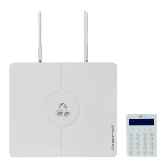
- Page 1 USER MANUAL PT-1090...
- Page 3 Wiring Diagram Pickup SIM Card interface Speaker interface Batt WPS/ POWER LAN1 LAN2 LAN3 LAN4 RESET L E D F L A S H BELL. 0 PBUS . A0RLY0B + 12V - A-ZONE-B A-KEY-B + 12V - Z1 COM Z2 Z3 COM Z4 + 12V - Z5 COM Z6 Z7 COM Z8 TAMPER 2.2K...
- Page 4 Wired Siren Wiring Instructions Ê ÛØáê Ü åÜ á Úê Ü çÛê Ü åØ×æÜ åØá Ÿ ã ß ØÔæ ØåØÙ Øåçâç ÛØÙ â ß ß â ê Ü á ÚÖâ á á ØÖçÜ â áà ØçÛâ × - Fà ÒS5·˜Ï J Siren ¾...
- Page 5 Z 08 Expansion Module Description Wiring instructions DIP switch Power Indicator Zone status indicator +12V GND B1 Z1 ) 53 ) 53 ) 53 ) 53 +-4* Light Power indicator: always on when power is on; Zone status indicator: Zone is enabled and flashes slowly when normal When the zone is faulty, it always lights up.
-
Page 7: Table Of Contents
Content Foreword Features Led instruction of network alarm platform Insert SIM card Panel led instruction Insert SIM card Remote phone control Take alarm call from alarm panel GSM SMS remote control FC-7602 Dual Zone Expansion Module keypad instructions Wiring instructions Keyboard address setting Function button Led lights... - Page 8 3.1.2 Set CMS line 2 3.1.3 Set account 3.1.4 Enter dial times 3.2 Network CMS 3.2.1 Set server IP 3.2.2 Set server port 3.2.3 Set CMS account 3.3 SIA platform 4. Set voice phone 4.1 Voice phone 4.2 Phone dial times 5.
- Page 9 7.1 Set zone type 7.2 Set zone siren 7.3 Doorbell tone set 7.4 Keyboard zone 8. Set system area 8.1 Password area 8.2 Keypad area 8.3 Remote area 8.4 Zone area 8.5 Voice phone area 8.6 Slect partition 9.S et other 9.1 Wired zone 9.2 Relay 9.3 SIM card set...
- Page 10 2.7.2 Bypass group setting 2.7.3 Relay settings 2.7.4 Keyboard area settings 2.7.5 Keyboard fault display 2.8 System log 3. Network settings 3.1 TCP/IP settings 3.2 GPRS settings 3.3 Email settings 3.4 CMS platform 3.5 SIA platform 3.6 PSTN alarm platform settings 4.
-
Page 11: Foreword
Congratulations on your obtaining a set of reliable and multi-functional security products that have been tempered and passed a variety of certifications. PT-1090 is an intelligent anti-theft alarm control panel that integrates anti-theft, fire prevention and gas leakage prevention, and is compatible with wired and wireless alarm methods. -
Page 12: Features
User manual Features § Can be divided into 4 independent areas, with 32 wireless zones, 8 wired zones, 56 expansion zones can be expanded by bus port (including 24 keyboard expansion zones and 32 bus zones), 32 single-bus zones, total support 128 zones. -
Page 13: Panel Led Instruction
User manual Panel led instruction Arm and disarm status LED: Area 1, LED is always ON when armed, LED is OFF when disarmed, flash once every second when stay armed Alarm LED:Area 1, flashes when alarming, LED always ON when zone fault, LED flashes once per second when AC or battery fault Network LED: LED is always ON when the network is normal, LED is OFF when the network is fault, and LED falshes quickly when the network is... -
Page 14: Remote Phone Control
User manual Remote phone control DK~DK~ You will hear: Enter password The alarm panel take the phone call User call the phone # after finish 7 times ringing(factory of the alarm panel default is 7 times) Press 1 to arm area Press 2 to disarm area Press 3 to stay area Press 4 to check area status... -
Page 15: Gsm Sms Remote Control
Note: X is the area #, from 1 to 4. Default use password 1234(no space). You will receive a reply sms message if the panel accept and proceed your SMS command. FC-7602 Dual Zone Expansion Module The starting zone number of the mainframe extended zone is 41. PT-1090 DIP code example: Area 1:81 { 41+(32+8)→... - Page 16 User manual white wire (RS487B), green wire (NC1), black wire (GND), blue wire (NC2). 4. Operating voltage range: DC8.5~24V. 5. The 1st bit of the DIP switch is the tamper detection switch, ON turns on the tamper detection, OFF means the tamper detection off; 2~8 are the address bits, ON is valid, OFF is invalid, the address calculation method is binary, For example, the address of defense zone 1 is 81: the dial code of positions 3 and 5 needs to be dialed to the ON position, and the address of zone 2 is 82.
-
Page 17: Keypad Instructions
User manual Keypad instructions Terminals Touch keys DIP switch ) U RQWY L HZ 5HDUYL HZ Wiring instructions Please follow the wiring diagram below to connect. ˜›–Š••¢1Œ•˜œŽ• ˜›–Š••¢1˜™Ž—Ž• Host KEY-B KEY-B Host N1 C1 N1 C1 connection N1 O1 connection KEY-A KEY-A port... -
Page 18: Function Button
User manual Function button Icon Meaning Instructions The button can set arm multiple partitions at one time, and can also arm individual partitions separately.Press and hold for 3 seconds for emergency alarm The button can set multiple partitions to stay status, and can Stay also set stay on a single partition.Press and hold for 3 seconds for medical care... -
Page 19: Common Operation
User manual Support 8 keypad. Pls scan and add keypad after repower the alarm panel. The keypad will not work if add without repower the alarm panel, in this case, you can re-scan to add the keypad on a keypad which already work by the command admin PW[012345]*9#. - Page 20 User manual ,or press One- key arm: Press Area No.+ Instant Arm: , or user password+ + Area No. Event logs: Press in the standby mode to view the event log, Up to 800 event records can be stored cyclically. Enter the bypass zone:...
-
Page 21: Public Zone
User manual Public zone When a zone belongs to multiple areas, this kind of zone is called a public zone, which is mainly used in shared passages and other places. The public zone will only alarm when the zone where it is located has alarm conditions, and when it is a delayed zone , If any area it belongs to cancels the alarm, the other areas it belongs to will also cancel the alarm;... -
Page 22: Duress Password
User manual Duress password When you enter the duress password,you will trigger an duress alarm.If enter duress password When the system is under arm status,keypad will display system is disarmed,stop siren but send alarm info and alarm call. (pls set the CMS phone # and follow me phone #) Example,A arm the system,B enter the area and trigger alarm,B threaten A disarm the system. -
Page 23: Arm/Disarm Alarm Panel
User manual Arm/disarm alarm panel Disarm ½ ½ ~ ~ ~ ~ AREA [ AREA DISARM Corresponding user password + Corresponding user password + or by pressing the disarm button of the or press disarm button remote control. corresponding remote control. Panic alarm Stay ½... -
Page 24: Alarm Procedure
User manual Alarm procedure Tele Telephone Telephone Call phone 3. when the alarm panel starts the alarm, it will dial the area phone # by preset call times. If the number of alarms is multiple, it will start cycle alarming by the second and third steps. -
Page 25: System Maintenance
User manual System maintance Pls make the below test before installation. Communication test: main user password+*1#; battery test: main user password+*2#. Siren test: main user password+*3# Walk test: main user password+*4#(disarm all area before start walk test) 1)C ommunication test: test the communication between alarm panel and CMS. CMS will receive timing test +[1]+ Main user password+... -
Page 26: Programmable Output
User manual 5) Wireless switch management The wireless switch can realize the alarm linkage output with the corresponding defense zone, and 32 wireless switches can be set. Enter wireless switch +[5]+ Main user password+ & management Programmable output According to the set state parameters, when a specified event or state occurs, the programming output port voltage changes from 0V to 12V. -
Page 27: System Setting
User manual I. System setting 1.SET SYS PASSWORD 2.SET SYS NETWORK 3.SET CMS 4.SET VOICE PHONE 5.SET SYS OPTIONS [012345] + +[0]+ 6.SET WIRELESS 7.SET SYSTEM ZONE 8.SET SYSTEM AREA 9.SET OTHERS 10.ADVANCED SET Note: only in disarm status, user can do system setting. 1.Set sys password 1.ADMIN PWD [012345] +... -
Page 28: Set Main User Code
User manual ENTER PASSWORD: [012345] + +[0]+ & & & ****** + [555555] + & LCD display Press 6 times to delete the old password The keypad will beep twice to confirm the password has been changed. Back to standby interface. &... -
Page 29: Set Ip
User manual DHCP: + [2]+ [012345] + +[0]+ & & 1>DISABLE 2>ENABLE & LCD display + [2] + & The keypad will beep twice to confirm it has been changed,the keypad will return to previous setting Press back to standby interface. &... -
Page 30: Set Subnet Mask
User manual 2.4 Set subnet mask E.g. Set subnet mask as 255.255.255.0 ENTER SUBNET MASK: + [2]+ +[4]+ [012345] + +[0]+ & & LCD display + [255255255000] + & The keypad will beep twice to confirm it has been changed, the keypad will return to previous setting.Press back to standby interface. -
Page 31: Set Cms Line
册 User manual 手 品 产 3.1.1 Set CMS line 1 When alarm is triggered, the central panel will dial CMS telephone No to inform the central monitor server. It can support to set 18 digits maximum. E.g. Set Set CMS line as 800012345 + [3]+ [012345] + +[0]+... -
Page 32: Network Cms
User manual 3.2 CMS platform + [3]+ +[2]+ [012345] + +[0]+ & & & 1>SET SERVER IP 2>SET SERVER PORT 3>SET CMS ACCOUNT 4>SET CMS PASSWORD 3.2.1 Set server IP Set CMS IP as 014.152.090.065 + [3]+ +[2]+ [012345] + +[0]+ &... -
Page 33: Sia Platform
User manual + [3]+ +[2]+ +[3]+ [012345] + +[0]+ & & & & LCD will show the CMS register ID and password. Press back to standby interface. & The query CMS password is the same as the registration ID. 3.3 SIA platform For the setting of SIA platform, please refer to the setting method of CMS . -
Page 34: Set Sys Options
User manual + [4] + [012345] + +[0]+ + [5]+ & & & PHONE DIAL TIMES: 5 + [06] + & (01-15) LCD display The keypad will beep twice to confirm it has been set, the keypad will return to previous setting.Press back to standby interface. -
Page 35: Entry Delay
User manual 5.2 Enter delay When alarm happens from delay zone, the device will delay to alarm for 15s in factory default.E.g. Set enter delay time as 20s. [012345] + +[0]+ + [5] + + [2] + & & & ENTER DELAY 1: 15 + [020] + &... -
Page 36: Force Arm
User manual 5.5 Force arm Factory default: enable When there is zone fault, user will be not able to arm the device. But if set force arm, it is OK to arm, at the same time, the zone in fault will be bypassed with SMS or CMS report. -
Page 37: Door Sensor Check
User manual 5.8 Door sensor check When the door sensor is open, the panel will display zone trouble(default value is disable), example: set door sensor check to be enable. [012345] + +[0]+ + [5] + + [8] + & & &... -
Page 38: Set Wireless
User manual 6. Set wireless 1]SET REMOTE 2]SET WLS DETECTOR [012345] + +[0]+ + [6] + & & 3]SET WLS SIREN 4]RF SWITCH 6.1 Set remote 1)ENROLL REMOTE [012345] + +[0]+ + [6] + 2 )ENTER REMOTE CODE & & &... -
Page 39: Delete Remote
User manual [012345] + +[0]+ + [6] + +[2]+ & & & & ENTER REMOTE:1 ENTER REMOTE CODE + [3] + & (1--8) LCD display LCD display ENTER REMOTE:4 + 226016063 . & (1--8) LCD display The keyboard beeps twice, indicating success. After the addition is completed, the keyboard will automatically enter the next remote adding. -
Page 40: Enroll Detector
User manual 6.2.1 Enroll detector Example: enroll detector to #2 detector in the alarm panel. [012345] + +[0]+ + [6] + + 2 . & & & & ENTER DETECTOR #: 1 TRIGGER WLS DEVICE + [02] + & (01--32) LCD display LCD display ENTER DETECTOR #:... -
Page 41: Delete Detector
User manual 6.2.3 Delete detector [012345] + +[0]+ + [6] + + 2 . +[3]+ & & & & ENTER DETECTOR #: 1 DELETE DEVICE? + [03] + & (01--32)00 DEL ALL LCD display LCD display ENTER DETECTOR #: 4 &... -
Page 42: Delete Siren
User manual [012345] + +[0]+ + [6] + + 3 . & & & & SIREN IN PROGRAM, ENTER SIREN #: + [2] + & (1--4) TO START CODING LCD display LCD display CODING & LCD display Press save button in the siren 1 WAY SIREN CODING &... -
Page 43: Enroll Switch
User manual 6.4.1 Enroll switch Example: auto the wireless switch to the # 2 switch in alarm panel. [012345] + +[0]+ + [6] + + 4 . & & & & ENTER SWITCH#: 1 TRIGGER WLS DEVICE + [02] + &... -
Page 44: Set System Zone
User manual [012345] + +[0]+ + [6] + + 4 . + 3 . & & & & ENTER SWITCH#: 1 DELETE DEVICE + [03] + & (01--32)00 DEL ALL LCD display LCD display ENTER SWITCH#: 4 & (01--32)00 DEL ALL LCD display The keyboard beeps twice, indicating success. -
Page 45: Set Zone Type
User manual When the common zones set off alarm. All users in related area will receive notification. but there is an exception. When one area is with arm deleay setting. The other areas are armed, but the area which with arm delay time not finish yet. During this period, common zone triggered. -
Page 46: Set Zone Siren
User manual Example: Set Zone 8 to be fire zone. ENTER ZONE: [012345] + +[0]+ + [7] + & & & (001--128) LCD display SELECT ZONE TYPE:0 ENTER ZONE: + [008] + + [7] + & & 0>DISABLE (001--128) LCD display LCD display The keyboard beeps twice, indicating success. -
Page 47: Keyboard Zone
User manual [012345] + +[0]+ + [7] + + [3] + & & & ENTER ZONE #: 01 DOORBELL TONE SET: + [012] + + [2] + & 1>DISABLE 2>ENABLE (001--128) LCD display LCD display ENTER ZONE #: 13 & (001--128) LCD display The keyboard beeps twice, indicating success. -
Page 48: Set System Area
User manual 8. Set system area 1]PASSWORD AREA 2]KEYPAD AREA [012345] + +[0]+ + [8] + 3]REMTOE AREA & & 4]ZONE AREA 5]VOICE PHONE AREA 6]SLECT PARTITION Total 4 areas, the zones can be assigned to one or more areas. If the zones are assigned to more areas, the zones are common zones. -
Page 49: Keypad Area
User manual 8.2 Keypad area (default value is area 1) The keypad only display the assigned area information. Example: set keypad 1 to mange area 2 [012345] + +[0]+ + [8] + + 2 . & & & #:1 ENTER KEYPAD AREA:... -
Page 50: Voice Phone Area
User manual [012345] + +[0]+ + [8] + +[4 . & & & AREA: 1234( * SEL) ENTER ZONE: 01 +[055]+ & (001--128) MANAGE: LCD display LCD display ENTER ZONE: 56 & (001--128) LCD display The keyboard beeps twice, indicating success. After the setting is completed, the keyboard will automatically enter the next setting. -
Page 51: S Et Other
User manual [012345] + +[0]+ + [8] + +[6 . & & & AREA: 1234( * SEL) ENTER SERIAL NO.:1 & (1--4) MANAGE: LCD display LCD display ENTER SERIAL NO.:3 & (1--4) LCD display The keyboard beeps twice, indicating success. After the setting is completed, the keyboard will automatically enter the next setting. -
Page 52: Relay
User manual [012345] + +[0]+ + [9] + & & & ENTER ZONE NO.: 1 WIRED LOOP TYPE:1 + 03 & (01--08) 1>EOL 2>N.O. 3>N.C. LCD display LCD display ENTER ZONE NO.: 4 & (01--08) LCD display The keyboard beeps twice, indicating success. After the setting is completed, the keyboard will automatically enter the next setting. -
Page 53: Sim Default Set
User manual 9.3.1 SIM card priority setting The SIM card to be used first when enabling the SIM card network, making calls, sending text messages and other functions. The default is SIM card 1 priority. Example: set SIM card 2 priority. [012345] + +[0]+ + [9] +... -
Page 54: Timing Arm/Disarm
User manual 9.4 Timing arm/disarm 1>TIMING ARM/DIS.1 2>TIMING ARM/DIS.2 [012345] + +[0]+ + [9] + + [4] + & & & 3>TIMING ARM/DIS.3 4>TIMING ARM/DIS.4 Automatically carry out arming / disarming operations at a certain time set. You can set 4 groups of timing arm/ disarm operations can be set, and the default is off. -
Page 55: Device Status
User manual 9. 5. 1 Device status: After entering the device number, click "#" to query the device status. Device information query: [012345] + +[0]+ + [9] + + [5] + & & & & ENTER SERIAL NO.: 1 TYPE:INFRA.DUALTECH &... -
Page 56: Device Restart
User manual [012345] + +[0]+ + [9] + + [5] + + [3] + & & & & ENTER SERIAL NO.:01 (01-32) LCD display Enter the serial number of the device and press # to enter the setting. The keyboard beeps twice, indicating that the setting is complete.Enter a setting item. Press back to standby interface. -
Page 57: Keypad Fault Disp
User manual [012345] + +[0]+ + [9] + + [5] + + [5] + & & & & ENTER SERIAL NO.: 1 DEVICE :02 RESTORE? + [22] + & (01-32) LCD display LCD display ENTER SERIAL NO.: 3 & (01-32) LCD display The keyboard beeps twice, indicating that the factory settings are restored successfully. -
Page 58: Advanced Set
User manual 10.Advanced set. Without voice prompt,programme address and the corresponding options as below: 001--System Language 916--Alarm_cancel 002-- Ring Times 0~15 917--Detector_low_bat 003--Communication Test Time 918--Detector_bat_ok 0~999S 919--Wireless_loss 005--Wireless Detector Tamper 920--System_programme 006--Arm/Disarm Siren Short Sound Tone 921--Arm_fail 922--Comm_test 923--Event_bypass 007--Web Port 0~65535 924--Sys_bat_recovery... - Page 59 User manual 001—System Language: 1. Chinese 2. English 002—Ring Times(the default setting is 3 times): set value 0 15.0 means not answering the call. 003—Communication Test Time: set value 0 999s.0 means no test. 005—Wireless Detector Tamper: 1. Disable 2. Enable 006—Arm/Disarm Siren Short Sound Tone: 1.
-
Page 60: Web Ie Setting
User manual II.Web IE introduction Enter the System setting of host, set the IP address and gateway in the network settings. 1. Access to the host Users can use the web administrator account, primary user account and general user account to log in the web page. Different account types have different permissions. Web administrator account has the highest permissions, while primary user account has partial permissions.General user account can only set permissions for arm and disarm. -
Page 61: Basic Management
User manual 2. Basic management 2.1 System Kanban System Kanban can view real-time data of Device Status, Network and Internet, System Arm/Disarm, Smart Device, Latest Alert, etc. Data Kanban: Display the real-time data of Today’s alarm,Yesterday's alarm , Wired zone, and Wireless device. Device Status: the connection status of AC , Platform, Back battery, etc. -
Page 62: System Management
User manual 2.2 System management The added zones can be set here: 1-8 are wired zones, 9-40 are wireless zones, ● 41-96 are extended zones, 97-128 are single-bus zones. Red“ ”means fault, and ● green “ ”means the fault is already cleared. Bypass: Refers to temporarily failing the zone when Arm, so that it can cancel the alert state.After the zone is disarmed, the zone will be restored to the normal zone. -
Page 63: Wireless Device
User manual 2.3 Wireless device Auto search: Click “Auto search” to trigger the wireless device to automatically check the code. Note that the trigger of the wireless device must be within 30 meters from the host; Add manually: Manually enter the 9-digit address code of the wireless device to add.As shown in the figure, the device type includes Remote, Detector, Electrical switch, and Siren.Set the Device number and Device name when adding, and check the area and enter the 9-digit wireless address code at the bottom of the device.For... -
Page 64: Single Bus Device
User manual 2.4 Single bus device Please refer to the manual to set the connected single-bus device.Restart and Restore to factory settings need to enter the administrator password (The default is 012345). 2.5 Smart control Smart control means remote control and setting of wireless switch name and timing automatic switch.The device name can be modified in "Wireless Device".Other setting items can be directly clicked to modify or check, multiple loops can be timed, and the operation of the device is the operation (open or closed) - Page 65 User manual Mode 2: There is a sequence. Only when Zone 2 is triggered first, then Zone 1 is triggered within the setting time range, the alarm will be triggered.and it will not alarm if Zone 1 is triggered first , then zone 2 is triggered; Mode 3: There are sequence and direction.
-
Page 66: Other Settings
User manual Electrical switch linkage/ PGM linkage: Triggering the setting alert within the effective time will execute the action of turning on or off of the electrical switch/PGM. 2.7 Other settings 2.7.1 Wired zone settings Wired zone loop type: EOL, N O N C And the default is EOL. EOL When the resistance at the end of the line in the zone is 2 2K it is normal and the zone will alarm if it is open circuit or short circuit;... -
Page 67: Bypass Group Setting
User manual 2.7.2 Bypass group setting A bypass group can select up to 16 defense zones, and up to 8 bypass groups can © be set. Click the drop-down window " to select. 2.7.3 Relay settings Relay circuit type: N mode can be selected, and the default mode is 2.7.4 Keyboard area settings Assign the keyboard to one or more areas... -
Page 68: Keyboard Fault Display
User manual 2.7.5 Keyboard fault display When the network cable or phone card is not inserted or not inserted properly, the keyboard display screen shows the Network fault, and the fault can be removed by inserting the network cable or phone card properly And you can also disable this fault in this setting and the keyboard display will not display the fault All display is turned on by default and the user must click Save after completing the settings 2.8 System log... -
Page 69: Network Settings
User manual area code: 141-148; main user keyboard defense area code: 170; common user keyboard defense area code: 171-202. Defense zone code composition: 1-8 are wired defense areas, 9-40 are wireless defense areas, 41-96 are extended defense areas, 97-128 are single-bus defense areas, 129-136 are keyboard defense areas (keyboard emergency alarm or disassembly alarm), 137 -140 is the wireless siren defense zone (demolition alarm). -
Page 70: Gprs Settings
User manual 3.2 GPRS settings This setting is for the host to use GPRS to access the network, and the default SIM card network will be used first. When the default SIM card fails, the backup SIM card network will be enabled. SIM card 1 is limited to 2G network, and SIM card 2 supports 4G network.This device does not support 5G currently. -
Page 71: Email Settings
User manual 3.3 Email settings a. SMTP server: fill in the SMTP server address that you want to send mail correctly, if you use 163 mailbox, the SMTP server address is: smtp.163.com b. SMTP port: The default is 25 (SSL encryption port is not supported temporarily) c. -
Page 72: Sia Platform
User manual Alarm platform server and port: Fill in according to the server. Heartbeat time: Refers to the time interval for the device to send a heartbeat message to the platform the last time it was sent.At every heartbeat interval, the device will send heartbeat information to the platform.After receiving the heartbeat information, the platform will record the time of receiving the heartbeat. - Page 73 User manual is abnormal, the host will start GSM to send data. After the setting is completed, click w[Save Settingsw\ to take effect after restarting. Server 1 Server 2 Server 1 Server 2 PANEL PANEL Single-platform Mode Dual-platform Mode...
-
Page 74: Pstn Alarm Platform Settings
User manual 3.6 PSTN alarm platform settings Ademco Contact ID protocol When setting the alarm call enterw[ Pw\ in the phone number and the dialing will pause for 1 second The number of dialing is 5 times by default When the alarm is triggered the host will make a call to the alarm receiving platform When the phone number 1 is not connected the host will automatically dial the phone number 2 and make a circular call within the number of dialing set by the user... - Page 75 User manual 4> Detector loss detection time within this time period the host inspects if receive any status report or alarm from the detector. If not, the host will show this detector lost 5> AC power detection time After AC power failure it is the time that the host delay to upload report information to the alarm center(default is 30 minutes).
-
Page 76: Alert Settings
User manual can not be armed when zones are in trouble factory default disable 12> Quick arm: if enable user can arm the system via keypad without entering password If disable user need to enter password to arm via keypad Click save after setting 13 Local voice prompt: arm disarm alarm voice prompt and so on in host factory default enable... -
Page 77: Password Settings
User manual host will give priority to PSTN to send data The host can choose whether to send the data to the user or platform and how to send it to the user When the network fails GPRS will be enabled to connect to the platform;... -
Page 78: 4 Voice Call Settings
Primary user: it is used to login web page,password is 1234 by default. User can modify some settings in web IE interface 4 4 Voice call settings Four voice phones can be set, and one phone number can control 1-4 partitions. When an alarm occurs in the selected partition, the host will send information to the phone number of the partition. -
Page 79: Timing Arm/Disarm
User manual check "Call Voice Call" and "Send SMS" for the phone/message function to take effect. Redial times: the number of voice calls in case of alarm. When the phone number 1 is not answered, the phone number 2 will be dialed. The default is redial 5 times. -
Page 80: System Maintenance
User manual 5.System maintenance 5.1 System information Display the host web page, voice, hardware and firmware version number. Users can also use the mobile app to scan the QR code to add a host, see Chapter 5 about mobile app usage for details. 5.2 Time settings Set time automatically: when it is turned on, it will automatically check the time with the timing server;... -
Page 81: System Restart
User manual You can modify the time manually at the current time. If "synchronize with computer time" is enabled, the manual setting is invalid. After setting, click "Save Settings". 5.3 System restart Click the w[Restart noww[ button, then pop up “Do you really want to restart?”... -
Page 82: System Backup
User manual 5.4 System backup If you want to set the parameters of multiple hosts to the same configuration, you can export the set device parameters, and then import the exported files to other hosts to be set. Click "backup configuration file", the bottom of the screen prompts that the "bin"... -
Page 83: System Upgrade
User manual 5.6 System upgrade The web program file is “ Web.bin ”, the voice program file is“ Audio.bin ”, the firmware program file is “ FC7664Pro.hex ”File, in the process of upgrading, there will be a green bar and percentage process display at the bottom of the page, please do not turn off the page and turn off the power in the process of upgrading. -
Page 84: App Use
User manual III. App use 1. Download and installation Please scan QR code below to download IOS&Android app, or search “smartsecruity” in IOS&Googleplay store. Android iPhone 2. Account registration For new users/ please click % user registration”. Click the app to enter login interface as show in the right. User name: (EMAIL) Password: (set as you like) After setting, click “Register”. -
Page 85: Add Panel
User manual 3. Add panel The first login will first enter the add interface, click "+" to add the QR code at web, or click "+" in the regional interface to enter the scanning interface. Click "OK" to add the device to the app. Initial login screen 4. -
Page 86: Add Other Accessories
User manual Click Online Device-Settings- Zone Settings,TFM FDUU I F[ POFUPC FC PVOE DM JDL CJOEE FW JDF T FM FDUU I FDBN FS BBOETBW FJU 5. Add other accessories Click Online Device-Settings, select the type of device to be added for operation. Example of adding remote control: a. -
Page 87: Technical Specifications
User manual Technical specifications External AC power supply voltage: input 110 ~ 240VAC, output 15V DC / 3A Host built-in rechargeable battery (optional): 12V / 7Ah Low battery voltage: ≤11V Backup battery duration: about 24 hours (when only one keyboard is connected) Alarm dialing mode: internet alarm, telephone alarm and GSM alarm DTMF dial frequency deviation: <... -
Page 88: Product Function Limitation
User manual Product function limitation Although the alarm device you purchased is highly safe, it is still not 100 safe. No matter how advanced the alarm system is, there will be false alarm or failure. The reasons may be as follows: Lack of maintenance: if the system is used for a long time, but maintenance and testing are not carried out immediately, the sensitivity of the detector may be reduced and false alarm or missing alarm may occur;...
Need help?
Do you have a question about the PT-1090 and is the answer not in the manual?
Questions and answers