Table of Contents
Advertisement
Quick Links
Contents
User's Manual
The content in this manual has been carefully prepared and is believed to be accurate, but no
responsibility is assumed for inaccuracies.
For
Soprolec reserves the right to make changes without further notice to any products herein to
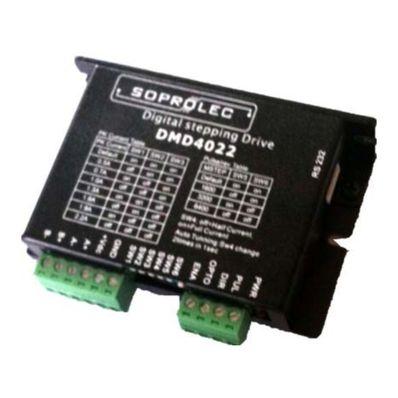
DMD4022
improve reliability, function or design. Soprolec does not assume any liability arising out of the
application or use of any product or circuit described herein; neither does it convey any license
under its patent rights of others.
Fully Digital Stepping Driver
Soprolec's general policy does not recommend the use of its products in life support or aircraft
Version 1.0
applications wherein a failure or malfunction of the product may directly threaten life or injury.
©2009 All Rights Reserved
According to Soprolec's terms and conditions of sales, the user of Soprolec's products in life
Attention: Please read this manual carefully before using the driver!
support or aircraft applications assumes all risks of such use and indemnifies Soprolec against all
damages.
18 bis, rue du vert buisson
©2009 by Soprolec
95470 VEMARS
All Rights Reserved
France
Phone : +33 (0)6 3104 3562
Fax : +33 (0)1 3431 3917
Internet :
www.soprolec.com
E-Mail :
contact@soprolec.com
II
Advertisement
Table of Contents

Related Manuals for SOPROLEC DMD4022

Summary of Contents for SOPROLEC DMD4022
- Page 1 Fully Digital Stepping Driver Soprolec’s general policy does not recommend the use of its products in life support or aircraft Version 1.0 applications wherein a failure or malfunction of the product may directly threaten life or injury.
-
Page 2: Table Of Contents
Contents Contents Dynamic current setting ................10 Table of Contents Standstill current setting ................10 1. Introduction, Features and Applications..............1 8. Wiring Notes......................10 Introduction ......................1 9. Typical Connection....................11 Features ......................... 1 10. Sequence Chart of Control Signals................ 11 Applications...................... -
Page 3: Introduction, Features And Applications
1. Introduction, Features and Applications Introduction Electrical Specifications (T = 25℃/77℉) The DMD4022 is a versatility fully digital stepping driver based on a DSP with advanced control DMD4022 algorithm. The DMD4022 is the next generation of digital stepping motor controls. It brings a Parameters... -
Page 4: Operating Environment And Other Specifications
Natural Cooling or Forced cooling Selecting Active Pulse Edge and Control Signal Mode Avoid dust, oil fog and corrosive gases Environment The DMD4022 supports PUL/DIR and CW/CCW modes and pulse active at rising or falling edge. 0 -50 (32℉-122℉) Ambient Temperature Operating See more information about these settings in Section 13. -
Page 5: Connecting The Motor
5. Connecting the Motor motors should be run at only 70% of their rated current to prevent over heating. The DMD4022 can drive any 2-pahse and 4-pahse hybrid stepping motors. Connections to 4-lead Motors 4 lead motors are the least flexible but easiest to wire. Speed and torque will depend on winding Figure 6: 6-lead motor full coil (higher torque) connections inductance. -
Page 6: Connections To 8-Lead Motors
+20 ~ +36VDC, leaving room for power The DMD4022 can match medium and small size stepping motors (from NEMA frame size 14 to fluctuation and back-EMF. -
Page 7: Selecting Microstep Resolution And Driver Output Current
Theoretically, this will reduce motor heating to 36% (due to P=I *R) of the original value. If 6400 the application needs a different standstill current, please contact Soprolec. Current Settings 8. Wiring Notes For a given motor, higher driver current will make the motor to output more torque, but at the In order to improve anti-interference performance of the driver, it is recommended to use twisted pair shield cable. -
Page 8: Typical Connection
Low level width not less than 7.5µs. 11. Protection Functions To improve reliability, the driver incorporates some built-in protection functions. The DMD4022 uses one RED LED to indicate what protection has been activated. The periodic time of RED is 3 Figure 9: Typical connection s (seconds), and how many times the RED turns on indicates what protection has been activated. -
Page 9: Phase Error Protection
turn on twice within each periodic time (3 s). Phase Error Protection Motor power lines wrong & not connected will activate this protection. RED LED will turn on four times within each periodic time (3 s). When above protections are active, the motor shaft will be free or the LED will turn Attention: red. -
Page 10: Professional Tuning Software Protuner
13. Professional Tuning Software ProTuner Introduction This section will provide an overview of connection and basic setup instructions for Soprolec’s digital stepping driver DMD4022 using the ProTuner software. These instructions will walk you through the following steps necessary to start up your driver and motor. This section is intended for setting up the driver with the ProTuner. - Page 11 Figure 13: User’s information settings Figure 15: Shortcut folder setting Set the “Shortcut Folder” in Figure 15 and continue to install the ProTuner by following Figure 16 and Figure 17. An Installation Successful window will appear if the ProTuner is installed successfully.
-
Page 12: Connections And Testing
Testing the Stepping System Figure 17: Installing the ProTuner Turn on the power supply, the green (Power) LED will light. The DMD4022 has default parameters stored in the driver. If the system has no hardware and wirings problem, the motor should be locked and the driver should be ready. -
Page 13: Com Config Window
Com Config Window Figure 21: RS232 communication configuration window Figure 22: Current Tuning window Serial Port: Select the serial communication port to which the driver is connected. The factory default setting is COM1. Ki: Integral Gain. Integral Gain helps the driver to overcome static current errors. A low or zero value for the Integral Gain may have current errors at rest. -
Page 14: Anti-Resonance Introduction
This feature requires that the driver be configured with respect to the total inertia in the then Motor self-test and parameter auto-setup technology of the DMD4022 can replace manual tuning the driver with ProTuner. Just changes SW4 two times in 1 second, and then the driver will system. -
Page 15: Procedure For Achieving Optimum Performance
resonance area. Usually between 1.2rps and 2.4rps. better smoothing value by slightly moving the slider bars of AMP(s) and Phase(s) back and forth. ResonanceArea: Parameters for 2 Default Amp2 and Phase2 values are zero. It is very important to make the AMP(s) and Phase(s) adjustments at the proper test speeds with an unloaded motor. - Page 16 OverCurrent: Over-current Protection. Protection will be activated when continuous current exceeds 16A. OverVoltage: Over-voltage Protection. When power supply voltage exceeds 42 ± 1 VDC, protection will be activated. PhaseErr: Phase Error Protection. Motor power lines wrong & not connected will activate this protection.
-
Page 17: Appendix
SOPROLEC. warrants its products against defects in materials and workmanship for a period of 12 months from shipment out of factory. During the warranty period, Soprolec will either, at its option, repair or replace products which proved to be defective.
Need help?
Do you have a question about the DMD4022 and is the answer not in the manual?
Questions and answers