Table of Contents
Advertisement
Quick Links
Commercial Condensing Water Heater
INSTALLATION, OPERATION, AND
MAINTENANCE MANUAL
399-1000 MBH Water Heater Indoor/Outdoor
Water Heater Models
Model:
Installation Date:
Heating Contractor:
Address:
Thermal Solutions Products, LLC
Phone: 717-239-7642
AMPW 400
AMPW 500
AMPW 650
AMPW 800
AMPW 1000L
1175 Manheim Pike, Lancaster, PA 17601
WARNING
WARNING: If the information in these instructions
is not followed exactly, a fire or explosion may
result causing property damage, personal injury
or death.
DANGER
Do not store or use gasoline or other flammable
vapors and liquids in the vicinity of this or any
other appliance.
WHAT TO DO IF YOU SMELL GAS
• Do not try to light any appliance.
• Do not touch any electrical switch; do not
use any phone in your building.
• Immediately call your gas supplier from a
neighbor's phone. Follow the gas supplier's
instructions.
• If you cannot reach your gas supplier, call
the fire department.
Installation and service must be performed by
a qualified installer, service agency or the gas
supplier.
Serial Number:
System Type:
Phone/Email:
PN: 110820-01
Save this manual for future reference.
WARNING
DANGER
www.thermalsolutions.com
orders@thermalsolutions.com
Rev. 5, 4/23
Advertisement
Table of Contents

Related Manuals for Thermal Solutions AMPW 400


Summary of Contents for Thermal Solutions AMPW 400
- Page 1 Installation and service must be performed by AMPW 800 a qualified installer, service agency or the gas AMPW 1000L supplier. Model: Serial Number: Installation Date: System Type: Heating Contractor: Phone/Email: Address: Thermal Solutions Products, LLC www.thermalsolutions.com Phone: 717-239-7642 1175 Manheim Pike, Lancaster, PA 17601 orders@thermalsolutions.com...
-
Page 2: Table Of Contents
Venting Design Requirements Field Installation Room Air for Combustion PVC Venting Venting for Outdoor Installation General Termination Vent and Combustion Air Terminations Multiple Appliance Terminations Terminal Installation Polypropylene Venting Optional Room Air for Combustion Removing Existing Appliance Special Installation Requirements for Massachusetts Condensate trap VIII. Condensate Disposal Condensate Neutralizer Installation AMPW 400-1000L I&O Manual... - Page 3 Testing of Controls and Safety Devices General Maintenance XIV. Service and Maintenance Monthly Inspection Annual Inspections and Service Restarting after Prolong Shutdown Troubleshooting APPENDIX A: Tables APPENDIX B: Figures APPENDIX C: Default Light-off and Modulation Rates APPENDIX D: Gas Valve and Pressure Switch Tubing Schematics AMPW 400-1000L I&O Manual...
-
Page 4: Hazard Definitions
Failure to prevent the gas line from turning could damage correctly installed and are operating properly. the gas train components on the appliance (gas valve, 2. Factory warranty does not apply to units improperly blower, etc.). installed or improperly operated. AMPW 400-1000L I&O Manual... -
Page 5: Gas Leakage (If You Detect Or Smell Gas
Should overheating occur or the gas supply fail to shut California to cause cancer and birth defects or off, turn off the manual gas control valve to the appli- other reproductive harm. For more information ance. go to: www. P65Warnings.ca.gov. AMPW 400-1000L I&O Manual... -
Page 6: Product Rating, Specifications, And Dimensional Data
Appliance will go into hard lockout if temperature exceeds 200 Table 3: Appliance Connection Sizes AMPW Model Dimensions (in.) 1000L Gas Inlet Water Outlet Pipe (FNPT) Water Inlet Pipe (MNPT) Air Intake Vent Outlet Condensate Drain (PVC) Drain Line (FNPT) Electrical Conduit Holes AMPW 400-1000L I&O Manual... - Page 7 8 " 8 " 45" 2 " 2 " 8 " 4 " 2 " 4 " 4 " 8 " 8 " 8 " 4 " Front View Rear View 10" Figure 1: AMP 400-500 Dimensions AMPW 400-1000L I&O Manual...
- Page 8 8 " 4 " 45" 2 " 8 " 2 " 4 " 26 2 " 4 " 4 " 8 " 8 " 4 " 8 " Front View 10" Back View Figure 2: AMP 650-1000L Dimensions AMPW 400-1000L I&O Manual...
-
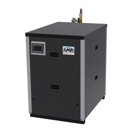
Page 9: Unpacking The Amp
Please read the instructions contained in this manual carefully as they provide important information Rear intake cover regarding the safe installation, use and servicing of this appliance. Figure 3: AMP 400-1000L with Outdoor Trim AMPW 400-1000L I&O Manual... -
Page 10: Amp Water Heater Component Identification
Connection to appliance gas train. See Table 29 for 4" female PVC slip provided for 400-500 models. model specific pipe sizes. 6" aluminum ring provided for 650-1000 models. 16. Inlet/Cold water connection 2" Male NPT inlet water connection to the appliance. AMPW 400-1000L I&O Manual... - Page 11 V. AMP Water Heater Component Identification (continued) Figure 4: Component Identification AMPW 400-1000L I&O Manual...
-
Page 12: Pre-Installation And Mounting
Ensure air intake accelerated component failure. pipe termination is away from areas that may Thermal Solutions DOES NOT warrant failures contaminate the combustion air (see Table 4). In caused by mis-sized appliance applications. DO particular, avoid areas near chemical products NOT oversize the appliance to the system. -
Page 13: Appliance Mounting
3 feet from its top. The area under the to prevent condensate from backing up inside the overhang must be open on 3 sides. heat exchanger. Never install directly on carpeted flooring. 4. Provide adequate space for condensate piping, condensate pump, or neutralizer kit. AMPW 400-1000L I&O Manual... -
Page 14: Amp 400-1000L Stacking
3. Stacking brace kit (PN: 111405-01) is included with AMP 400-1000L models. The kit includes 2 braces and 8 self drilling screws. Rotated Display (optionally field installed) Stacking Brace Self-Drilling Screws Figure 5: AMP 400-1000L Stacking Brackets and Display Rotation AMPW 400-1000L I&O Manual... -
Page 15: Clearances
Combustible CAUTION CAUTION Construction Do not install stacked pair of units 0" from another * Leave 24" clearance on at least one side. When installing under an overhang, conform to stacked pair. local codes. AMPW 400-1000L I&O Manual... -
Page 16: General Venting Guidelines
Common venting with other manufacturers' ap- to the rating of adjoining floor or ceiling. pliances or different Thermal Solutions models is 5. For flue gas venting, have horizontal runs sloping prohibited. -
Page 17: Field Installation
Combustion Air Total Vent Total Equivalent Length Equivalent Length Notes: 1. Total equivalent length cannot exceed maximum equivalent length shown in Table 6. 2. Combustion air and vent terminations do not count towards total equivalent length. AMPW 400-1000L I&O Manual... - Page 18 Note: Flow rates are based on the combustion of natural gas. Use of cellular core PVC (ASTM F891), cellular core CPVC, or Radel® (polyphe- WARNING WARNING nylsulfone) in non-metallic venting systems is prohibited. Covering non-metallic vent pipe and fittings with thermal insulation is prohibited. AMPW 400-1000L I&O Manual...
-
Page 19: Room Air For Combustion
The outdoor vent system requires field installed support. Do not rely on the vent adapter of the appliance to hold the vent material The outdoor vent kit may be shipped separately from the appliance. AMPW 400-1000L I&O Manual... -
Page 20: General Termination
1. It is recommended to use tees for both intake and vent terminations in extra windy locations. NOTICE NOTICE 2. All terminations shall have bird screens. 3. All non-metallic venting exposed to sunlight shall be UV resistant. AMPW 400-1000L I&O Manual... - Page 21 Covering non-metallic vent pipe and fittings with through a common conduit or chase so that thermal insulation is prohibited. one roof penetration may be made. Maintain recommended separations of terminations after penetration. Figure 8: Vent Terminal Clearances AMPW 400-1000L I&O Manual...
- Page 22 In accordance with the current CSA B149.1, Natural Gas and Propane Installation Code In accordance with the current ANSI Z223.1/NFPA 54, National Fuel Gas Code If locally adopted installation codes specify clearances different than those illustrated, then the most stringent clearance shall prevail. AMPW 400-1000L I&O Manual...
- Page 23 In accordance with the current CSA B149.1, Natural Gas and Propane Installation Code In accordance with the current ANSI Z223.1/NFPA 54, National Fuel Gas Code If locally adopted installation codes specify clearances different than those illustrated, then the most stringent clearance shall prevail. AMPW 400-1000L I&O Manual...
-
Page 24: Vent And Combustion Air Terminations
Do not use a barometric damper or draft hood culation. Recirculation of flue gas products into with this appliance. the combustion air supply can cause damage to property or the appliance. AMPW 400-1000L I&O Manual... - Page 25 Do not use Louvers for direct vent systems One appliance per gooseneck termination Vent and intake piping must not share the same gooseneck All terminations should have Bird/Rodent Screens Do not use rain caps, Rain will drain through boot tee or condensate drain AMPW 400-1000L I&O Manual...
- Page 26 To avoid/ minimize frost damage, extend the distance from building surfaces to vent termination end and increase the horizontal distance between adjacent vent terminations AMPW 400-1000L I&O Manual...
-
Page 27: Multiple Appliance Terminations
1/2 in. x 1/2 in. (13 mm x 13 mm) Alteration of the appliance vent connection is mesh. prohibited. 4. Adhere to the minimum and maximum wall thickness specified by the manufacturer of the wall penetration assembly. AMPW 400-1000L I&O Manual... - Page 28 4. For roof terminations, install vent terminal Above Snow Line downstream of prevailing winds relative to intake terminal. 5. It is recommended to use tee terminations with a vertical run in extra windy areas. Figure 12: Multiple Appliance Direct Vent Termination AMPW 400-1000L I&O Manual...
-
Page 29: Polypropylene Venting
Avoid combustion air contaminants in the boiler venting system. room. Permanently remove any contaminants found in the boiler room. If contaminants cannot be removed, do not use room air for combustion. AMPW 400-1000L I&O Manual... - Page 30 DO NOT use chimney for Combus- tion air intake. DO NOT insulate polypropylene vent pipes. Excessive heat could cause premature vent pipe failure. Figure 13: Flexible Vent in Masonry Chimney with Separate Combustion Air Intake AMPW 400-1000L I&O Manual...
- Page 31 This tions in this manual appliance operates at a positive vent pressure. Thermal Solutions takes no responsibility for vent v. A factory-built chimney used for venting an systems that create issues and or affect the per- appliance shall be certified.
-
Page 32: Removing Existing Appliance
Propane Installation Code, CAN/CSA B149.1. Resizing of any portion of the common venting system, should be done in accordance with the National Fuel Gas Code, ANSI Z223.1/NFPA 54 and/ or the Natural Gas and Propane Installation Code, CAN/CSA B149.1. AMPW 400-1000L I&O Manual... -
Page 33: Special Installation Requirements For Massachusetts
5. A copy of all installation instructions for all Product Approved sidewall horizontally vented gas fueled equipment, all venting instructions, all parts lists for venting instructions, and/or all venting design instructions shall remain with the appliance or equipment at the completion of the installation. AMPW 400-1000L I&O Manual... -
Page 34: Condensate Disposal
107860-08 107886-09 move the condensate to the drain. Select 107860-08 107886-09 a condensate pump approved for use with 107860-09 107886-10 condensing appliance—and equipped with an 107860-09 107886-10 overflow switch. 1000L 107860-06 107886-06 AMPW 400-1000L I&O Manual... -
Page 35: Water Piping
AMP water heater in a hot water supply system. The will cause corrosion of the steel components, and installer is responsible for complying with local codes. can lead to appliance failure. Thermal Solutions’ 1. The cold water return line shall be connected Standard Warranty does not cover problems to the inlet of the appliance labeled "cold water... -
Page 36: Factory Supplied Relief Valve Package
2" X 2" X 3/4" reducing tee the flow switch. 3/4" pipe nipple, close 3/4" X 1/2" reducing tee T&P relief valve 1/2" pipe nipple x 1-1/2" Long 1/2" full coupling T&P gauge Water flow switch AMPW 400-1000L I&O Manual... -
Page 37: Standard Piping Components
A factory installed 3/4” NPT drain valve and system debris from the hydronic system and connection is provided with the unit. protects the heat exchanger. Install the strainer in the primary piping going to the inlet of the appliance. AMPW 400-1000L I&O Manual... -
Page 38: Scalding
Failure to maintain the recom- Less than 5 seconds mended water hardness and flow rate will result in a buildup of scale inside the heat exchanger. Less than 3 seconds About 1-1/2 seconds About 1 second AMPW 400-1000L I&O Manual... -
Page 39: Water Quality
(Cl2) levels to be below 5ppm or size the circulator. and chloride (Cl ) levels to be below 150 ppm for 316 stainless steel. AMPW 400-1000L I&O Manual... -
Page 40: Temperature Rise And Heat Exchanger Head Loss
Required Flow = Output×1000/(500×ΔT), where flow rate is in GPM, output is in MBH, and ΔT is in 0F, Outputs are shown in Table 1. This water heater has a temperature rise (delta) limit of 55 °F AMPW 400-1000L I&O Manual... -
Page 41: Pump Selection
NOTE: The total loss includes 50 ft of pipe, 8 elbows, and 4 Valves. It is the installer's or system designer's responsibility to account for differ- NOTICE NOTICE ences in the circulation loop. Length, pipe diameter, elbows, and valves all contribute to the total pressure drop in the loop. AMPW 400-1000L I&O Manual... -
Page 42: Water Piping Diagrams
3. Some piping components cannot be supported by the piping. Refer to the man- CAUTION CAUTION ufacturers' installation instructions. 4. It is the installer's responsibility to select piping configurations that provide the proper flow rates and performance. AMPW 400-1000L I&O Manual... - Page 43 3. Some piping components cannot be supported by the piping. Refer to the man- CAUTION CAUTION ufacturers' installation instructions. 4. It is the installer's responsibility to select piping configurations that provide the proper flow rates and performance. 5. Erosion could occur if common piping is undersized. AMPW 400-1000L I&O Manual...
- Page 44 3. Some piping components cannot be supported by the piping. Refer to the man- CAUTION CAUTION ufacturers' installation instructions. 4. It is the installer's responsibility to select piping configurations that provide the proper flow rates and performance. 5. Erosion could occur if common piping is undersized. AMPW 400-1000L I&O Manual...
-
Page 45: Gas Piping
Locate the field supplied gas pressure regulator a 11. Gas piping shall be supported by fixed hangers or minimum of 10 ft from the appliance with no more stands and not by the appliance. than 1 elbow in-between. AMPW 400-1000L I&O Manual... - Page 46 0.824 22.9 11.4 ½ 1.049 29.1 14.6 ¾ 1.38 38.3 19.1 1.61 44.7 22.4 11.2 1¼ 2.067 57.4 28.7 14.4 11.5 10.3 1½ 2.469 68.5 34.3 17.1 13.7 12.3 3.068 85.2 42.6 21.3 17.1 15.3 2½ AMPW 400-1000L I&O Manual...
-
Page 47: Gas Pressure Switches
Low Gas Inlet Size (In. W.C.) (In. W.C.) Pressure Switch Pressure Switch (In.) Model (In. W.C.) (In. W.C.) Natural Propane Natural Propane Natural: 3 LP: 7 1000L Factory default high and low gas pressure switch setpoint. AMPW 400-1000L I&O Manual... -
Page 48: Electrical
1. 1. Route all field connections through conduits into Route all field connections through conduits into Verify Proper operation after servicing. the rear control box. the rear control box. AMPW 400-1000L I&O Manual... -
Page 49: System And Circulation Pump Wiring
AIR DAMPER 6.3A, SLOW BLOW (IF USING 5mm X 20mm FUSE ROOM AIR) * For indirect water heating with boiler models. Use Primary Pump for direct water heating with water heater models. Figure 21: 120 VAC Connections PCB AMPW 400-1000L I&O Manual... - Page 50 XII. Electrical (continued) Figure 22: Low Voltage Connections PCB AMPW 400-1000L I&O Manual...
- Page 51 COMBUSTION AIR DAMPER AND PROVING SWITCH ARE REQUIRED IF USING ROOM AIR FOR COMBUSTION WITH MOTORIZED DAMPER(S) OR LOUVER(S). ENERGY MANAGEMENT SYSTEM WIRING CAN BE DONE WITH RJ45 PLUGS OR USING SCREW TERMINALS A, B AND C LABELED 'EMS (DELTA ONLY)'. Figure 23: AMP 400-1000L Wire Schematic AMPW 400-1000L I&O Manual...
- Page 52 Display J6-7 Display Power Supply Lockout P8-15 J6-8 Alarm J3-1 J3-7 P8-14 COM-1 (A) COM-4 (A) J3-2 J3-8 AMPW 400-1000L I&O Manual MODBUS P10-9 P10-3 Modbus COM-6 (B) COM-9 (B) Communication J3-3 EnviraCOM J3-9 (+5V) P10-5 P10-1 COM-5 (C) Host USB...
- Page 53 Peer-to-Peer and EMS J8-8 Outlet/ J8-9 Supply Sensor J8-10 J9-4 Flue Gas J9-5 Sensor J9-6 J10-7 Outdoor P8-11 J10-8 Sensor P8-3 J8-11 Header/ Tank P8-9 Sensor J8-6 Remote P8-1 4-20mA J9-1 P8-2 J9-2 Sensor P8-10 Wire Diagram (continued) AMPW 400-1000L I&O Manual...
-
Page 54: System Start-Up
Concert Control is required cause flue gas to enter the building, resulting in to restart. If ignition is not achieved in three personal injury or death. consecutive attempts, contact factory or a qualified heating service technician. AMPW 400-1000L I&O Manual... - Page 55 3. Tourner la chaudière externe manuelle poignée en clapet à gaz dans le performed. 3. Turn the external boiler manual gas valve handle clockwise sens des aiguilles d'une montre pour fermer l'offre de gaz. to close gas supply. 101607-03 Figure 25: Operating Instructions AMPW 400-1000L I&O Manual...
-
Page 56: Combustion Air/Fuel Adjustment
VALVE COIL (V2) INLET GAS PRESSURE TAP (P1) WITH INTERNAL SCREW OUTLET GAS PRESSURE TAP (P2) WITH INTERNAL SCREW GAS INLET THROTTLE SCREW OFFSET SCREW VALVE COIL (V1) (ADJUSTMENT NOT NORMALLY REQUIRED) Figure 27: AMP 400 Gas Valve Adjustment AMPW 400-1000L I&O Manual... -
Page 57: Field Conversion Of Gas Type
111545-02 111544-02 6. Fill out the gas conversion labels included with the 111545-03 111544-03 appliance (Order part number 110301-01 if not 111545-04 111544-04 included). Follow the instructions included with the 1000L 111545-05 111544-05 label for placement. AMPW 400-1000L I&O Manual... -
Page 58: Pump Control
Low Water Level. reset button. down the main burner. Reduce the water flow rate with Water Flow Adjust manual valve to normal a manual shutoff valve until the Low Water Flow Switch position. appliance shuts down. AMPW 400-1000L I&O Manual... -
Page 59: Service And Maintenance
• If breathing difficulty develops: Leave the area and move to a location with clean fresh air. Seek immediate medical attention if breathing difficulties persist. • Ingestion: Do NOT induce vomiting. Drink plenty of water. Seek immediate medical attention. AMPW 400-1000L I&O Manual... -
Page 60: General Maintenance
Verify proper operation after servicing. NOTICE NOTICE To reduce lime scale buildup and prolong the life of the appliance, closely monitor pH, chloride, total dissolved solids, and water hardness levels. See Table 20. AMPW 400-1000L I&O Manual... - Page 61 Never jump out or bypass any safety or operating control or component. Interior of the venting system must be inspected and clean before the initial startup and should be inspected periodically for any obstructions. AMPW 400-1000L I&O Manual...
- Page 62 Slide the control box out. ii. Do not spray burner, combustion chamber divider, or burner door insulations. e. The burner door, blower, and mixer assembly can be pulled out of the appliance jacket as shown in Figure 30. AMPW 400-1000L I&O Manual...
-
Page 63: Restarting After Prolong Shutdown
Control manual on how to navigate the Limit String Status screen which shows an active safety limit status and for an in-depth guide to all the possible lockouts as well as recommended corrective actions to restore operation. AMPW 400-1000L I&O Manual... -
Page 64: Appendix A: Tables
Table 15: Other than Direct Vent Terminal Clearances Table 16: Table of Acceptable Terminations Table 17: Condensate Neutralizer Kit VIII. Condensate Disposal Table 18: Outlet Piping Parts IX. Water Piping Table 19: Approximate Time for Scalding Table 20: Water Quality Requirements Table 21: Operating Water Flow Rates Table 22: Absolute Water Flow Rates Table 23: Temperature rise, flow rate, and head loss Table 24: Pumps, Pipe Size, and Total Head Loss Table 25: Required Common Piping Sizes for Multiple Appliances X. Water Piping Diagrams Table 26: Maximum capacity of schedule 40 black pipe in CFH* XI. Gas Piping Table 27: Equivalent Lengths of Standard Pipe Fittings & Valves (ft) Table 28: Specific Gravity Correction Factors Table 29: Inlet Gas Pressures and Pipe Size Table 30: Electrical Ratings XII. Electrical Table 31: Combustion O Levels XIII. System Start-up Table 32: Approximate Throttle Screw Position for Gas Types Table 33: Gas Conversion Kits Table 34: Safety Device Test XIV. Service and Maintenance AMPW 400-1000L I&O Manual... -
Page 65: Appendix B: Figures
Figure 11: Flat Roof Vent Terminations Figure 10: Slopped Roof Termination Figure 12: Multiple Appliance Direct Vent Termination Figure 13: Flexible Vent in Masonry Chimney with Separate Combustion Air Intake Figure 14: Condensate Drain Assembly VIII. Condensate Disposal Figure 15: Relief Valve Package Assembly IX. Water Piping Figure 16: Single Water Heater, Single Tank X. Water Piping Diagrams Figure 17: One Water Heater, One Tank, Two Temperatures Figure 18: Two Water Heaters, Two Tanks Figure 19: The AMP 400-1000L Gas Connection XI. Gas Piping Figure 20: High/Low Gas Pressure Switch Figure 21: 120 VAC Connections PCB XII. Electrical Figure 22: Low Voltage Connections PCB Figure 23: AMP 400-1000L Wire Schematic Figure 24: AMP 400-1000L Wire Diagram Figure 25: Operating Instructions XIII. System Start-up Figure 27: AMP 400 Gas Valve Adjustment Figure 26: AMP 500-1000L Gas Valve Adjustment Figure 28: Igniter Electrode Assembly XIV. Service and Maintenance Figure 29: Ionization Electrode (Flame Rod) Figure 30: Burner Door Opening AMPW 400-1000L I&O Manual... -
Page 66: Appendix C: Default Light-Off And Modulation Rates
Maximum Light-off (RPM) 3600 2600 2600 2200 2600 2000 2600 Minimum Light-off (RPM) 3000 1900 2200 1700 2200 1700 2200 Factory Default RPM NOTE: To maintain rate in maximum vent length application, contact factory for assistance. AMPW 400-1000L I&O Manual... -
Page 67: Appendix D: Gas Valve And Pressure Switch Tubing Schematics
APPENDIX D: Gas Valve and Pressure Switch Tubing Schematics AMPW 400-1000L I&O Manual... - Page 68 APPENDIX D: Gas Valve and Pressure Switch Tubing Schematics (continued) REV: DATE: DWN: ENG: APPD: APPD: FIRST USE MATERIAL PART NUMBER TITLE AMPW 400-1000L I&O Manual PROPERTY OF...
- Page 69 If a claim is made under this warranty during the “No Charge” period from the date of shipment, Thermal Solutions will, at its option, repair or replace the heat exchanger (not including labor). If a claim is made under this warranty after the expiration of the “No Charge”...
- Page 70 Thermal Solutions Product, LLC Lancaster, PA 17604-3244 Phone: 717-239-7642 orders@thermalsolutions.com www.thermalsolutions.com...
Need help?
Do you have a question about the AMPW 400 and is the answer not in the manual?
Questions and answers