Advertisement
Quick Links
Router Combo Kit
241-1464
OPERATOR'S MANUAL
CAUTION:
To Reduce The Risk Of Injury, User Must Read And
Understand Operator's Manual. Save These Instructions For Future
Reference.
For questions / comments, technical assistance or repair parts –
Please Call Toll Free: 1-866-858-2664. (M-F 8:30am-5:00pm Est.)
Advertisement

Summary of Contents for Performax 241-1464
- Page 1 Router Combo Kit 241-1464 OPERATOR’S MANUAL CAUTION: To Reduce The Risk Of Injury, User Must Read And Understand Operator’s Manual. Save These Instructions For Future Reference. For questions / comments, technical assistance or repair parts – Please Call Toll Free: 1-866-858-2664. (M-F 8:30am-5:00pm Est.)
-
Page 2: Table Of Contents
TABLE OF CONTENTS Safety Symbols ............Page 2 Safety Instructions . -
Page 3: Safety Symbols
SAFETY SYMBOLS Some of these following symbols may be used on this tool. Please study them and learn their meaning. Proper interpretation of these symbols will allow you to operate the tool better and more safely. Symbol Designation / Explanation Name Volts Voltage... -
Page 4: Safety Instructions
SAFETY INSTRUCTIONS The purpose of safety symbols is to attract your attention to possible dangers. The safety symbols, and the explanations with them, deserve your careful attention and understanding. The symbol warnings do not, by themselves, eliminate any danger. The instructions and warnings they give are no substitutes for proper accident prevention measures. - Page 5 SAFETY INSTRUCTIONS sharp edges or moving parts. Damaged or GENERAL POWER TOOL entangled cords increase the risk of electric SAFETY WARNINGS shock. 5. When operating a power tool outdoors, use an extension cord suitable for outdoor WARNING: Read all safety use.
- Page 6 SAFETY INSTRUCTIONS SERVICE 7. If devices provided connection dust extraction collection facilities, ensure that these are 1. Have your power tool serviced by a connected and properly used. Use of these qualified repair person using only identical devices can reduce dust-related hazards. replacement parts.
- Page 7 BOSCH: 2429294, loose rotating components will be violently 2429295 thrown. CRAFTSMAN: 241-1464 7. Never start the tool when the bit is 37599, 39595, (PERFORMAX router) engaged in the material. The bit cutting 37610, 37596...
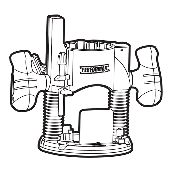
- Page 8 OVERVIEW Variable-speed dial Fine-adjustment dial ON/OFF switch Handle Handle Adjustment bar LED worklight Collet Spindle-lock button Depth-stop turret Lock nut Base plate Power indicator Motor clamp Plunge-depth locking lever Coarse-adjustment notches Dust-extraction adaptor Page 7...
- Page 9 OVERVIEW Fine-adjustment dial Slot Coarse-adjustment button Handle Handle Motor clamp Lock nut Dust-extraction adaptor Dust-extraction adaptors Pattern guide 1/4” Collet Straight-edge guide Collet wrench SPECIFICATIONS Rated voltage 120 V~ 60 Hz Rated power Input 11 A Max HP 2.0 HP Speed 11,000–25,000 RPM Collet capacity...
-
Page 10: Assembly
ASSEMBLY SELECTING THE CUTTER BIT WARNING: If any part is broken or missing, DO NOT attempt to plug in the This router comes with 1/2”collet and 1/4” power cord or operate the tool until the collet sleeve that accept cutter bits with broken or missing part is replaced. - Page 11 ASSEMBLY FIG. 2 FIG. 3 Cutters 1/4” Collet Bit shank Spindle-lock button 7. With the cutter bit inserted and the REPLACING THE CUTTER BIT spindle-lock button pressed in to engage the shaft, place the collet wrench on the CAUTION: collet nut and turn it clockwise until the Always ensure that cutter bit is firmly tightened on the collet the tool is switched OFF and unplugged...
- Page 12 ASSEMBLY INSTALLING MOTOR IN BASE INSTALLING MOTOR IN PLUNGE BASE (FIG. 5) INSTALLING MOTOR IN FIXED BASE (FIG. 4) 1. Disconnect the plug from the power supply. WARNING: Never use the router 2. Place the plunge base on a flat surface. motor without installing it into an approved 3.
- Page 13 ASSEMBLY REMOVING MOTOR FROM THE FIG. 7 PLUNGE BASE (FIG. 5) 1. Disconnect the plug from the power supply. 2. Place the router on a flat surface. 3. With the back of the plunge base facing you, open the motor clamp and make sure that the plunge action is in the “UP”...
-
Page 14: Operation
OPERATION ADJUSTING THE DEPTH OF CUT FINE ADJUSTMENTS: WARNING: Your router should NOTICE: Be sure that the worm gear never be turned on or be connected to the system is engaged before making fine power source when you are assembling adjustments. - Page 15 OPERATION DEPTH ADJUSTMENT WITH THE 5. Turn the fine-adjustment dial clockwise to lower the bit to the desired depth of PLUNGE BASE cut. Turn the dial counterclockwise to raise the cutter bit. PLUNGING ACTION (FIG. 11) 6. Once the depth of cut is set, close the motor clamp securely.
- Page 16 OPERATION PLUNGE ACTION WITH DEPTH- Depth FIG. 12 scale STOP ROD AND DEPTH-STOP TURRET (FIG. 12) Plunge-depth locking lever The depth-stop rod and the depth-stop Plastic depth turret are used to control the plunge action indicator cutting depth as follows: Depth-stop rod 1.
- Page 17 OPERATION MICRO-ADJUSTMENTS WITH • To turn the motor “ON”, push the toggle switch to the left side marked “I” and THE DEPTH-STOP ROD AND “ON.” DEPTH-STOP TURRET • To turn the motor “OFF” push the toggle switch to the right side marked The depth-stop rod has a micro-adjustment “O”...
- Page 18 OPERATION LED WORKLIGHTS (FIG. 15) HEAVY-DUTY EDGE GUIDE (FIG. 17) Your router motor has 3 built-in worklights located around the collet/nut to provide The router combo kit comes with a heavy- high visibility of the workpiece when cutting. duty edge guide. This edge guide can These lights are always “On”...
- Page 19 OPERATION EDGE ROUTING (FIG. 20) FIG. 18 Variable-speed dial 1. With the depth-of-cut set, place the router on the edge of workpiece, making sure that the cutter does not contact the workpiece. (With the plunge base, lock the plunge action in the DOWN position, ready to cut).
- Page 20 OPERATION INTERNAL ROUTING WITH WARNING: Removing the cutter bit FIXED BASE (FIG. 21) from workpiece while it is still rotating could damage the workpiece and result in loss of 1. With the depth-of-cut set, tilt the router control, causing serious personal injury. and place it on the workpiece with the leading edge of the sub-base contacting the workpiece first (FIG.
- Page 21 OPERATION FIG. 22 FIG. 23 Plunge Edge guide Feed direction WARNING: NOTICE: A core-box bit or V-groove Always securely clamp bit is often used for routing letters and the workpiece in place, and keep a firm engraving objects. Straight bits and grip on the router base with both hands at ball mills are often used to make relief all times.
- Page 22 OPERATION EDGING WITH A PILOT WHOLE EDGE SHAPING (FIG. 25) BIT (FIG. 24-25) If the workpiece is too thin or the bit is set so low that there will be no uncut edge against Arbor-type bits with pilots are excellent for which to ride the pilot, an extra board must edge shaping of any workpiece edge that be placed under the workpiece to act as...
- Page 23 OPERATION FEEDING THE ROUTER (FIG. 26) cutter bit rotation, or counterclockwise. To guard against and help prevent Kickback, plan your set-up and direction of feed so The secrets to professional routing are a that you’re always keeping the sharp edges careful set-up for the cut, selecting the of the cutter bit biting straight into uncut proper depth of cut, knowing how the cutter...
- Page 24 OPERATION DIRECTION OF FEED – INTERNAL FIG. 28 CUTS (FIG. 27-28) GUIDE INSIDE ROTATION When making an internal cut, such as a groove, dado, or slot, always try to have the GUIDE THRUST guide you are using with the router (edge guide, straight edge, board guide), on the right-hand side of the router as you make ROTATION...
- Page 25 OPERATION FEEDING TOO RAPIDLY (FIG. 29) FEEDING TOO SLOWLY (FIG. 30) Clean and smooth finished cuts can only When you feed the cutting bit too slowly, the be achieved when the cutting bit is rotating rotating cutting bit does not cut into new at a relatively high speed, taking very small wood rapidly enough to take a bite.
-
Page 26: Maintenance
MAINTENANCE Before cleaning performing 4. Insert new brush assemblies into the maintenance, verify that the router has been guide channels with the carbon part disconnected from the power supply. Keep going in first, being certain to fit the all ventilation openings clean. Avoid using two metal “ears”... -
Page 27: Troubleshooting
TROUBLESHOOTING PROBLEM CAUSE SOLUTION Plug is not plugged into the Plug the detachable cord power source. into the power source. Pull the switch to “ON” Switch is in “OFF” position. The router does not work. position. Remove the brush caps, The carbon brushes have and replace the old brushes worn out completely. - Page 28 NOTES Page 27...
- Page 29 NOTES Page 28...
- Page 30 NOTES Page 29...
-
Page 31: Warranty
2-Year Limited Warranty to the original ® purchaser. If, during normal use, this PERFORMAX® power tool breaks or fails due to a defect in material or workmanship within two (2) years from the date of original... - Page 32 © 2016 Menard, Inc., Eau Claire, WI 54703 04/2016...
Need help?
Do you have a question about the 241-1464 and is the answer not in the manual?
Questions and answers