Sign In
Upload
Download
Table of Contents
Contents
Add to my manuals
Delete from my manuals
Share
URL of this page:
HTML Link:
Bookmark this page
Add
Manual will be automatically added to "My Manuals"
Print this page
×
Bookmark added
×
Added to my manuals
Manuals
Brands
Steamist Manuals
Heater
SMS-45
Manual
Steamist SMS-4.5 Manual
Hide thumbs
Also See for SMS-4.5
:
Installation manual and owner's manual
(9 pages)
1
2
3
4
5
6
7
8
9
10
11
12
13
14
15
16
Table Of Contents
17
page
of
17
Go
/
17
Contents
Table of Contents
Troubleshooting
Bookmarks
Table of Contents
Product Information
Installation Notes
Controller Specification
Controller Information
Control Operation
Additional Features
Electrical Installation
Pre-Installation
Trouble Shooting & Error Codes
Common Trouble Shooting Solutions
Advertisement
Quick Links
1
Product Information
2
Installation Notes
3
Trouble Shooting & Error Codes
4
Common Trouble Shooting Solutions
Download this manual
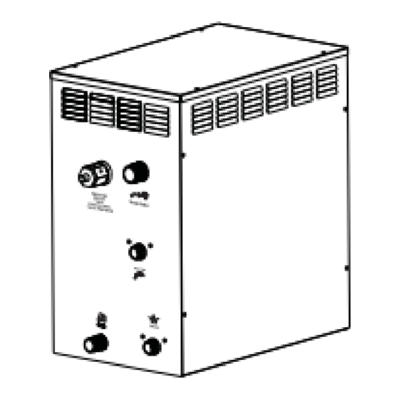
Specification, Installation and operational Manual
SMS-RANGE
For further assistance please contact
technical@steamist.co.uk
or alternatively call 02380583999
Steamist Limited, UNIT 3, M3 TRADE PARK, MANOR WAY, EASTLEIGH, SO50 9YA
Page 1
Table of
Contents
Previous
Page
Next
Page
1
2
3
4
5
Advertisement
Table of Contents
Need help?
Do you have a question about the SMS-4.5 and is the answer not in the manual?
Ask a question
Questions and answers
Related Manuals for Steamist SMS-4.5
Heater Steamist SMS-45 Installation Manual And Owner's Manual
Steamist sauna heaters (9 pages)
Heater Steamist SMS-100 Instructions For Installation And Use Manual
Floor model sauna heater (8 pages)
Heater Steamist SMS-6 Manual
(17 pages)
This manual is also suitable for:
Sms-6
Sms-9
Table of Contents
Print
Rename the bookmark
Delete bookmark?
Delete from my manuals?
Login
Sign In
OR
Sign in with Facebook
Sign in with Google
Upload manual
Upload from disk
Upload from URL


Need help?
Do you have a question about the SMS-4.5 and is the answer not in the manual?
Questions and answers