
Related Manuals for Auto Crane 600661

Summary of Contents for Auto Crane 600661
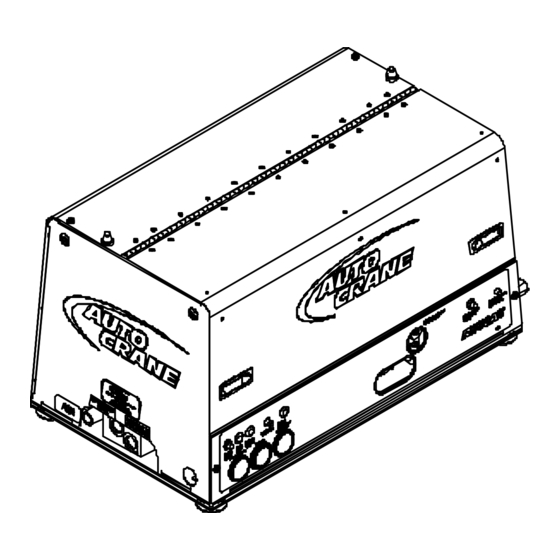
- Page 1 MODEL RS60AC AIR COMPRESSOR OPERATORS, MAINTENANCE AND PARTS MANUAL APPLIES TO SERIAL NUMBERS 600661 AND EARLIER THIS MANUAL NO LONGER REPRESENTS CURRENT PRODUCTION P/N: 304173 4/7/2010 MCM...
-
Page 2: Table Of Contents
OPERATORS, MAINTENANCE, AND PARTS MANUAL AUTO CRANE MODEL RS60AC TABLE OF CONTENTS Operation & Maintenance Section Specifications ........................6 Safety .......................... 7 - 11 Compressor Terminology ....................12 Description of Components ..................13 - 16 Inspection, Lubrication, and Maintenance ..............17 - 24 Troubleshooting ...................... -
Page 3: Specifications
SPECIFICATIONS SPECIFICATIONS SUBJECT TO CHANGE WITHOUT PRIOR NOTICE Parts List ITEM QTY PART NUMBER DESCRIPTION 200338-999 COMPR & MTG SYS, RS60AC 45/60/150 SCI8G 37 1/8 in (REV 3) [944.2 mm] 200339-999 OIL/AIR/HYD CLNG SYS, RS60AC SCI8G (REV 1) 200201-999 CANOPY SYS, RS60AC 45/60/150 SCI8G (REV 1) 200202-999 ELEC SYS, RS60AC 45/60/150 SCI8G (REV 1) 34 3/4 in... -
Page 4: Safety
SAFETY WARNING ALL UNITS ARE SHIPPED WITH A DETAILED OPERATORS AND PARTS MANUAL. THIS MANUAL CONTAINS VITAL INFORMATION FOR THE SAFE USE AND EFFICIENT OPERATION OF THIS UNIT. CAREFULLY READ THE OPERATORS MANUAL BEFORE STARTING THE UNIT. FAILURE TO ADHERE TO THE INSTRUCTIONS COULD RESULT IN SERIOUS BODILY INJURY OR PROPERTY DAMAGE. - Page 5 AUTO CRANE expressly disclaims responsibility or liability for any injury or damage caused by failure to observe these specified precautions or by failure to exercise that ordinary caution and due care required when operating or handling the Compressor, even though not expressly specified above.
- Page 6 SAFETY A compliment of warning decals is supplied with each unit. These decals must be affixed to the comressor package in the locations noted in this manual. If for any reason a safety decal is removed it is the owners responsibility to make sure it is replaced.
- Page 8 304174...
-
Page 9: Compressor Terminology
COMPRESSOR TERMINOLOGY AIR/OIL COALESCER - Performs second stage separation of oil from compressed air feeding air tools. Sometimes referred to as the separator element. CFM - Refers to the volume of compressed air being produced, expressed as cubic feet of air per minute. -
Page 10: Description Of Components
DESCRIPTION OF COMPONENTS COMPRESSOR ASSEMBLY The AUTO CRANE hydraulic drive compressor assembly is a positive displacement, oil flooded, rotary screw type unit employing one stage of compression to achieve the desired pressure. Components include a housing (stator), two screws (rotors), bearings, and bearing supports. - Page 11 DESCRIPTION OF COMPONENTS SAFETY VALVE The pop safety valve is set at 200 PSI and is located at the top of the air/oil sump. This valve acts as a backup to protect the system from excessive pressure that might result from a malfunction. AIR/OIL COALESCER The coalescer is self-contained within a spin-on housing.
- Page 12 DESCRIPTION OF COMPONENTS INSTRUMENTATION The AUTO CRANE hydraulic drive compressor unit incorporates a gauge panel that monitors temperature, pressure and hours of operation. HOURMETER The hourmeter records the total number of operating hours. It serves as a guide in following the recommended inspection and maintenance schedule.
- Page 13 DESCRIPTION OF COMPONENTS AUTOMATIC BLOW DOWN VALVE There is one blow down valve in the compressor system. It is located at the intake valve and will automatically bleed the sump to zero pressure when the compressor is disengaged. Blow down time interval takes between 45 and 60 seconds.
-
Page 14: Inspection, Lubrication, And Maintenance
INSPECTION, LUBRICATION, AND MAINTENANCE This section contains instructions for performing the inspection, lubrication, and maintenance procedures required to maintain the compressor in proper operating condition. The importance of performing the maintenance described herein cannot be over emphasized. The periodic maintenance procedures to be performed on the equipment covered by this manual are listed below. - Page 15 LUBRICATION AND MAINTENANCE CHART N " " L l i f . l i t l i t t i t l i t l i NOTE: Compressor oil and filter is to be changed after the first 50 hours of operation. After this, normal intervals are to be followed.
- Page 16 AUTO CRANE rotary screw lubricant. The lubricant supplier’s recommendation must, therefore, be based upon not only the...
- Page 17 DUE TO ENVIRONMENTAL FACTORS THE USEFUL LIFE OF ALL “EXTENDED LIFE” LUBRICANTS MAY BE SHORTER THAN QUOTED BY THE LUBRICANT SUPPLIER. AUTO CRANE ENCOURAGES THE USER TO CLOSELY MONITOR THE LUBRICANT CONDITION AND TO PARTICIPATE IN AN OIL ANALYSIS PROGRAM WITH THE SUPPLIER.
- Page 18 MAINTENANCE If some of the maintenance intervals in the schedule outlined in this manual seem to be rather short, it should be considered that one hour’s operation of a compressor is equal to about 40 road miles on an engine. Thus, eight hours operation is equal to 320 road miles, 250 hours is equal to 10,000 road miles, etc.
- Page 19 6. Run system and check for leaks. WARNING DO NOT SUBSTITUTE ELEMENT. USE ONLY A GENUINE AUTO CRANE REPLACEMENT ELEMENT. THIS ELEMENT IS RATED AT 200 PSI WORKING PRESSURE. USE OF ANY OTHER ELEMENT MAY BE HAZARDOUS AND COULD...
- Page 20 6. Add oil (total system takes one gallon), re-tighten filler cap. 7. Check for leaks in operation. WARNING DO NOT SUBSTITUTE ELEMENT. USE ONLY A GENUINE AUTO CRANE REPLACEMENT ELEMENT. USE OF ANY OTHER ELEMENT MAY BE HAZARDOUS AND COULD IMPAIR THE PERFORMANCE AND RELIABILITY OF THE COMPRESSOR, POSSIBLY VOIDING THE WARRANTY AND/OR RESULTING IN DAMAGE TO PROPERTY AND SERIOUS BODILY HARM.
- Page 21 MAINTENANCE SHAFT SEAL SHAFT SEAL INSTALLATION INSTRUCTIONS: 1. Remove hydraulic motor, drive coupling and adapter housing from face of compressor. 2. Remove coupling hub from compressor shaft. 3. Remove 4 screws from shaft seal cover and press seal out. 4. Pull seal wear sleeve off shaft with puller. 5.
-
Page 22: Troubleshooting
TROUBLESHOOTING This section contains instructions for troubleshooting the equipment following a malfunction. The troubleshooting procedures to be performed on the equipment are listed below. Each symptom of trouble for a component or system is followed by a list of probable causes of the trouble and suggested procedures to be followed to identify the cause. - Page 23 TROUBLESHOOTING IMPROPER DISCHARGE PRESSURE 1. If discharge pressure is too low, check the following: A. Too much air demand. (Air tools require more air than what the compressor can produce, air tools are free wheeling without resistance.) B. Service valve wide open to atmosphere. C.
- Page 24 TROUBLESHOOTING COALESCER PLUGGING If the coalescer element has to be replaced frequently because it is plugging up, it is an indication that foreign material may be entering the compressor inlet or the compressor oil is breaking down. Compressor oil can break down prematurely for a number or reasons. (1) Extreme operating temperature, (2) negligence in draining condensate from oil sump, (3) using the improper type of oil, (4) dirty oil, (5) oil return nozzle plugged.
-
Page 25: Compressor Operation
COMPRESSOR OPERATION Before starting the compressor, read this section thoroughly. Familiarize yourself with the controls and indicators, their purpose, location, and use. - Page 26 COMPRESSOR OPERATION OPERATING CONDITIONS The following conditions should exist for maximum performance of the compressor. The truck should be as close to level as possible when operating. The compressor will operate on a 15 degree sideward and lengthwise tilt without any adverse problems. Operation in ambient tempera- tures above 100°F (38°C) may experience high temperature shutdown.
- Page 27 PARTS AND ILLUSTRATION SECTION...
- Page 28 CONTROL HOSE PORT CALL OUTS " " FURNAS SWITCH DESCRIPTION The Furnas switch is a N.C. electrical switch set to open at 150 PSI and set to close at 115 PSI. The Furnas switch controls the N.O. regulator solenoid. If service air pressure is under 150 PSI, the Furnas switch will not trip keeping the N.O.
-
Page 35: Recommended Spare Parts
RECOMMENDED SPARE PARTS LIST " "... -
Page 36: Service Questionnaire
3. Has anyone helped you: 4. Distributor: 5. End-User: 6. Phone Number: 7. Make and Model for PTO: 8. AUTO CRANE Serial #: 9. Make and Model of Engine: 10. Engine: 11. Transmission: 12. Nature of Problem: 13. Engine RPM: 14. - Page 37 Instructional Procedures for the Installation of AUTO CRANE INFINITY Geared Rotary Screw Air Compressor This air compressor should be installed only by those who have been trained and delegated to do so and who have read and understand both the operators’ manual and the installation manual. Failure to follow the instructions, procedures, and safety precautions in this manual may result in accidents and injuries.
- Page 38 INSTRUCTIONAL PROCEDURES 2. INSTALLING THE WIRING & CONNECTING THE HYDRAULIC HOSES This unit is shipped from the factory with all necessary internal wiring installed. The only remain- ing wiring necessary is the wiring needed to interface your vehicle/power source with the AUTO CRANE compressor.
- Page 39 A. Vehicle V.I.N. B. Hydraulic Pump Data C. Air-End Serial Number D. AUTO CRANE INDUSTRIES Serial Number E. Receiver Tank Serial Number F. Note any special applications relating to specific installations. Check all fluid levels (position the unit on a level surface so that proper amount of fluids can be added).
- Page 40 INSTRUCTIONAL PROCEDURES C. Engage hydraulic system. A direction of rotation arrow is attached to the compressor pack- age above the hydraulic coupling. The coupling/hub must be rotating in the direction the arrow is pointing. If for any reason this arrow has been removed the correct compressor rotation is clockwise when looking directly at the compressor shaft.
- Page 41 The RS60AC is designed to provide continuous CFM output and constant pressure without the use of an air reservoir. Air reservoirs are not typically installed on vehicle mounted rotary screw compressors and Auto Crane does not recommend an air reservoir be in- cluded as standard equipment for use with the RS60AC compressors The above not withstanding, Auto Crane understands that some of our customers want an air reservoir installed on their vehicle in order to facilitate air usage when the vehicle’s...
- Page 42 RS60AC WITH AIR RESERVOIR APPLICATION RECOMMENDATION RS60 Compressor Check Valve Hose Reel Filter/Reg./Lubr. Vehicle Accessories Air Reservoir (if any) Drain RS60AC with Air Reservoir Schematic Recommendation...
Need help?
Do you have a question about the 600661 and is the answer not in the manual?
Questions and answers