
Related Manuals for Elsner 71190


Summary of Contents for Elsner 71190
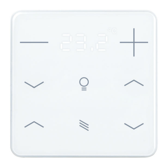
- Page 1 KNX eTR 208 Light/Sunblind Button for Temperature, Light and Solar Protection Item numbers 71190 (white), 71192 (black) Installation and Adjustment...
-
Page 3: Table Of Contents
7.8.1. AND logic outputs 1/2 and OR logic outputs 1/2 ........34 7.8.2. OR LOGIC connection inputs ..............36 Elsner Elektronik GmbH • Sohlengrund 16 • 75395 Ostelsheim • Germany KNX eTR 208 Light/Sunblind push button • from application 1.0... - Page 4 The change status (software version and date) can be found in the contents footer. If you have a device with a later software version, please check www.elsner-elektronik.de in the menu area "Service" to find out whether a more up-to- date version of the manual is available.
-
Page 5: Safety And Operating Instructions
Elsner Elektronik is not liable for any changes in norms and standards which may occur after publication of these operating instructions. For information on installation, maintenance, disposal, scope of deliv- ery and technical data, please refer to the installation instructions. -
Page 6: Area Function
Description • Operating zone for blinds, awnings, shutters or windows with 2 areas (up/ down with short/long distinction) • LEDs can be set. All LEDs Off, all LEDs as ambient lighting, all LEDs individually controllable • Area function when touching two or more push buttons. Can be configured as switch, selector switch, as 8 or 16 bit encoder or for scenario recall •... -
Page 7: Commissioning
Commissioning Configuration is made using the KNX software as of ETS 5. The product file can be downloaded from the ETS online catalogue and the Elsner Elektronik website on www.elsner-elektronik.de. After the bus voltage has been applied, the device will enter an initialisation phase last- ing approx. -
Page 8: Display And Operation At The Device
Display and operation at the device Fig. 2 View from bottom Temperature sensor Display and operation at the device 5.1. Adjust room temperature Depending on the setting of the "Display mode" parameter in the device application, the KNX eTR 208 Light/Sunblind push button displays the current room temperature value (or mixed value), the target value or the shift in relation to the basic setpoint. - Page 9 Display and operation at the device Display of the basic setpoint shift (change compared to the basic setpoint of the control): Tap +: Increase room temperature (Basic setpoint shift direction PLUS) Tap -: Lower room temperature (Basic setpoint shift direction MINUS) Option C: Display of actual temperature and target temperature/basic setpoint shift...
- Page 10 Display and operation at the device General: The step size for the change and the possible setting range are defined in the device application (ETS). There you can also define whether the manually changed values are retained after a mode change (e.g. Eco mode overnight) or reset to the stored values. The button functions can be disabled in the ETS or locked due to operating mode with priority 1.
-
Page 11: Transmission Protocol
Transmission protocol Transmission protocol Units: Temperatures in degrees Celsius 6.1. List of all communication objects Abbreviations Flags: Communication Read W Write Transmit U Update Text Function Flags DPT type Size Software version Output R-CT [217.1] DPT_Ver- 2 Bytes sion Temperature sensor: malfunction Output R-CT [1.1] DPT_Switch 1 Bit... - Page 12 Transmission protocol Text Function Flags DPT type Size Temp. thresholdV 2: (1:+ | 0:-) Input -WC- [1.1] DPT_Switch 1 Bit Temp. thresholdV 2: Switching Input -WC- [7.5] DPT_Time- 2 Bytes delay from 0 to 1 PeriodSec Temp. thresholdV 2: Switching Input -WC- [7.5] DPT_Time-...
- Page 13 Transmission protocol Text Function Flags DPT type Size Temp.control: Setpoint Eco cool- Input -WC- [1.1] DPT_Switch 1 Bit ing (1:+ | 0:-) Temp.control: Control variable Output R-CT [5.1] DPT_Scal- 1 Byte heating (level 1) Temp.control: Control variable Output R-CT [5.1] DPT_Scal- 1 Byte heating (level 2) Temp.control: Control variable...
- Page 14 Transmission protocol Text Function Flags DPT type Size LED 4 Block Input -WC- [1.1] DPT_Switch 1 Bit Area operation on/off Input -WC- [1.1] DPT_Switch 1 Bit Area operation Output: Switch Output R-CT depending on 2 Bytes setting Light switching Output R-CT [1.1] DPT_Switch 1 Bit Light dimming...
-
Page 15: Setting The Parameters
Setting the parameters Setting the parameters 7.1. Behaviour on power failure/ restoration of power Behaviour following a failure of the bus power supply: The device sends nothing. Behaviour on bus restoration of power and following programming or reset: The device sends all outputs according to their send behaviour set in the parameters with the delays established in the "General settings"... -
Page 16: Temperature Threshold Values
Setting the parameters Sending pattern for internal and total • never measured value • periodically • on change • on change and periodically At and above change of 0.1°C • 0.2°C • 0.5°C • ... • 5.0°C (if sent on change) Send cycle 5 s •... - Page 17 Setting the parameters A set threshold value will be retained until a new value or a change is transferred. The current value is saved in so that it is retained in the event of a power supply failure and will be available again once the power supply is restored. Threshold value setpoint using Parameter •...
-
Page 18: Temperature Pi Controller
Setting the parameters Block The switching output can be blocked using an object. Use switching output block No • Yes Set the cases in which threshold vlaues and delay times received per object are to be retained. Assessment of the block object •... - Page 19 Setting the parameters Comfort when present, Standby when absent, Eco as a night-time mode and Frost / heat protection (building protection) e.g. when the window is open. The settings for the temperature control include the setpoint temperatures for the in- dividual modes.
- Page 20 Setting the parameters The status object reports the current status of the output (0 = OFF, 0 = ON) and may for example be used for visualisation, or to switch off the heating pump as soon as the heating is switched off. Send status objects •...
- Page 21 Setting the parameters programming) is determined in the first section of "General controller". This also ap- plies to a comfort extension. Grading for setpoint changes 1… 50; 10 (in 0.1 °C) Storage of setpoint(s) • not be retained • after power restoration •...
- Page 22 Setting the parameters Setpoint for standby Standby mode is usually used for daytime mode when people are absent. If setpoint values are entered separately: A starting setpoint value is defined as well as a temperature range in which the setpoint value may be changed.
- Page 23 Setting the parameters If the comfort setpoint value is used as a basis: If the comfort setpoint is used as the basis, the increase/decrease of this value is indi- cated. Reduce heating setpoint (in 0.1°C) 0…200; 50 (for heating) Increase cooling setpoint (in 0.1°C) 0…200;...
-
Page 24: Heating Control Stage 1/2
Setting the parameters 7.5.1. Heating control stage 1/2 If a heating control mode is configured, one or two setting sections for the heating stages are displayed. In the first stage, heating is controlled by a PI controller which allows to either enter control parameters or select predetermined applications. - Page 25 Setting the parameters In case of a common control variable for heating and cooling, 0 is always transmitted as a fixed value. PI control with predetermined application: This setting provides fixed parameters for frequent applications. Control type • PI control Setting of the controller by •...
-
Page 26: Cooling Control Stage 1/2
Setting the parameters If separate variables are used, select whether the variable of the 2nd stage is a 1-bit ob- ject (on/off) or an 8-bit object (on with percentage value/off). Control variable is on • 1-bit object • 8-bit object Value (in %) 0...100 (for 8-bit object) - Page 27 Setting the parameters reached. You should set the time appropriate to the cooling system at this point (ob- serve manufacturer's instructions). Maximum control variable is reached 1...5 at setpoint/actual difference of (in °C) Reset time (in min.) 1...255; 30 Now specify what should be sent when the control is blocked. On release, the control variable follows the rule again.
-
Page 28: Fan Coil Control
Setting the parameters If separate variables are used, select whether the variable of the 2nd stage is a 1-bit ob- ject (on/off) or an 8-bit object (on with percentage value/off). Control variable is on • 1-bit object • 8-bit object Value (in %) 0...100 (for 8-bit object) -
Page 29: Leds
Setting the parameters Manual level after reset (only if manual 0 • 1 • 2 • 3 mode has been selected) 7.6. LEDs Set the LED mode. LED mode • All LEDs off • All LEDs as ambient lighting • All LEDs individually controllable All LEDs as ambient lighting If all LEDs are to be used as ambient lighting, illuminate all simultaneously. -
Page 30: Buttons
Setting the parameters Specify here what the LEDs for temperature display should indicate. LEDs for temperature display • display actual value only • display only target value/base shift • display actual value and target value/base shift 7.7. Buttons KNX eTR 208 Light/Sunblind has an area control, i.e. if you touch multiple buttons at the same time, you can activate another function. -
Page 31: Drive
Setting the parameters Repeat the dim command every 0.1 s • ... • every 2 s; every 0.5 s on long button press Dimming by 100% • ... • 1,5%; 6% 7.7.2. Drive If the push-button is used to control a drive, select the "blind", "awning", "shutter" or "window"... - Page 32 Setting the parameters Swap Up/Down No • Yes Control mode • Standard • Standard inverted • Comfort mode • Dead man switch Standard: Behaviour for button actuation (up): short = Stop | long = Up Behaviour for button actuation (down): short = Stop | long = Down Behaviour for button actuation (up/down): short = Stop | long = Up/Down Time between tap and hold (0.1 sec) 0 ...
- Page 33 Setting the parameters Standard: Behaviour for button actuation (retract): short = Stop | long = Retract Behaviour for button actuation (extend): short = Stop | long = Extend Behaviour for button actuation (retract/extend): short = Stop | long = Extend/Retract Time between tap and hold (0.1 sec) 0 ...
-
Page 34: Control Modes For Drive Control
Setting the parameters Standard inverted: Behaviour for button actuation (close): long = Stop | short = Close Behaviour for button actuation (open): long = Stop | short = Open Behaviour for button actuation (open/close): long = Stop | short = Open/Close Time between tap and hold (0.1 sec) 0 ... - Page 35 Setting the parameters Standard inverted: When pushed shortly, the drive moves up to the end position. When pushed for longer, the drive moves incrementally or stops. The time difference between "short" and "long" and the repeat interval is set individually. Control mode Standard inverted Behavior during button operation:...
-
Page 36: Logic
Setting the parameters Dead man's switch: The drive moves as soon as the button is actuated and stops as soon as the button is released. Control mode Dead man's switch Behavior during button operation: Push button = Up or Down command Release button = Stop command 7.8. - Page 37 Setting the parameters If the output type is a 1-bit object, set the output values for the various conditions. Output value 1 • 0 if logic = 1 Output value 1 • 0 if logic = 0 Output value 1 • 0 If block active Output value if 1 •...
-
Page 38: Or Logic Connection Inputs
Setting the parameters Block If necessary, activate the block for the logic output and set what a 1 or 0 at the block input means and what happens in the event of a block. Use block No • Yes Assessment of the block object •... - Page 40 Questions about the product? You can reach the technical service of Elsner Elektronik under Tel. +49 (0) 70 33 / 30 945-250 or service@elsner-elektronik.de We need the following information to process your service request: • Type of appliance (model name or item number) •...
Need help?
Do you have a question about the 71190 and is the answer not in the manual?
Questions and answers