Table of Contents
Advertisement
Quick Links
Carefully review assembly and care instructions before using this product. Save this document for future reference.
Assemble components on a soft, clean surface to avoid scratching or damaging the finish.
HELPFUL HINTS
Sunnydaze Decor advises reviewing this manual fully, and assembling the unit soon after purchase.
Check that all parts are accounted for and familiarize yourself with the assembly before beginning.
134130210
Purchase Date:
Thank you for choosing Sunnydaze Decor. We stand behind our brand and the quality of the items we sell.
Replacement parts or products will be sent at our discretion within the 1-year warranty period. Proof of purchase, with
the date of purchase as well as photos of the merchandise defect, must be provided. Photos are used to determine
the cause of defects and for future quality control. Register your warranty at
If you have any questions, comments or concerns, feel free to contact us by phone at 833-982-1977, by email:
customerservice@sunnydazedecor.com, or via our contact us page at
BUFFET TABLE
CRO-140
SAVE THIS MANUAL FOR FUTURE REFERENCE.
/
/
Order/Customer Reference Number:
08/2022
https://tiny.cc/SunnydazeWarranty
https://tiny.cc/SunnydazeContact
2-PERSON
ASSEMBLY
Page 1 / 14
Advertisement
Table of Contents

Related Manuals for Sunnydaze Decor CRO-140


Summary of Contents for Sunnydaze Decor CRO-140
- Page 1 Order/Customer Reference Number: Thank you for choosing Sunnydaze Decor. We stand behind our brand and the quality of the items we sell. Replacement parts or products will be sent at our discretion within the 1-year warranty period. Proof of purchase, with the date of purchase as well as photos of the merchandise defect, must be provided.
-
Page 2: Weight Capacity
INTRODUCTION Read the manual carefully to ensure you fully understand all use, care, assembly, and safety information. Assemble on a soft, flat, clean, and Read this manual carefully and dry surface. follow the assembly instructions in the order listed. Pay close Use a soft, protective barrier when attention to assembly drawings. - Page 3 COMPONENTS Part Name Qty. Bottom Inspect packaging to ensure all Right Side Panel parts are accounted for before Left Side Panel disposing of packing materials. Divider 2-PERSON Back ASSEMBLY Door Top Tube Bottom Tube Side Frame 10 Top Hardware Qty. Cam Screw Cam Lock Wood Dowel...
-
Page 4: Important Installation Information
IMPORTANT INSTALLATION INFORMATION For the stability of the unit, it is important that furniture connectors are installed correctly. See drawings and tips below for proper installation. Wood Dowel Cam Screw Cam Lock Install wood dowels by gently tapping them Use a screwdriver to tighten the cam screw Align the cam lock opening (arrow) with the into the designated hole using a rubber mallet. - Page 5 STEP 3 Parts Required IMPORTANT: Note the position of the pilot holes on Part 4; ensure components are installed as indicated in the drawing. Hardware Required Tools Required STEP 4 Parts Required IMPORTANT: Notice the distance of the pilot holes from the edges of Part 5;...
- Page 6 STEP 5 Parts Required Hardware Required Tools Required STEP 6 Parts Required Hardware Required Tools Required 134130210 08/2022 Page 6 / 14...
- Page 7 STEP 7 Gently flip the assembled unit on its side. Parts Required Hardware Required M3.5x40mm Tools Required STEP 8 Parts Required Hardware Required Tools Required 134130210 08/2022 Page 7 / 14...
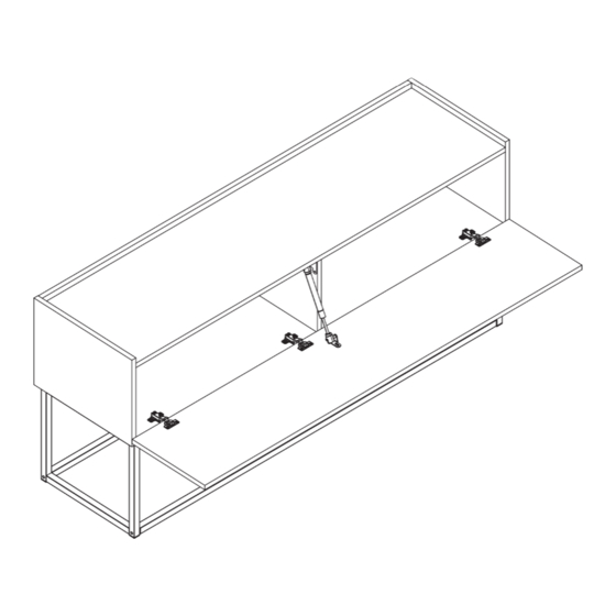
- Page 8 STEP 9 Parts Required Hardware Required M7x50mm Tools Required STEP 10 Parts Required Hardware Required M7x50mm Tools Required 134130210 08/2022 Page 8 / 14...
- Page 9 STEP 11 Parts Required Hardware Required M7x30mm Tools Required STEP 12 Parts Required Hardware Required M4x25mm Tools Required 134130210 08/2022 Page 9 / 14...
-
Page 10: Wall-Mounting Options
WALL-MOUNTING OPTIONS STEP 13 OPTION 1 Parts Required Hardware Required OPTION 1 M4x50mm OPTION 2 OPTION 2 M4x50mm Tools Required WARNING: Check for pipes and electrical wiring before drilling. IMPORTANT: Walls constructed from brick, stone, or concrete will require special fittings (not included). When in doubt, consult a qualified professional. -
Page 11: Door Installation
STEP 14 Parts Required Hardware Required M3.5x14mm IMPORTANT: The pin on the hinge slides into the slot of the hinge plate and the slot Tools Required in the hinge slides under the screw head. Slightly fasten the hinge screw to secure the components. -
Page 12: Hinge Adjustment
STEP 16 Assistance is recommended for this step. Parts Required Hardware Required Tools Required HINGE ADJUSTMENT Please note, care must be taken during hinge adjustment to avoid damage. Only slight adjustment is required. Rotate the Door Adjustment screws 1/8 to 1/4 turns at a time, then check the door position. Rotate adjustment screws as necessary until doors are properly aligned. - Page 13 STEP 17 Parts Required Hardware Required M3.5x14mm Tools Required STEP 18 Parts Required Hardware Required 134130210 08/2022 Page 13 / 14...
- Page 14 SAFETY STATEMENTS & WARNINGS • For residential use only. Not for commercial or industrial use. • For indoor use only. • Ensure all fittings are tight before use. Periodically check fittings to ensure they are tight. • Only use this unit on a flat, level surface. •...
Need help?
Do you have a question about the CRO-140 and is the answer not in the manual?
Questions and answers