Table of Contents
Advertisement
Quick Links
Advertisement
Table of Contents
Troubleshooting

Related Manuals for ubiquoss E3208E

Summary of Contents for ubiquoss E3208E
- Page 1 E3208E Installation Guide...
- Page 2 E3208E Installation Guide ubiQuoss Inc. 24F Millennium B/D, 467-12 Dogok-Dong Gangnam-Gu, Seoul 135-700 Korea TEL: +82-70-8666-5000 FAX: +82-2-2190-3201 E-mail: oversea.team@ubiQuoss.com www.ubiQuoss.com...
- Page 3 Preface This preface provides the overview of E3208E installation guide, which describes guide conventions, and lists other publications that may be useful. Introduction This manual is to describe how to install ubiQuoss E3208E Switch. This manual is the hardware installation guide for installing and connecting E3208E Switch.
- Page 4 Preface Symbols in this Guide The symbols below are used to indicate the product names and notes in the user guide. Description of Symbols The installation guide uses the following icons and fonts to indicate special messages for the reader. Note Presents the useful contents related to the user guide, the references and data related to the product use, etc.
- Page 5 Chapter 3. Installation This chapter describes how to install E3208E Switch on a rack and connect each port of the switch. Chapter 4. Troubleshooting This chapter describes the troubles that may occur during installation or use of E3208E, and explains how to solve the problems.
-
Page 6: Table Of Contents
Table of Content Table of Content Preface.......................... III Introduction........................III Related Documents ......................III Product Name........................III History of Document ......................III Symbols in this Guide......................IV Organization ........................V Table of Content......................VI List of Figure and Table ....................VIII List of Figure ......................... - Page 7 Specification........................32 Appendix B. Cable Spec................33 Ethernet cable.........................34 Optical cable ........................34 Console cable .........................35 E3208E Installation Guide...
-
Page 8: Introduction
List of Figure and Table List of Figure and Table Table 1 Console port Specification................. 14 Table 2 System status LED..................15 Table 3 Port status LED ..................15 Table 4 List of Package Items ................22 Table 5 Specification ....................32 Table 6 Configuration of terminal mode .............. -
Page 9: List Of Figure
<Figure 7> E3208E ONU Real Panel ..............16 <Figure 8> RST button ..................16 <Figure 9> E3208E ONU Right / Left Side ............17 <Figure 10> Connecting AC power cable, DC power lines, and Grounding Cable.25 <Figure 11> Diagram of Console Cable ..............35... -
Page 11: Chapter 1. Introduction
Chapter 1. Introduction This chapter describes the types and features of E3208E and explains the name and function of each part. This chapter consists of the following sections. Features of Product Appearance of Product E3208E Installation Guide... -
Page 12: Overview
It can be also deployed economically because it is based on 100Mbps downlink speed as FE and an uplink port as GE-PON. E3208E is the best solution for medium size networks with high traffic volumes. E3208E also provides advanced network management and switching functions that follow the global standard. -
Page 13: Features
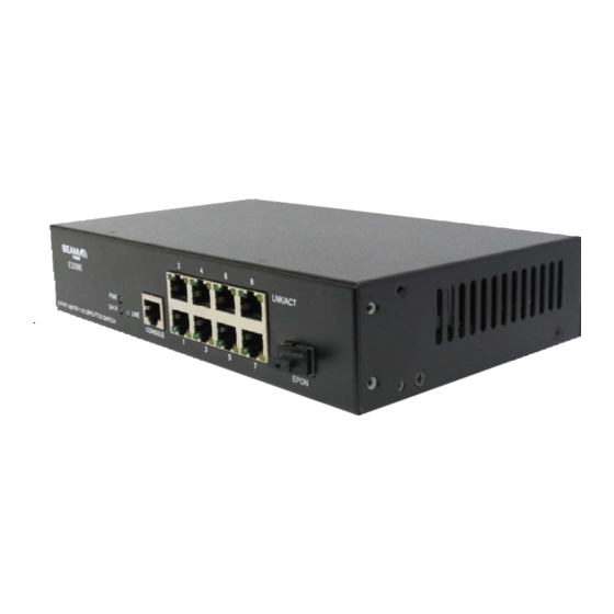
Features Front View This section describes the name and function of each part on the front panel of E3208E. <Figure 1> E3208E ONU Front View The front panel has console port (RJ-45 Type), Fast Ethernet 10/100B-T 8 ports, E-PON Up- link, and LEDs for system status. -
Page 14: Figure 3> Leds And Console Port
<Figure 3> LEDs and Console Port <Figure 4> Console Port Pin numbers The console port is used to connect a console terminal to manage E3208E. The console cable (Serial Cable) that is used to connect between the console port and a console terminal comes with the product. -
Page 15: Figure 5> System Status Led
System status LED <Figure 5> System Status LED E3208E provides various system status LEDs that shows the power supply status and so on. System status LED works as follows based on the system status. Table 2 System status LED System status LED... -
Page 16: Rear View
<Figure 7> E3208E ONU Real Panel RST Button <Figure 8> RST button E3208E has a reset button on the side of the system so that the user can manually reboot the system by pressing the RESET button. Note Please use a pen or thin material, and press the reset button gently. -
Page 17: Side View
Side View Air Flow The vent hole is the part required for air intake or outtake to prevent the Switch from getting overheated. <Figure 9> E3208E ONU Right / Left Side E3208E Installation Guide... -
Page 18: Chapter 2. Installation Preparation
Chapter 2. Installation Preparation This chapter describes the necessary items to install E3208E Switch and the notes to take about installing and using the product. The user should fully understand the notes in this chapter before installing the product to prevent any problem from occurring during the product installation. -
Page 19: Pre-Installation Checklist
Pre-installation Checklist Before installing and using E3208E Switch, please read this section carefully and follow the instructions. Do not disassemble the product The user should not disassemble the product. If the user thinks that a repair is necessary, contact the Ubiquoss Technical Support Team. -
Page 20: Requirements For Handling Power
Always check the working place for the possibility of any danger, the wet floor, non- grounded power extension cable, the floor with no grounding facility, etc. When connecting the AC power of E3208E, use the grounding-type plug and the properly-grounded power. ... -
Page 21: Grounding
When you see the following symbol label in the system module, you must take care to ensure that any laser light escaping is not directed towards the eyes. Figure 1. Warning Label According to IEC 60825/EN 60825 E3208E Installation Guide... -
Page 22: Items Required For Installation
Items Required for Installation Items Required for Installation To install the E3208E Switch, the following items are required. The items marked with * are not supplied together with the product. The user needs to prepare those items. E3208E ONU Main Body ... -
Page 23: Chapter 3. Installation
Chapter 3. Installation This chapter describes how to install E3208E Switch on a rack and connect each port of the switch. This chapter consists of the following sections. Selecting Installation Place Connecting Power Connecting Console Terminal ... -
Page 24: Installation Procedure
Installation Procedure Installation Procedure Selecting Installation Place The E3208E should be installed on a place that meets the following conditions to use the product safely and stably: Avoid the location where temperature is too high or too low. Especially avoid the place exposed to direct ray of light or near heater) ... -
Page 25: Battery Operating
DB-9 connector (the other side of the cable) to the console terminal. The terminal device used as the console terminal of E3208E should be set according to the following communication configuration in order to communicate with E3208E normally. - Page 26 Installation Procedure Note Most of the cases that the screen display of the console terminal fails, it is due to the wrong setting of the number of bits per sec in the console terminal. In case that the characters on the console terminal screen are broken or that no character is displayed, check the number of bits per sec set in the terminal.
-
Page 27: Connecting Epon Up-Link Port
Connecting EPON Up-Link port E3208E ONU provides Gigabit EPON Up-Link that supports 1.25Gbps speed. EPON –Up- Link port supports 1000 Base-PX10-ONU and it uses optical cable that has SC connector. The instruction on connecting the cable to the port is given below. - Page 28 Connecting EPON Up-Link port Once the initialization is successfully completed, a login: message appears. In this status, the user can log in to the CLI of the equipment to configure the equipment. After system boots, in case that console terminal connects the system, click [Enter] key. Then you can see login: massage.
-
Page 29: Chapter 4. Troubleshooting
Chapter 4. Troubleshooting This chapter describes the troubles that may occur during installation or use of E3208E, and explains how to solve the problems. Many of the problems occurred to the equipment can be easily checked and solved by the user. -
Page 30: Troubleshooting Case
Troubleshooting Case Troubleshooting Case [Problem 1] POWER LED is not turned ON. The power is not supplied normally.. Solution 1. Check if the power cable is properly connected to the power input terminal of the equipment. 2. Check the power supply status of the power outlet that the power cable is connected to. - Page 31 SFP port again. 3. Check if the optic cable used in the SFP port is made as specified in Appendix B. 4. Check if the connected equipments are working properly. E3208E Installation Guide...
-
Page 32: Appendix A. Product Specification
Troubleshooting Case Appendix A. Product Specification Appendix A describes the product specifications of E3208E. Specification Table 5 Specification Item Specification Physical Dimension Dimension (W x D x H) 220.2mm x 126.2mm x 43.2mm Standard 19 inch Rack mountable or Wall mountable Weight Max. -
Page 33: Appendix B. Cable Spec
Appendix B. Cable Spec Appendix B describes the specification of cables used to connect the ports of E3208E in detail. This Appendix B consists of the following sections. Ethernet cable Optic cable Console cable Note The standards of various Ethernet ports on the front panel of E3208E are as follows. -
Page 34: Ethernet Cable
Troubleshooting Case Ethernet cable E3208E ONU use the UTP Cable having RJ-45 connectors at both ends. Use the following category cables for Twisted-pair cable depending on the speed of the equipments to be connected. 10B-T : Category 3 , 5 , 5E , 6 ... -
Page 35: Console Cable
Table 6 Configuration of terminal mode Pin Number Pin Number Signal Definition of Pin (Console port) (Console terminal) Transmit Data Receive Data Signal Ground Terminal Side RS232C Connector Switch side RS232C Connector <Figure 11> Diagram of Console Cable E3208E Installation Guide...
Need help?
Do you have a question about the E3208E and is the answer not in the manual?
Questions and answers