
Subscribe to Our Youtube Channel
Related Manuals for Oerlikon CENTER TWO

Summary of Contents for Oerlikon CENTER TWO
- Page 1 sales@artisantg.com artisantg.com (217) 352-9330 | Visit our website - Click HERE...
- Page 2 CENTER TWO CENTER THREE Multi-Channel Controller Operating Manual GA 09.035/6.02 Cat. No. 230 003 230 004 235 003 235 004...
-
Page 3: Table Of Contents
Communication ........58 GA 09.035/6.02 - 07/2011 - © Oerlikon Leybold Vacuum... - Page 4 Index ..........95 GA 09.035/6.02 - 07/2011 - © Oerlikon Leybold Vacuum...
-
Page 5: Introduction
There is a type label attached to one side of the unit. In all communication with Oerlikon Leybold Vacuum, please state the information on the type label. For this purpose you may want to copy the information into the space provided below: Fig. -
Page 6: Intended Use
Introduction Intended use The CENTER TWO and CENTER THREE Multi-Channel Controller is a dis- play and control unit for transmitters made by Oerlikon Leybold Vacuum. It is used together with transmitters of the THERMOVAC, PENNINGVAC, CERAVAC and IONIVAC series and is used for total pressure measurements. -
Page 7: Safety
«Caution» indicates a potentially hazardous situation which, if not avoided, Caution may result in moderate or minor injury or in property damage. Note: A note such as this one indicates particularly important, but not safety- relevant information. GA 09.035/6.02 - 07/2011 - © Oerlikon Leybold Vacuum... - Page 8 Use the Multi-Channel Controller only as intended by the manufacturer. See Chapter 1.2 Intended use, Improper installation and operation data. Caution Improper installation and operation data may damage the Multi-Channel Controller. Strictly adhere to the stipulated installation and operation data. GA 09.035/6.02 - 07/2011 - © Oerlikon Leybold Vacuum...
- Page 9 The disconnecting device must be readily identifiable and easily reached by the user. In order to disconnect the Multi-Channel Controller from mains, you must unplug the mains cable. Fig. 1-3 Back side of the CENTER THREE A Disconnecting device GA 09.035/6.02 - 07/2011 - © Oerlikon Leybold Vacuum...
-
Page 10: Technical Data
See Fig. 2-1, Weight CENTER TWO: 1.04 kg CENTER THREE: 1.16 kg Desktop unit Control panel mounted Mounting the unit in a rack 106.3 91.4 204.5 Fig. 2-1 Dimensions (in mm) GA 09.035/6.02 - 07/2011 - © Oerlikon Leybold Vacuum... -
Page 11: Mains Connection
Mains connection Voltage 90…250 VAC Frequency 50…60 Hz Power consumption CENTER TWO: Max. 45 W CENTER THREE: Max. 65 W Overvoltage category Protection class Connection European appliance connector IEC 320 C14 GA 09.035/6.02 - 07/2011 - © Oerlikon Leybold Vacuum... -
Page 12: Channels
Display rate 10 s Filter time constant Slow: Approx. 1.0 s (f = 0.16 Hz) Normal (nor): Approx. 0.3 s (f = 0.53 Hz) Fast: Approx. 0.06 s (f = 2.65 Hz) GA 09.035/6.02 - 07/2011 - © Oerlikon Leybold Vacuum... -
Page 13: Switching Functions
Change-over contact, floating Load (ohmic) Max. 60 VDC, 0.5 A Max. 30 VAC, 1 A Lifetime Mechanical: cycles Electrical: cycles at maximum load Connection D-Sub, 25 pins, female. See Fig. 3-8, GA 09.035/6.02 - 07/2011 - © Oerlikon Leybold Vacuum... -
Page 14: Outputs
Number Voltage range 0…10 VDC Resolution 1 mV Accuracy ± 20 mV 3300 Ω Internal resistance Relation between voltage and pres- Programmable sure Connection D-Sub, 9 pins, male. See Fig. 3-9, GA 09.035/6.02 - 07/2011 - © Oerlikon Leybold Vacuum... -
Page 15: Scope Of Delivery
Scope of delivery Designation Number Multi-Channel Controller Mains cable Rubber strip Rubber feet Collar screws Plastic sleeves Accessories Designation Product number D-Sub plug for the CONTROL con- 230 006 nection, screwon type GA 09.035/6.02 - 07/2011 - © Oerlikon Leybold Vacuum... -
Page 16: Installation
Turn the Multi-Channel Controller upside down as shown in Fig. 3-1, Push the supplied rubber strip onto the lower edge of the front panel Stick the supplied rubber feet to the bottom of the casing GA 09.035/6.02 - 07/2011 - © Oerlikon Leybold Vacuum... - Page 17 Insert the Multi-Channel Controller into the cutout Fasten the unit with four M3 screws Note: In order to reduce the strain on the front panel it is recommended to sup- port the bottom of the unit. GA 09.035/6.02 - 07/2011 - © Oerlikon Leybold Vacuum...
- Page 18 Fasten the rack chassis adapter in the rack Insert the Multi-Channel Controller into the rack chassis adapter Fasten the Multi-Channel Controller with the supplied collar screws and plastic sleeves to the rack chassis adapter GA 09.035/6.02 - 07/2011 - © Oerlikon Leybold Vacuum...
-
Page 19: Connecting
Back side of the device Fig. 3-4, 18 shows the back side of the CENTER THREE. The connection for channel 3 (item C) is not available in the CENTER TWO. Fig. 3-4 Back side of the CENTER THREE A Transmitter connection, channel 1... - Page 20 18, item I) can be used to connect the Multi- Channel Controller with the protective ground of the pumping station. If required: Connect the protective ground of the pumping station with the ground screw. Use a protective conductor. GA 09.035/6.02 - 07/2011 - © Oerlikon Leybold Vacuum...
- Page 21 Chapter 2.3.1 Sensor connections, Multiple connection. Caution Only one Transmitter may be connected to each of the channels. Other- wise the connected transmitters will be damaged. Never connect more than one transmitter per channel. GA 09.035/6.02 - 07/2011 - © Oerlikon Leybold Vacuum...
- Page 22 Pin 25 is used for supplying relays with a higher breaking capacity. The supply contact is protected at 200 mA with a PTC element. The element is self-resetting when switching the unit off or unplugging the RELAY connector. GA 09.035/6.02 - 07/2011 - © Oerlikon Leybold Vacuum...
- Page 23 Connect the peripheral components with the CONTROL connection. Use a shielded connection cable. Note: The analog outputs (pins 1, 2, 6) differ from the displayed values by no more than ±50 mV. GA 09.035/6.02 - 07/2011 - © Oerlikon Leybold Vacuum...
- Page 24 Connect the serial interface of the computer with the RS232C connec- tion. Use a shielded cable. Note: Use a serial extension cable with a 9-pin plug and a 9-pin socket. The ca- ble must not contain any crossed wires. GA 09.035/6.02 - 07/2011 - © Oerlikon Leybold Vacuum...
-
Page 25: Operation
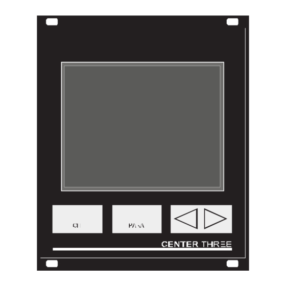
A Switching function indicator B Parameter mode C Pressure unit D Display area for channel 1 E Display area for channel 2 F Display area for channel 3 G Control buttons GA 09.035/6.02 - 07/2011 - © Oerlikon Leybold Vacuum... - Page 26 The arrow buttons are required for entering data in the parameter mode. Pressing one of these buttons will decrease or increase the currently displayed value. In the following, these buttons will be referred to as DOWN and UP, respectively. GA 09.035/6.02 - 07/2011 - © Oerlikon Leybold Vacuum...
-
Page 27: Switching On And Off
Wait for at least 10 seconds before you switch the Multi-Channel Controller on again. Note: If the Multi-Channel Controller has been installed in a control panel or a rack, it can also be switched on and off via the central power distributor. GA 09.035/6.02 - 07/2011 - © Oerlikon Leybold Vacuum... -
Page 28: Operating Modes
When the unit is set to the parameter mode, it will automatically return to the measurement mode if no button is pressed for 10 seconds. GA 09.035/6.02 - 07/2011 - © Oerlikon Leybold Vacuum... - Page 29 See Chapter 5.2.8, CH 3 See Chapter 5.4.5, Tab. 4-1 Display when in measurement mode Channels which are not connected to a transmitter display noSEn. This status message disappears after approximately two minutes. GA 09.035/6.02 - 07/2011 - © Oerlikon Leybold Vacuum...
- Page 30 Pressing the PARA button The unit changes to the parameter mode. See Chapter 4.5 Parameter mode, 33. It will automatically return to the measurement mode if no button is pressed for 10 seconds. GA 09.035/6.02 - 07/2011 - © Oerlikon Leybold Vacuum...
- Page 31 Press the CH button to select the required channel Keep the UP button pressed for approximately 1 second. See Fig. 4-4, The degas function of the transmitter on the selected channel is switched on. The DEG indicator is illuminated. GA 09.035/6.02 - 07/2011 - © Oerlikon Leybold Vacuum...
- Page 32 Press the CH button to select the required channel Keep the DOWN button pressed for approximately 1 second. See Fig. 4-5, The degas function of the transmitter on the selected channel is switched off. The DEG indicator is dark. GA 09.035/6.02 - 07/2011 - © Oerlikon Leybold Vacuum...
- Page 33 No transmitter found noSEn No transmitter identification found noid Tab. 4-2 Transmitter identification Note: In the case of ITR transmitters, the software version number of the sen- sor is also shown (e.g. 1.20). GA 09.035/6.02 - 07/2011 - © Oerlikon Leybold Vacuum...
-
Page 34: Parameter Mode
34 shows all available parameters. Parameter group Parameters PArA SP1-L SP1-H SP2-L SP2-H SP3-L SP3-H SP4-L SP4-H SP5-L SP5-H SP6-L SP6-H PArA FiLt dEGAS S-on S-oFF PArA unit bAud diGit Err-r GA 09.035/6.02 - 07/2011 - © Oerlikon Leybold Vacuum... - Page 35 This parameter group is used to check individual system functions. The parameter group is not required during normal operation. For this reason it must be accessed in a special way. See Chapter 5.4 Test parameters (PArA tESt), GA 09.035/6.02 - 07/2011 - © Oerlikon Leybold Vacuum...
- Page 36 The unit returns to the measurement mode after the last parameter of a parameter group has been accessed. Parameter modifications are effective immediately, and they are saved in the EEPROM automatically. GA 09.035/6.02 - 07/2011 - © Oerlikon Leybold Vacuum...
-
Page 37: Parameters
5.1.1 Fundamental terms Switching functions The CENTER TWO is equipped with four relays which switch in dependance of the measured pressure. The relay contacts are potential-free and can be used for switching via the RELAY connection. See Chapter 3.3.5 RELAY, 21. - Page 38 Use the arrow buttons to modify the threshold value The value of the parameter is changed Repeat the steps 1 to 3 to change further parameters of the same parameter group GA 09.035/6.02 - 07/2011 - © Oerlikon Leybold Vacuum...
- Page 39 (logarithmic transmitters) or to 1 % of the full-scale range (linear transmitters) at least. If another transmitter type is connected to a channel, the respective threshold values will be adjusted automatically if necessary. GA 09.035/6.02 - 07/2011 - © Oerlikon Leybold Vacuum...
-
Page 40: Sensor Parameters (Para Sen)
The filter affects the readings on the display, the RS232C output, the recorder output, and the switching functions. The analog outputs, how- ever, are not affected. The filter can be set to one of the following values: GA 09.035/6.02 - 07/2011 - © Oerlikon Leybold Vacuum... - Page 41 Slow. The Multi-Channel Controller responds slowly to signal changes. This makes it less sensitive to signal noise. This setting is recommended for pre- cise comparison measurements. Fig. 5-4 Measurement with filter set to SLo (example) GA 09.035/6.02 - 07/2011 - © Oerlikon Leybold Vacuum...
- Page 42 For transmitters of type ITR und PTR 90, the gas type correction is effec- tive only for p < 10 mbar; in case of TTR100 and TTR 101 only for p < 10 mbar. GA 09.035/6.02 - 07/2011 - © Oerlikon Leybold Vacuum...
- Page 43 Select the oFS parameter Press the DOWN button The offset correction is deactivated The display shows oFF The OFS indicator is dark Activating the offset correction Select the oFS parameter Press the UP button GA 09.035/6.02 - 07/2011 - © Oerlikon Leybold Vacuum...
- Page 44 You may also deactivate this function manually. Deactivating the degas function Select the dEGAS parameter Press the DOWN button The degas function is deactivated The display shows oFF The DEG indicator is dark GA 09.035/6.02 - 07/2011 - © Oerlikon Leybold Vacuum...
- Page 45 CH 1 By channel 1. The subsequent parameter t-off is used to specify the switch-off threshold. The transmitter is switched off when the pressure on channel 1 exceeds the switch-off threshold. GA 09.035/6.02 - 07/2011 - © Oerlikon Leybold Vacuum...
- Page 46 This parameter defines the rules for selecting the active filament. Display Significance The transmitter alternately selects one of the two Auto filaments Filament 1 ist active Fil 1 Filament 2 ist active Fil 2 Tab. 5-7 parameter values GA 09.035/6.02 - 07/2011 - © Oerlikon Leybold Vacuum...
- Page 47 Extend the display and the setpoint adjustment range. Display Significance Normal operation Range extension: Display down to 5 × 10 mbar Setpoint adjustment range down to 2 × 10 mbar Tab. 5-8 parameter values GA 09.035/6.02 - 07/2011 - © Oerlikon Leybold Vacuum...
-
Page 48: General Parameters (Para Gen)
See Chapter 5.4.4 Torr lock (tr-L), 5.3.2 Baud rate (bAud) Transfer rate of the RS232C interface. Display Significance 9600 Baud 9600 19200 Baud 19200 38400 Baud 38400 Tab. 5-10 bAud parameter values GA 09.035/6.02 - 07/2011 - © Oerlikon Leybold Vacuum... - Page 49 Use the CH button to assign the recorder output to a channel Use the arrow buttons to select the characteristic curve of the output The value of the parameter is changed GA 09.035/6.02 - 07/2011 - © Oerlikon Leybold Vacuum...
- Page 50 = 10^[(U - 7.75)/0.75] ITR 200 p = 10^[U - 8] LoG -6 Logarithmic representation of a partial measurement range (2.5 V/decade). Transmitter Pressure (in mbar) All types p = 10^[U/(10/4) - 10] GA 09.035/6.02 - 07/2011 - © Oerlikon Leybold Vacuum...
- Page 51 The total measuring range of the sensor combination is repre- sented logarithmically in the range 0…10 V. Note: The three transmitters must be sorted with regard to their measuring range (FS). The sort order may be increasing or decreasing. GA 09.035/6.02 - 07/2011 - © Oerlikon Leybold Vacuum...
- Page 52 All errors Device errors no SE Sensor 1 and device errors CH 1 Sensor 2 and device errors CH 2 Sensor 3 and device errors CH 3 Tab. 5-12 Err-r parameter values GA 09.035/6.02 - 07/2011 - © Oerlikon Leybold Vacuum...
-
Page 53: Test Parameters (Para Test)
PARA button repeatedly until all test parameters have been run through. 5.4.2 Firmware version (Pnr) Displays the firmware version number. The last character represents the mod- ification index. Example: 302-533-F GA 09.035/6.02 - 07/2011 - © Oerlikon Leybold Vacuum... - Page 54 This parameter affects the parameter mode. When the lock is activated, the user can inspect but not modify parameter values. Display Significance Parameters can be inspected and modified Parameters can be inspected only Tab. 5-15 LoC parameter values GA 09.035/6.02 - 07/2011 - © Oerlikon Leybold Vacuum...
- Page 55 Test is running Test completed without errors PASS Test completed and errors detected Tab. 5-16 RAM test Please contact your local Oerlikon Leybold Vacuum service center if the test fails repeatedly. 5.4.7 EPROM test (EP-t) Test the program memory. Press the UP button to start the test.
- Page 56 Switching function 1 relay off r1-L Switching function 2 relay on r2-H Switching function 2 relay off r2-L Switching function 3 relay on r3-H Switching function 3 relay off r3-L GA 09.035/6.02 - 07/2011 - © Oerlikon Leybold Vacuum...
- Page 57 Multi-Channel Controller. The data transfer between the two units is visible on the terminal screen only. Press the PARA button to quit the test and to return to the measurement mode. GA 09.035/6.02 - 07/2011 - © Oerlikon Leybold Vacuum...
-
Page 58: Computer Interface
<ENQ> Enquiry (Ctrl-E). Request data transmission. <ACK> Acknowledge. Positive acknowledge. <LF> Line feed. Line feed. <CR> Carriage return. Carriage return. <NAK> Negative acknowledge. Negative acknowledge. Tab. 6-2 Control characters GA 09.035/6.02 - 07/2011 - © Oerlikon Leybold Vacuum... -
Page 59: Communication
S: <ENQ> R: Data<CR><LF> If the Multi-Channel Controller receives a message which cannot be inter- preted (syntax error) it stores the respective error status in the output buffer. See Chapter 6.3.9 ERR, GA 09.035/6.02 - 07/2011 - © Oerlikon Leybold Vacuum... - Page 60 R: <ACK><CR><LF> S: <ENQ> R: 0,9.0000E-01,2.2000E+00<CR><LF> Setting the filter S: FIL,1,2,1<CR>[<LF>] R: <ACK><CR><LF> S: <ENQ> R: 1,2,1<CR><LF> Behavior in case of a syntax error S: FOL,1,2,1<CR>[<LF>] R: <NAK><CR><LF> S: <ENQ> R: 0001<CR><LF> GA 09.035/6.02 - 07/2011 - © Oerlikon Leybold Vacuum...
- Page 61 By default one set of measurements is sent every second. The continuous measurement transmission stops when the Host sends a character to the serial interface. The transmission can be resumed with the COM command. See Chapter 6.3.4 COM, GA 09.035/6.02 - 07/2011 - © Oerlikon Leybold Vacuum...
-
Page 62: Mnemonics
Pressure sensor 2. Pressure reading of transmitter 2. Pressure sensor 3. Pressure reading of transmitter 3. Pirani range extension. Pressure sensors. Pressure readings of all transmitters. Reset. Reset the serial interface. GA 09.035/6.02 - 07/2011 - © Oerlikon Leybold Vacuum... - Page 63 Test I/O. Test the relays. Test keyboard. Test the keyboard. Torr lock. Test RAM. Test the RAM. Test RS232C interface. Test the RS232C interface. Unit of measurement. Watchdog control. Tab. 6-3 Mnemonics GA 09.035/6.02 - 07/2011 - © Oerlikon Leybold Vacuum...
- Page 64 18 = Linear Lin -1 19 = Linear Lin +0 20 = Linear Lin +1 21 = Linear Lin +2 22 = Linear Lin +3 23 = iM221 24 = Logarithmic LoGC4 25 = PM411 GA 09.035/6.02 - 07/2011 - © Oerlikon Leybold Vacuum...
- Page 65 3 = Transmitter error 4 = Transmitter switched off 5 = No Transmitter 6 = Identification error 7 = ITR error ±c.ccccE±cc Reading of transmitter 1 in current unit of mea- surement GA 09.035/6.02 - 07/2011 - © Oerlikon Leybold Vacuum...
- Page 66 Correction factor of channel 2 (see above) c.cc Correction factor of channel 3 (see above) Note: The correction factor is only used when the gas type is set to «Other gas». See Chapter 6.3.14 GAS, GA 09.035/6.02 - 07/2011 - © Oerlikon Leybold Vacuum...
- Page 67 0 = Degassing off (default) 1 = Degassing on Transmitter 2 (see above) Note: The degas function is switched off automatically after 3 minutes. It may be also be stopped prematurely. GA 09.035/6.02 - 07/2011 - © Oerlikon Leybold Vacuum...
- Page 68 0010 = Parameter invalid 0001 = Syntax error Note: The error status is a binary number. It may be combined by the logical operator OR. Example: 1001 = Device error and syntax error. GA 09.035/6.02 - 07/2011 - © Oerlikon Leybold Vacuum...
- Page 69 (see above) Filter for channel 3 (see above) 6.3.12 Full scale range. Full scale range of linear transmitters (CTR, DI). See Chapter 5.2.3 Measuring range (FS), S: FSR[,a,b,c]<CR>[<LF>] R: <ACK><CR><LF> S: <ENQ> GA 09.035/6.02 - 07/2011 - © Oerlikon Leybold Vacuum...
- Page 70 34 = 50 bar 35 = DI200 mbar 36 = DI2 bar 37 = DI2 bar relative Full scale range of transmitter 2 (see above) Full scale range of transmitter 3 (see above) GA 09.035/6.02 - 07/2011 - © Oerlikon Leybold Vacuum...
- Page 71 Gas type for channel 3 (see above) Note: When «Other gas» is selected, the gas type dependence of the measure- ments will be corrected by a variable correction factor. See Chapter 6.3.5 COR, GA 09.035/6.02 - 07/2011 - © Oerlikon Leybold Vacuum...
- Page 72 S: ITR<CR>[<LF>] R: <ACK><CR><LF> S: <ENQ> R: aa,aa,aa,aa,aa,aa,aa,aa bb,bb,bb,bb,bb,bb,bb,bb cc,cc,cc,cc,cc, cc,cc<CR><LF> Parameters Significance aa,aa,aa,aa,aa,aa,aa,aa Data string of transmitter 1 bb,bb,bb,bb,bb,bb,bb,bb Data string of transmitter 2 cc,cc,cc,cc,cc,cc,cc,cc Data string of transmitter 3 GA 09.035/6.02 - 07/2011 - © Oerlikon Leybold Vacuum...
- Page 73 2 = Determine the offset value and activate offset correction function 3 = Adjust the zero point of a CTR 100/CTR101 Offset correction of channel 2 (see above) Offset correction of channel 3 (see above) GA 09.035/6.02 - 07/2011 - © Oerlikon Leybold Vacuum...
- Page 74 Offset value of transmitter 3 in current unit of measurement (see above) 6.3.20 Program number. Firmware version number. See Chapter 5.4.2 Firmware ver- sion (Pnr), S: PNR<CR>[<LF>] R: <ACK><CR><LF> S: <ENQ> R: a<CR><LF> Parameters Significance Firmware version Example: 302-533-F GA 09.035/6.02 - 07/2011 - © Oerlikon Leybold Vacuum...
- Page 75 S: <ENQ> R: a,b,c<CR><LF> Parameters Significance Range extension for transmitter 1 0 = Off (default) 1 = On Range extension for transmitter 2 (see above) Range extension for transmitter 3 (see above) GA 09.035/6.02 - 07/2011 - © Oerlikon Leybold Vacuum...
- Page 76 Deletes the input buffer. All queued error messages are sent to the Host. The unit returns to the measurement mode. S: RES[,a]<CR>[<LF>] R: <ACK><CR><LF> S: <ENQ> R: b,c,d,...<CR><LF> Parameters Significance 1 = Perform reset GA 09.035/6.02 - 07/2011 - © Oerlikon Leybold Vacuum...
- Page 77 0 = Save default parameters 1 = Save user parameters Note: Parameters which have been changed manually (control buttons) are saved in the EEPROM automatically. The SAV command is not required in this case. GA 09.035/6.02 - 07/2011 - © Oerlikon Leybold Vacuum...
- Page 78 Setpoint 1. Switching function 1. See Chapter 5.1 Switching function parame- ters (PArA SP), S: SP1[,a,b.bbbbE±bb,c.ccccE±cc]<CR>[<LF>] R: <ACK><CR><LF> S: <ENQ> R: a,b.bbbbE±bb,c.ccccE±cc<CR><LF> Parameters Significance Switching function assignment 0 = Channel 1 1 = Channel 2 2 = Channel 3 GA 09.035/6.02 - 07/2011 - © Oerlikon Leybold Vacuum...
- Page 79 Status of switching function 2 (see above) Status of switching function 3 (see above) Status of switching function 4 (see above) Status of switching function 5 (see above) Status of switching function 6 (see above) GA 09.035/6.02 - 07/2011 - © Oerlikon Leybold Vacuum...
- Page 80 0.0000…+5.0000 6.3.30 Test display. Test the display. See Chapter 5.4.9 Display test (di-t), S: TDI[,a]<CR>[<LF>] R: <ACK><CR><LF> S: <ENQ> R: a<CR><LF> Parameters Significance Test status 0 = Off 1 = On GA 09.035/6.02 - 07/2011 - © Oerlikon Leybold Vacuum...
- Page 81 R: aaaa,bbbb<CR><LF> The control character <ENQ> starts the test. It takes approximately 5 seconds to complete the test. Parameters Significance aaaa Error status. See Chapter 6.3.9 ERR, bbbb Check sum (hexadecimal) GA 09.035/6.02 - 07/2011 - © Oerlikon Leybold Vacuum...
- Page 82 In this test the relays switch irrespective of the actual pressure. This may cause unintended switching of devices. Unplug the RELAY connection before performing a relay test. S: TIO[,a,bb]<CR>[<LF>] R: <ACK><CR><LF> S: <ENQ> R: a,bb<CR><LF> GA 09.035/6.02 - 07/2011 - © Oerlikon Leybold Vacuum...
- Page 83 0001 = UP pressed Note: The keyboard status is a binary number. It may be combined by the log- ical operator OR. Example: 0011 = DOWN and UP pressed at the same time. GA 09.035/6.02 - 07/2011 - © Oerlikon Leybold Vacuum...
- Page 84 Test RS232C interface. Test the RS232C interface. See Chapter 5.4.13 RS232C test (rS-t), S: TRS<CR>[<LF>] R: <ACK><CR><LF> S: <ENQ> The control character <ENQ> starts the test. The test can be stopped by pressing Ctrl-C. GA 09.035/6.02 - 07/2011 - © Oerlikon Leybold Vacuum...
- Page 85 3 = Micron 6.3.40 Watchdog control. See Chapter 5.4.3 Watchdog control (dt-C), S: WDT[,a]<CR>[<LF>] R: <ACK><CR><LF> S: <ENQ> R: a<CR><LF> Parameters Significance Error acknowledgement 0 = Manually 1 = Automatic (default) GA 09.035/6.02 - 07/2011 - © Oerlikon Leybold Vacuum...
-
Page 86: Maintenance And Service
Program transfer mode If your Multi-Channel Controller requires an updated firmware version, e.g. for using a new transmitter type, please contact your local Oerlikon Leybold Vac- uum service center. The user parameters set by you are generally still available after the firmware update. - Page 87 Switch the Multi-Channel Controller on again Check if the current parameter settings still agree with the previous ones. See Section «Default parameters», The Multi-Channel Controller is ready for operation again. GA 09.035/6.02 - 07/2011 - © Oerlikon Leybold Vacuum...
-
Page 88: Calibration
7.3.1 Basics The Multi-Channel Controller can only measure with high accuracy when it is calibrated precisely. The Multi-Channel Controller is calibrated by Oerlikon Leybold Vacuum before it is shipped. Normally there is no need to change the calibration data. Calibration. - Page 89 Maintenance and service 7.3.3 Calibration factor. Calibration factor of the A/D converter. The command is intended for service technicians of Oerlikon Leybold Vacuum only. S: CAF[,a.aaaaE±aa,b.bbbbE±bb,c.ccccE±cc] <CR>[<LF>] R: <ACK><CR><LF> S: <ENQ> R: a.aaaaE±aa,b.bbbbE±bb,c.ccccE±cc<CR><LF> Parameters Significance a.aaaaE±aa Calibration factor of channel 1 b.bbbbE±bb...
- Page 90 0 = Channel 1 1 = Channel 2 2 = Channel 3 The calibration factor of the respective channel is determined and stored in the EEPROM. Now the channel is calibrated. GA 09.035/6.02 - 07/2011 - © Oerlikon Leybold Vacuum...
-
Page 91: Troubleshooting
Error message ITR 90. Er x 0 = No communication with the transmitter. x = Error code (High-Byte). See Reference [6]. Error message ITR 200. Er xx xxH = Error code. See Reference [15]. GA 09.035/6.02 - 07/2011 - © Oerlikon Leybold Vacuum... -
Page 92: Technical Support
Storage and disposal Packaging Please keep the original packaging. The packaging is required for storing the Multi-Channel Controller and for shipping it to an Oerlikon Leybold Vacuum service center. Storage The Multi-Channel Controller may only be stored in a dry room. The following... -
Page 93: Appendix
SP -L 9 × 10 mbar SP -H FiLt 1.00 1000 mbar 0.0000E+00 mbar S-on HAnd 1.00E-03 mbar S-oFF HAnd 1.00E-03 mbar unit 9600 bAud diGit Err-r dt-C Auto tr-L Auto Auto GA 09.035/6.02 - 07/2011 - © Oerlikon Leybold Vacuum... -
Page 94: Literature
[10] Operating Manual THERMOVAC Transmitter TTR 96 S GA 09.223 Oerlikon Leybold Vacuum GmbH, D-50968 Köln [11] Operating Manual PENNINGVAC Transmitter PTR 90 GA 09.313 Oerlikon Leybold Vacuum GmbH, D-50968 Köln GA 09.035/6.02 - 07/2011 - © Oerlikon Leybold Vacuum... - Page 95 CERAVAC Transmitter CTR 101 130002066_002_A0 Oerlikon Leybold Vacuum GmbH, D-50968 Köln [15] Operating Manual IONIVAC ITR 200 S, ITR 200 SP, ITR 200 SD 17200137_002_00 Oerlikon Leybold Vacuum GmbH, D-50968 Köln GA 09.035/6.02 - 07/2011 - © Oerlikon Leybold Vacuum...
-
Page 96: Index
Disposal ........... . 91 GA 09.035/6.02 - 07/2011 - © Oerlikon Leybold Vacuum... - Page 97 Overview ..........61 GA 09.035/6.02 - 07/2011 - © Oerlikon Leybold Vacuum...
- Page 98 Configuring ..........37 Switching off GA 09.035/6.02 - 07/2011 - © Oerlikon Leybold Vacuum...
- Page 99 Watchdog ..........53 GA 09.035/6.02 - 07/2011 - © Oerlikon Leybold Vacuum...
- Page 100 Appendix GA 09.035/6.02 - 07/2011 - © Oerlikon Leybold Vacuum...
- Page 101 Original: German GA 09.035/6.01 (07/2011) ga09. 035/ 6. 02 Oerlikon Oerlikon Leybold Vacuum USA Inc. Leybold Vacuum GmbH 5700 Mellon Road Bonner Strasse 498 (Bayenthal) Export, PA 15632-8900 50968 Köln GERMANY Phone: +1-724-327-5700 Tel.: +49 (0)221 347-1234 Fax: +1-724-325-3577 Fax: +49 (0)221 347-1245 w w w.
Need help?
Do you have a question about the CENTER TWO and is the answer not in the manual?
Questions and answers