Table of Contents
Advertisement
Quick Links
QEB100 BLOWER ACCESSORY
INSTALLATION INSTRUCTIONS
Spanish/Español
Page 17
WARNING: ELECTRICAL GROUNDING INSTRUCTIONS This
appliance is equipped with a three-prong (grounding) plug for your
protection against shock hazard and should be plugged directly into
a properly grounded three-prong receptacle.
Questions, problems, missing parts? Before returning to your retailer, call
our customer service department at 1-866-573-0674, 7:30 am - 4:15 pm CST,
Monday through Friday or email customerservice@usaprocom.com
Advertisement
Table of Contents

Subscribe to Our Youtube Channel
Summary of Contents for Procom QEB100
- Page 1 QEB100 BLOWER ACCESSORY INSTALLATION INSTRUCTIONS Spanish/Español Page 17 WARNING: ELECTRICAL GROUNDING INSTRUCTIONS This appliance is equipped with a three-prong (grounding) plug for your protection against shock hazard and should be plugged directly into a properly grounded three-prong receptacle. Questions, problems, missing parts? Before returning to your retailer, call our customer service department at 1-866-573-0674, 7:30 am - 4:15 pm CST, Monday through Friday or email customerservice@usaprocom.com...
-
Page 2: Package Contents
Description GB/T 845-4.2*9.5F M4.2x9.5 Screw VL057-01 Cable Tie GB/T 845-4.2*9.5 M4.2x9.5 Screw If any of these pieces are missing or damaged, contact the dealer where you purchased this kit or ProCom Heating, Inc. at 1-866-573-0674 for referral information. www.usaprocom.com 200070-01E... - Page 3 SAFETY • Connect to properly grounded outlets only. IMPORTANT: Read all instruc- • This appliance, when installed must be tions and warnings carefully electrically grounded in accordance with before starting installation. Fail- local codes, with the current CSA C22.1 ure to follow these instructions Canadian Electrical Codes or for USA installations, follow local codes and the may result in a possible electric...
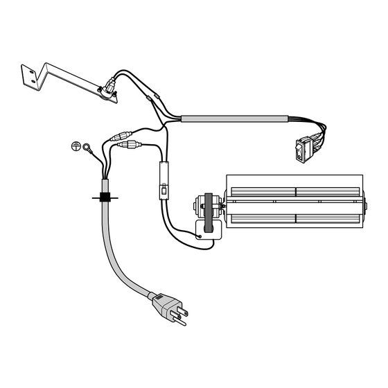
- Page 4 PREPARATION Tools Required • Phillips Screwdriver • Wire Cutter This blower contains assembly instructions for ED series. For the CRHQD250T, CRHSD25RT, BD23 series, Q stove, PCSD25RT series and FBD400 series see page 8 - 13. BLOWER INSTALLATION ED SERIES Protection Tab Install Power Cord and Grounding...
- Page 5 INSTALLATION - ED SERIES 4. Attach the grounding terminal to top cover WARNING: Before installing with 1) M4.2X8 screw (AA). Refer to wiring the blower, be certain to turn off diagram, page 15. Be sure to insert the gasket between the protection tab and the unit, and allow time for unit the grounding terminal (see Figure 4).
- Page 6 INSTALLATION - ED SERIES 6. Insert the female port, which is on the 9. Attach temperature sensor to the back of white power supply wire (marked with P1), the firebox with 2) M4.2X8 screws (AA) into the corresponding male port (marked (see Figure 9).
- Page 7 INSTALLATION - ED SERIES 12. Remove 2 screws securing grill to stove 16. Connect the AUTO, OFF, MAN wires to front. Carefully set grill aside (see Fig- the three corresponding male tabs on the ure 12). rocker switch (see Figure 15). AUTO OFF (O) Rocker Switch...
-
Page 8: Installation
INSTALLATION CRHQD250T and Q Series Install Wiring and Install Blower Install Temperature Grounding Terminal Sensor Install Rocker Switch BD23 Series PCSD25RT and CRHSD25RT Install Temperature Sensor Install Install Wiring and Blower Grounding Terminal Install Rocker Switch Install Rocker Switch FBD400 Series Install Temperature Install Blower Sensor... - Page 9 INSTALLATION - CRHQD250T, Q SERIES, B23 SERIES, PCSD25RT, CRHSD25RT AND FBD400 SERIES 4. Attach the temperature sensor to the back WARNING: Before installing of the firebox with 2) M4.2X8 screws (AA) the blower, be certain to turn off (see Figure 21). the unit, and allow time for unit to cool down.
- Page 10 INSTALLATION - CRHQD250T, Q SERIES, B23 SERIES, PCSD25RT, CRHSD25RT AND FBD400 SERIES 6. Connect two black and yellow wires (fe- 9. Insert the blower connector (male port) male ports) marked T1 and T2 with the into the female port on the wire connector. two male ports on the temperature sensor This protects the jacket in the fireplace (see Figure 23).
- Page 11 INSTALLATION - CRHQD250T, Q SERIES, B23 SERIES, PCSD25RT, CRHSD25RT AND FBD400 SERIES 12. Bundle the wiring with the cable tie (see 13. CRHQD250T and Q Series Remove 2 Figure 29). Attach cable tie to the stove screws securing grill to stove front. Care- through the hole as shown in Figure 29.
- Page 12 INSTALLATION - CRHQD250T, Q SERIES, B23 SERIES, PCSD25RT, CRHSD25RT AND FBD400 SERIES 15. CRHQD250T, Q Series and BD32 Series 16. BD23 Series Remove screws securing Remove screws securing front log bracket control panel door (see Figure 32). and control panel (see Figure 31a). CRHSD25RT and PCSD25RT Remove screws securing control panel (see Figure 31b).
-
Page 13: Electrical Connection
INSTALLATION - CRHQD250T, Q SERIES, B23 SERIES, PCSD25RT, CRHSD25RT AND FBD400 SERIES 19. Push the rocker switch into the control 20. Reattach the control panel and log bracket panel (see Figure 35). (if applicable) with screws removed in step 15 (see Figure 31, page 12). 21. -
Page 14: Grounding Instructions
GROUNDING INSTRUCTIONS This heater is for use on 120 volts. The cord has a plug as shown at A. An adapter as shown at C is available for connecting three-blade grounding-type plugs to two-slot receptacles. The green grounding lug ex- Cover of tending from the adapter must be connected Grounded... -
Page 15: Electrical Wiring Diagram
ELECTRICAL WIRING DIAGRAM Any electrical re-wiring of this appliance must WARNING: If repairing or be done by a qualified electrician. This wiring must be done in accordance with local codes replacing any electrical compo- and/or in Canada with the current CSA C22.1 nent or wiring, the original wire Canadian Electrical Code, and for US instal- routing, color coding and secur-... -
Page 16: Warranty
We make no other warranty, expressed or implied. LIMITED WARRANTY ProCom Heating, Inc. warrants this product to be free from defects in materials and components for ONE (1) year from the date of first purchase, provided that the product has been properly installed by a qualified installer in accordance with all local codes and instructions furnished with the unit, operated and main- tained in accordance with all applicable instructions.
Need help?
Do you have a question about the QEB100 and is the answer not in the manual?
Questions and answers