
Related Manuals for Racal Acoustics RA711/1011

Summary of Contents for Racal Acoustics RA711/1011
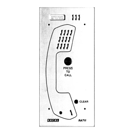
- Page 1 USER GUIDE RA711/1011, /1012 /1013 & Vandal Resist Telephones • • PRESS CALL EMERGENCY • INFORMATION AC AL AC O U STICS December I 992 Publication No: 552625 lss. 2...
- Page 2 Contents...
- Page 3 General The types of telephones covered by this guide are approved in the United Kingdom under the no. S/3064/3/N/502517 for connection to a direct exchange line (i.e. a line e}{clusive to the meter qnd not 'spared'), to an extensioq of a dires .: t exchange line or to �n ext�i}§ion on certain typ��...
-
Page 4: Approved Facilities
Approved Facilities This apparatus has been approved for use of the following facilities:- Loudspeaking n condition (Jin Audible and visual alarm indication of incom1 Installation access using special tools only. External mains to D.C. power supply volts) supplied with each instrument, Part No. - Page 5 Approved Facilities en connected to most compatible PBXs, e. However it cannot be guaranteed that conditions of connection. Any cases of instance to your local supplier of the instrument. . 3.
-
Page 6: Operation
Operation -RA711/1011 a a 8-->- Ext. No. x 143 Alarm (behind panel) - 4 -... - Page 7 RA711/1012 RA711/1013 Operation & Ext. No. Alarm (behind panel) OPOLICE OFIRE OAMBULANCE - 5 -...
-
Page 8: Installation
Installation The following information is provided for use by your approved network supplier only. The 711 tel e can be either wall m mounted. Wall mounting can be sur , flush or inset into the options are available, as defined the "Electrical Connections Make sure that these are set correct! re finally fitting the unit... - Page 9 Installation Wall Inset Installation Produce hole in wall 310mm high by 145mm wide by 60mm deep. Use size 0 screws with rawlplugs ( 4 oft) to fix back box int6 wall, with cut-out at the bottom. Connect the cabling, as detailed under "Electrical Connections", and then to the back box (as described under Wall Flush Installation, item 3).
- Page 10 Installation the top-of-pole mounting top of the pole. Tighten the grubscrews to secure mounting. Fix the surface mounting back box to the top-of-pole mounting with the · screws provided. Connect the cabling, as detailed under "Electrical Connections", and then fit to the back box (as described Wall Flush Installation, Electrical Connections...
- Page 11 Installation Line Terminal Connections and Selections The number of telephones which can be connected to a direct exchange line or is limited by the ringer eql]ivalence nu111per (REN) of.all the telephOnes value of this telephone is I. In case of doubt consult your telephone supplier. The Terminal block mounted at the back of the unit is labelled as follows: - bell pltig...
- Page 12 Installation Programming of Autodial Keys Ensure the 9volt power supply is connected and switched on. PANEL.KEYS. To store telephone n 'behind' the'Aut ess P §! Tticular Autodial key to be programmed, the group which include the 'STORE' and 'PAU hat' PRESS 'S 1' to the top (EMERGENCY or...
Need help?
Do you have a question about the RA711/1011 and is the answer not in the manual?
Questions and answers