Table of Contents
Advertisement
Quick Links
User Manual
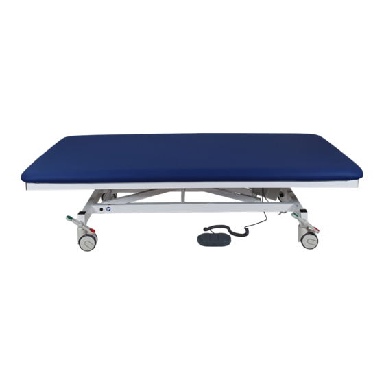
2800XL and 4000E / 4800E series model
Dear customer,
Congratulations on purchasing a product of outstanding quality.
Use of the best materials from renowned suppliers guarantees years of trouble-free operation, provided the
device is handled correctly and as intended in accordance with the conditions described in the user manual.
In the unlikely event you need to make a claim, please contact us.
We welcome suggestions from the users of our products.
Contents
1.
Safety information.................................................................................................................................... 2
1.1
Applied symbols .............................................................................................................................. 2
1.2
Applied standards ............................................................................................................................ 2
1.3
Safety information ............................................................................................................................ 2
1.4
Intended purpose ............................................................................................................................. 3
1.5
Information on setup and use .......................................................................................................... 3
1.6
Commissioning ................................................................................................................................ 3
1.7
Safety notices .................................................................................................................................. 3
1.8
Entrance area .................................................................................................................................. 4
1.9
Model designation and type labelling .............................................................................................. 5
1.10
Meaning of the serial number .......................................................................................................... 5
2.
Operating manual .................................................................................................................................... 6
2.1
Table design .................................................................................................................................... 6
2.2
Height adjustment ............................................................................................................................ 6
2.3
Head part adjustment ...................................................................................................................... 6
2.4
Adjustment of other sections ........................................................................................................... 7
2.5
Movability (model dependent or optional) ....................................................................................... 8
2.6
Additional equipment ....................................................................................................................... 9
3.
Additional accessories (for user-specific table configuration), in extracts............................................. 10
4.
Technical data ....................................................................................................................................... 11
4.1
Individual models ........................................................................................................................... 11
4.2
Technical data for electric motor ................................................................................................... 13
4.3
Technical data for hydraulic system .............................................................................................. 14
5.
Cleaning instructions ............................................................................................................................. 14
6.
Maintenance and technical inspection .................................................................................................. 15
7.
Safety devices ....................................................................................................................................... 16
8.
Reporting obligation............................................................................................................................... 16
9.
Disposal ................................................................................................................................................. 17
10. Declaration of Conformity ..................................................................................................................... 18
K.H. DEWERT GmbH
Vollmestr. 7
33649 Bielefeld
Germany
Tel. +49 / 521 400 27-0
Fax +49 / 521 400 27-27
info@khdewert.de
www.khdewert.de
Subject to changes in materials and construction as a result of technical progress.
Dewert User Manual 2800XL and 4000E Series - Updated 03.2023/4 MDR
Page 1 of 18
Advertisement
Table of Contents

Related Manuals for K.H. DEWERT 2800XL Series


Summary of Contents for K.H. DEWERT 2800XL Series
-
Page 1: Table Of Contents
Maintenance and technical inspection ....................15 Safety devices ............................16 Reporting obligation..........................16 Disposal ..............................17 10. Declaration of Conformity ........................18 K.H. DEWERT GmbH Vollmestr. 7 33649 Bielefeld Germany Tel. +49 / 521 400 27-0 Fax +49 / 521 400 27-27 info@khdewert.de... -
Page 2: Safety Information
This product is not approved for the American market. Distribution and use of the product in these markets, including through third parties, is prohibited by the manufacturer. 1. Safety information 1.1 Applied symbols Safety instructions and key sections in this user manual are marked with the exclamation mark symbol on the left. -
Page 3: Intended Purpose
Keep a sufficient safety distance to the device during all adjustment procedures. Special attention must be paid to the arms, hands, legs and feet of the user and the patient - RISK OF CRUSHING! Make sure that there are no objects located directly around or above / underneath the device! 1.4 Intended purpose The table is used for the ideal positioning of patients for the purpose of curative and disease treatment, examination, massage and health therapy. -
Page 4: Entrance Area
Prior to and when adjusting the height of the table, make sure that no persons or objects are located in the adjustment range of the table and that nobody has their hands on the underframe The following basically applies: Never reach into or under the frame of the table when adjusting the height. Height adjustment can result in injury if the user does not pay due care and attention. -
Page 5: Model Designation And Type Labelling
head part lying surface foot part head part lying surface foot part head part lying surface foot part Mod. 2850 Mod. 2860 Mod. 2880 lying surface Mod. 2800, 2802, 2804, 4800, 4802, 4804 1.9 Model designation and type labelling The exact model designation depends on the choice of frame colour: -00 white powder coated (RAL 9010);... -
Page 6: Operating Manual
2. Operating manual 2.1 Table design When designing the table frames, special emphasis was placed on functional and operational safety. The number of possible pinching points has thus been minimised, while remaining ones have been covered or protected with spacers to prevent injury, thus ensuring safe and yet simple operation. Nevertheless, necessary caution must always be exercised when using the table. -
Page 7: Adjustment Of Other Sections
lifted slowly to the positive end position. To lower, press down the head part and operate the release lever at the same time. Once the desired position has been reached, let go of the release lever. Head part adjustment using ratchets Head part adjustment is enabled by two metal ratchets. -
Page 8: Movability (Model Dependent Or Optional)
positive end position. To lower, press down the upholstery part and operate the release lever at the same time. Once the desired position has been reached, let go of the release lever. Foot part adjustment (only models 2830XLE, 2830XL/H, 2860XLE, 2860XL/H) The foot part can be adjusted in upwards adjustment (positive direction) or - with roof position - also in downwards adjustment (negative direction). -
Page 9: Additional Equipment
Central movability By operating a lever (on the outside of the table feet), all four castors are activated simultaneously. The following moving options exist: Stage 1: The castors of the table are locked and can neither be moved nor rotated. Stage 2: = centre position: The castors are released and can be moved and rotated, the table can be moved in all directions. -
Page 10: Additional Accessories (For User-Specific Table Configuration), In Extracts
Push handles (model dependent optional equipment) Depending on the actual equipment, push handles are located either at the end of the head part or the foot part, or on both sides. When moving the table, always use both hands on the push handles to push/pull the table. Foldable side guard (model dependent optional equipment) Folding down the side guard: Grasp the side guard with one hand in the middle of the guard frame at the top (or with two hands on the left and right at the top). -
Page 11: Technical Data
4. Technical data 4.1 Individual models Models 2800XLE 2800XL/H 2805XLE 2805XL/H 2802XLE 2802XL/H 2804XLE 2804XL/H Max. length (mm) 1950 1950 1950 1950 Width (mm) 1000; 1100; 1000; 1100; 1200 1200 Min. – max. height (mm) 480 - 920 500 - 920 480 - 920 500 - 920 Adjustment time (motor) (s) - Page 12 Models 2808XLE 2808XL/H 2810XL/H 2815XLE Max. length (mm) 2190/1790** 2190/1790** 2000 1950 Width (mm) Min. – max. height (mm) 520 - 960 540 - 960 550 - 970 510 - 950 Adjustment time (motor) (s) Adjustment time, inclined position (motor) (s) Manual Weight (approx., depending on equipment) kg Head part adjustment range...
-
Page 13: Technical Data For Electric Motor
Models 2860XL/H 2880XLE 2880XL/H 2910XLE Max. length (mm) 1950 1950 1950 2000 Width (mm) Min. – max. height (mm) 530 - 950 510 - 950 530 - 950 540 - 980 Adjustment time (motor) (s) Adjustment time, inclined position (motor) (s) Weight (approx., depending on equipment) kg Head part adjustment range +45°... -
Page 14: Technical Data For Hydraulic System
Mode of operation: Electromechanical linear motor with maintenance-free lifetime lubrication Intermittent duty – installed thermal switch Electronic activation with internal supply for the control element Duty cycle (DC): 25 s / 400 s i.e. move the table for max. 25 seconds under nominal load, then observe a break of at least 400 seconds. -
Page 15: Maintenance And Technical Inspection
Do not use aggressive, abrasive or corrosive agents. Heavily soiled chrome-plated parts can be cleaned with a chrome polish (e.g. Sidol). After cleaning, dry the frame with a soft dry cloth. Seal deep scratches and worn areas with suitable repair agents to prevent moisture penetration. Important: At tables with hydraulic height adjustment as well as for the gas springs, wipe the piston rod with a soft cloth at regular intervals. -
Page 16: Safety Devices
result in hazards for patients and users. In the event of uncoordinated modifications to the table, the Declaration of Conformity loses its validity and the warranty shall become null and void. We cannot be held liable for damages resulting from uncoordinated modifications. Only original Dewert spare parts may be used. -
Page 17: Disposal
A serious incident is an incident that directly or indirectly had, could have had, or may have had any of the following consequences: • death of a patient, user or other person, • temporary or permanent serious deterioration of the state of health of a patient, user or other person, •... -
Page 18: Declaration Of Conformity
10. Declaration of Conformity EU Declaration of Conformity for medical devices Manufacturer: K.H. DEWERT GmbH Vollmestr. 7 D-33649 Bielefeld SRN. DE-MF-000005967 Product: Height adjustable table Model 2800XLE, 2802XLE, 2804XLE, 2800XL/H, 2802XL/H, 2804XL/H, designation*: 2805XLE, 2806XLE, 2807XLE, 2805XL/H, 2806XL/H, 2807XL/H, 2808XLE, 2815XLE, 2820XLE,... - Page 19 Checklist for maintenance/technical inspection to IEC 62353 and DGUV Regulation 3 Device Model designation Manufacturer K.H. Dewert GmbH Serial no. Location Responsible person Date, inspector Actuator designation Inspections FAIL Description of defects Visual inspection Overall impression of the table OK? Labels, CE mark, type plate present? Manufacturer’s operating manual available and accessible?
- Page 20 FAIL Description of defects Height retained? Hydraulic pump leaking? Smooth lowering possible? Check by operating the pedals to lower the table Strong noise development? Wipe the piston rod with a cloth Lying surface adjustment functions: Metal ratchets - arrester - gas spring Metal ratchet inspection: Lifting the lying surface segment: Do the two metal ratchets engage properly and securely? Do they engage evenly?
Need help?
Do you have a question about the 2800XL Series and is the answer not in the manual?
Questions and answers