Advertisement
Quick Links
NOTE:
Please read all instructions
carefully before using this
product
Table of Contents
Safety Notice
Hardware Pack
Assembly Instruction
Parts List
Warranty
Ordering Parts
Model
BF-1200
Retain This
Manual for
Reference
07-20-09
OWNER'S
MANUAL
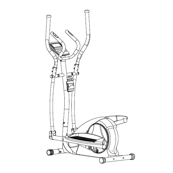
Deluxe Elliptical Machine
14777 DON JULIAN RD., CITY OF INDUSTRY, CA 91746
Tel: (800) 999-8899 Fax: (626) 961-9966
www.impex-fitness.com
info@impex-fitness.com
BF-1200
®
IMPEX
INC.
Advertisement

Summary of Contents for Sports Authority BODYFIT BF-1200
- Page 1 NOTE: Please read all instructions carefully before using this product Table of Contents Deluxe Elliptical Machine Safety Notice BF-1200 Hardware Pack Assembly Instruction Parts List Warranty Ordering Parts Model BF-1200 Retain This Manual for Reference 07-20-09 OWNER'S MANUAL ® IMPEX INC.
-
Page 2: Table Of Contents
TABLE OF CONTENTS BEFORE YOU BEGIN...................…. IMPORTANT SAFETY NOTICES..............…. HARDWARE PACK………..…..............…. ASSEMBLY INSTRUCTIONS................…. EXPLODED DIAGRAM………………………………………………………………. PARTS LIST....................… WARRANTY....................…. ORDERING PARTS..................….. BEFORE YOU BEGIN ® Thank you for selecting the BODY FIT Deluxe Elliptical Machine BF-1200 by IMPEX INC. For your safety and benefit, read this manual carefully before using the machine. As a manufacturer, we are committed to provide you complete customer satisfaction. -
Page 3: Important Safety Notices
IMPORTANT SAFETY NOTICE PRECAUTIONS This exercise machine is built for optimum safety. However, certain precautions apply whenever you operate a piece of exercise equipment. Be sure to read the entire manual before you assemble or operate your machine. In particular, note the following safety precautions: 1. - Page 4 WARNING LABEL PLACEMENT The Warning Label shown here has been placed on the Rear Stabilizer. If the label is missing or illegible, please call customer service at 1-800-999-8899 for replacement. Apply the label in location shown.
-
Page 5: Hardware Pack
HARDWARE PACK NOTE: The following parts are not drawn to scale. Please use your own ruler to measure the size. -
Page 6: Assembly Instructions
ASSEMBLY INSTRUCTION NOTE: It is strongly recommended that two or more people assemble this machine to avoid possible injury. STEP 1 (See Diagram1) A.) Do not tighten the Nuts and Bolts until instructed to do so. B.) Attach the Front Stabilizer (#39) to the Main Frame (#32). Secure it with two M8 x 2 ½” Carriage Bolts (#35), two ∅... - Page 7 STEP 2 (See Diagram 2) A.) Note: Extra help may be needed to hold the Front Post (#42) while connecting the computer wires. B.) Connect the Upper Computer Wire (#91) from the bottom of Front Post to the Lower Computer Wire (#92) from the main Fame (#32).
- Page 8 STEP 3 (See Diagram 3) A.) Note: In order to install the Pedal Supports (#30 & #38), extra help may be needed. B.) Do not tighten Nuts and Bolts until instructed to do so. C.) Attach the Left Pedal Support (#38) onto the groove on left Roller Wheel (#49). D.) Insert the pivot on Left Pedal Support into the hole on the left Connecting Bracket (#54).
- Page 9 STEP 4 (See Diagram 4) A.) Cover the heads of the two M8 x ¾” Hex Bolts (#6) pre-installed by factory with two M8 Nut Caps (#5). B.) Cover the two M8 Aircraft Nuts (#23) installed in Step-3 with two M8 Nut Caps (#5). DIAGRAM 4...
- Page 10 STEP 5 (See Diagram 5) A.) Attach the two Pedals (#29) onto the Left & Right Pedal Support (#38 & #30). Secure each Pedal with three M8 x 1” Allen Bolts (#28). DIAGRAM 5...
- Page 11 STEP 6 (see Diagram 6) A.) Insert the Right Stride Handle (#2) into the Right Connecting Rod (#15). Insert the Left Stride Handle (#44) into the Right Connecting Rod (#41). B.) Securely tighten each Handle with two M8 x 2” Carriage Bolts (#11), two Ø 5/8” Curved Washers (#24), two Ø...
- Page 12 STEP 7 (See Diagram 7) A.) Attach the Water Bottle Rack (#18) to the Front Post (#42). Secure it with two M5 x 5/8” Philips Screws (#17). B.) Store the Water Bottle (#14) in the Rack. DIAGRAM 7...
- Page 13 STEP 8 (See Diagram 8) A.) Attach the Stationary Handle (#27) to Front Post (#42). Secure it with four M8 x ¾” Allen Bolts (#21), four Ø 5/8” Lock Washers (#7), and four Ø 5/8” Flat Washers (#22). DIAGRAM 8...
- Page 14 STEP 9 (See Diagram 9) A.) Remove the four M5 x 5/8” Computer Philips Screws (#43) from the Computer (#45). B.) Connect the Upper Computer Wire (#91) to the wire on Computer. C.) Plug the sensor wire (#93) on the Front Post (#42) into the Computer. D.) Attach the Computer to the bracket on Front Post.
- Page 15 STEP 10 (See Diagram 10) A.) Plug the AC Adapter (#34) to110v outlet, and plug the power cord into the Main Frame (#32). Note: Only use the original AC Adapter from manufacturer. Do not use any Adapter which is not from manufacturer. DIAGRAM 10...
-
Page 16: Exploded Diagram
EXPLDOED DIAGRAM... -
Page 18: Parts List
PARTS LIST KEY NO. DESCRIPTION Q’ty Stride Handle Cover Cap Ø 1 1/8” x Ø 7/8” Spacer Right Stride Handle Ø 1 1/8” x ½” Bushing Ø 1 ½” Stride Handle Bushing Ø 1 1/8” x ¼” Spacer Stationary Handle Grip Connecting Bracket M8 Nut Cap Ø... -
Page 19: Warranty
® IMPEX INC. LIMITED WARRANTY ® IMPEX Inc. ("IMPEX ") warrants this product to be free from defects in workmanship and material, under normal use and service conditions, for a period of two years on the Frame from the date of purchase. This warranty extends only to the original purchaser.
Need help?
Do you have a question about the BODYFIT BF-1200 and is the answer not in the manual?
Questions and answers