
Related Manuals for Trademaster TM26005


Summary of Contents for Trademaster TM26005
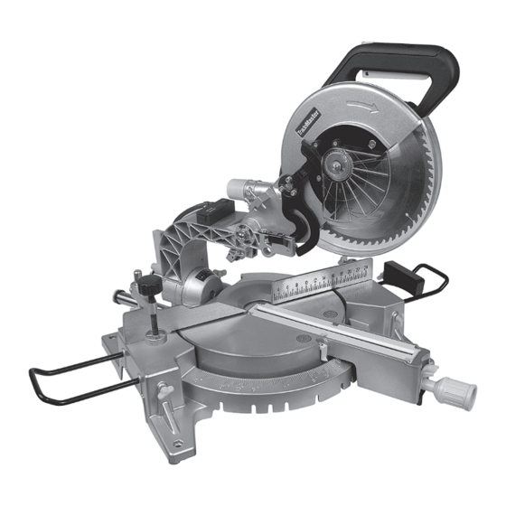
- Page 1 Operator’s Manual for 10" Sliding Compound Mitre Saw TM26005 Model No. UPC 7-72142-26005-4 Trademaster Parts & Service 205 Frobisher Drive Waterloo, ON N2V 2G4 tel: 866-332-3307 fax: 866-332-3308...
-
Page 2: General Safety Instructions
GENERAL SAFETY INSTRUCTIONS WARNING! Read and understand all instructions. Failure to follow all instructions listed below may result in electrical shock, fire and/or serious personal injury. SAVE THESE INSTRUCTIONS Work Area • Use common sense, stay alert and watch what you are doing while operating a power tool. -
Page 3: Additional Safety Instructions For Mitre Saws
• Always disconnect the power cord from the • Clear chips and small blocks on the base to ensure a electrical outlet before storing the tool, making smooth, clean surface. adjustments or adding/replacing accessories. This • Before cutting any work pieces, make sure that the simple prevention will reduce the risk of accidental nails and screws around the cutting position have starting of the tool. -
Page 4: Extension Cords
Extension Cords: Using the Laser collimator system Make sure your extension cord is not damaged. When WARNING: Do not stare directly at the laser beam. using an extension cord, be sure to use one heavy Never aim the beam at any person or an object other enough to carry the current your product draws. -
Page 5: Technical Specifications
Technical Specifications ITEM DESCRIPTION Motor No-Load Speed:4600RPM Power Supply 120V/60Hz/Single Phase/15 Amps Arbor Diameter 0.625” (5/8") Blade Diameter 10” Cutting Capacity Cross cut 90°: 11.81” x 2.95” (300mm x 75mm) Bevel cut 45° x 90°: 8.26” x 2.95” (210mm x 75mm) Compound cut 45°... -
Page 6: Blade Guard
When installing the new saw blade check that the teeth point in the direction of the arrow (See the protective Protective Arrow Saw Blade cover). Cover Arrow Outer Flange Inner Flange Install Shaft Hex Bolt Saw Blade Install the outer flange and the hex bolt. Then, press down on the shaft locking arm, and tighten the hex bolt firmly by turning it counter clockwise using the socket wrench. -
Page 7: Operating The Switch
Operating the Switch Protective Button To prevent accidental starting, the tool is equipped with a protective switch. To start the tool, you should first press Trigger Switch the protective switch and then press down the trigger switch. The tool shuts off when you release the trigger switch. -
Page 8: Operation
Operation Knob Press Cut (cutting a small work piece) The work piece size within the scope of 70mm(H) x 210mm(W) can be cut in the following way: Push the carriage to the end towards the cross bar, tighten the knob to fix the carriage. Then use the vice to secure the work piece. - Page 9 Setting a Bevelling Angle Only when the auxiliary stopper is fixed on the left side, as shown on the drawing, can the saw blade be bevelled to a 45° angle. To adjust the bevelling angle, loosen the fixed handle, then incline the saw blade to the left until the indicator reaches the desired angle on the mitre square.
-
Page 11: Parts List
Parts List Item Description Qty. Item Description Qty. Item Description Qty. Rubber Bracket Stator Assembly Screw Nylon Nut M8 Cross Screw M5×70 Sliding Bar Ring Long Handle M6×70 Wind Resist Ring Screw M4X10 Base Rotor Needle Plastic Fence Handle Cap Nut M10 Short Handle M6×20 Blade Lock Flat Washer D10... - Page 12 LIMITED WARRANTY TradeMaster Parts & Service (TMPS) warrants to the original purchaser only that its TradeMaster brand power tools will be free from defects in material or workmanship for a period of three years from the date of purchase. In the event this power tool fails, return the complete tool, transportation prepaid, to your nearest Authorized Service Centre.
- Page 13 Blade change for TM26005 Loosen this screw to release the guard fixed plate Push the entire plastic guard assembly forward. You will see the slot in the front of the fixed plate that the front screw pivots on. When pushing the guard forward, notice the gear...
Need help?
Do you have a question about the TM26005 and is the answer not in the manual?
Questions and answers
Where can I get the power pack to the laser and is this part available?