Table of Contents
Advertisement
Quick Links
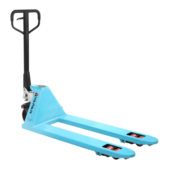
Operator's Manual
Models: YPT25 & YPT30
2,5 and 3 Tonnes Capacity
Pallet Trucks
Design in accordance with EN ISO 3691-5 Standard
Warning!
READ THIS OPERATORS MANUAL BEFORE USING THE PALLET TRUCK
ALWAYS operate, inspect and maintain the pallet truck in accordance with this manual.
Failure to do so may result in property damage or personal injury.
This manual contains important safety, assembly, operation and maintenance information.
Keep for future reference for the life of the product.
Advertisement
Table of Contents

Summary of Contents for YAPAR YPT25
- Page 1 Operator’s Manual Models: YPT25 & YPT30 2,5 and 3 Tonnes Capacity Pallet Trucks Design in accordance with EN ISO 3691-5 Standard Warning! READ THIS OPERATORS MANUAL BEFORE USING THE PALLET TRUCK ALWAYS operate, inspect and maintain the pallet truck in accordance with this manual.
-
Page 2: Table Of Contents
Table of Contents: i. Notes ……………………………………………………………………..…………... 1 . Application Range ………………………………………………………..…………. 2 . Main Features and Specifications …………………………………………………. 3 . Assembling and Disassembling of the Handle …………………………………... 4 . Testing Process and Operating The Pallet Truck ………………………………... 5 . Inspection Before Use …………………………………….……………………….. 6 . -
Page 3: Main Features And Specifications
2. Main Features and Specifications Models YPT25 / YPT30 Capacity (Kg) 2500 / 3000 Maximum Lift Height (mm) Lowered Fork Height (mm) Height Withoud Handle (mm) 431,5/421,5 Fork Length (mm) 1150 Fork Width (mm) Ø 200/180 Steer Wheel Diameter (mm) Ø... -
Page 4: Inspection Before Use
4.2. Use the screw (item 9) in Figure 4 to adjust the pallet truck. After lifting the pallet truck body, turn the screw a little counter-clockwise when it drops. Then repeat this process until the body of the pallet truck lifts normally. The outer hex nut (item 8) on the screw performs the locking function of the pallet truck. -
Page 5: Loading Way And Capacity
• The handle should be left in the up position to eliminate tripping hazards. Figure 6 7. Loading Way and Capacity The ideal loading mode is to place the center of gravity of the load at the central position of the forks. Do not place the load at the tip of the forks. -
Page 6: Troubleshooting Guide
9.4 Adding hydraulic oil to the pump reservoir: a) Ensure forks are in lowered position. b) Lay pallet truck on either side carefully. Position drain plug of hydraulic cylinder up. c) Remove drain plug. d) Add necessery amount of hydraulic oil. e) Close and tighten the drain plug. -
Page 7: Maintenance And Repair
11. Maintenance and Repair • The forks should be unloaded and lowered in the lowest position when the pallet truck is out of work. • Routine checks should be done daily and to be dealt with unusual cases immediately. Please do not use a defective pallet truck to prolong its service life. -
Page 8: Safety Warnings
14.Safety Warnings 14.1 Please read and understand the operation and safety manual before operating this pallet truck. 14.2 Check all parts of the pallet truck before use. Make sure that the wheels, handle bar, forks and lower-lift control lever work properly. 14.3 Wear safety shoes with steel toe caps and gloves when operating the pallet truck.Use goggles during maintenance. -
Page 9: Declaration Of Conformity
PALLET TRUCK Product Type PEDESTRIAN-PROPELLED PALLET TRUCKS Models YPT25, YPT30 and all 2,5 and 3 tonnes capacity Pallet Trucks Name and address of the person authorised to compile the technical construction file Selami Ortaköy Cebeci Cad. No: 115 Küçükköy 34250 Gaziosmanpaşa / İstanbul-TÜRKİYE... - Page 10 Figure 7. Handle Bar Assembly Drawing...
- Page 11 Table 1. Handle Bar Assembly Parts List (Figure 7) Drawing Name Drawing No Code Description YPT25-H-01 Handle Bar YPT25-H-02 Spring plate YPT25-H-03 YPT25-H-04 YPT25-H-05 YPT25-H-06 Bush YPT25-H-07 Pinch Roller YPT25-H-08 Shaft YPT25-H-09 Bush YPT25-H-10 Torsional Spring Handle assembly YPT25-H-11 Control Handle...
- Page 12 Figure 8. General Assembly Drawing...
- Page 13 Table 2. General Assembly Parts List (Figure 8) Drawing Name Drawing No Code Description YPT25-01 Front Guide Roller YPT25-02 Bolt YPT25-03 YPT25-04 Load Roller (Red) YPTW25-04 Load Roller (White) YPT25-05 Bearing YPT25-06 Bolt YPT25-07 Shaft YPT25-08 Roller Side Plate YPT25-09...
- Page 14 Figure 9. Pump Assembly Drawing...
- Page 15 Table 3. Pump Assembly Parts List (Figure 9) Drawing Name Drawing No Code Description YPT25-P-01 Plunger Piston YPT25-P-02 Dust Ring YPT25-P-03 O-ring YPT25-P-04 Guide sleeve YPT25-P-05 O-ring YPT25-P-06 Dust ring YPT25-P-07 Combination ring YPT25-P-08 Sealing screw YPT25-P-09 Locking bar YPT25-P-10...
- Page 16 Table 4. Spare Part List (Figure 8) Drawing Name Drawing No Code Description YPT25-01 Front Guide Roller YPT25-04 Load Roller (Red) YPTW25-04 Load Roller (White) YPT25-08 Roller Side Plate YPT25-09 Extending Roller YPT25-17 Axle General Assembly YPT25-19 Axle Joint YPT25-27...
Need help?
Do you have a question about the YPT25 and is the answer not in the manual?
Questions and answers