Table of Contents
Advertisement
Quick Links
Advertisement
Table of Contents

Summary of Contents for KEISOKU GIKEN LOAD EDGE Series
- Page 1 H i g h P e r f o r m a n c e E l e c t r o n i c L o a d...
- Page 2 Load Station Series Quality Assurance Provision This product passed our close product inspection. When it did not satisfy an early purpose, specifications by trouble after the delivery in a year, we repair it gratis in the case of the responsibility in our production. Please report to agency or us. We repair it in our factory. About measurement precision, I guarantee it for six months after the delivery.
-
Page 3: For Safety Operation
Load Edge Series For safety operation This is an instruction for safety operation. Please read the manual and follow all safety notes. Please understand that we are not responsible for any accidents caused by wrong operation or usage not following the safety note or cautions. - Page 4 Load Edge Series input power Use at rated voltage only. (Input rating : AC 100 V~240 V 50/60 Hz ) In addition, use the power supply cable attached to this product. (attached cable rating : AC 125 V) When used abroad, use a power cable suitable for the shape and rating for the power supply.
- Page 5 Load Edge Series Transportation Turn off all power switches and remove all wirings before moving. Always move the product with the instruction manual. original packing materials when moving transportation. Use equivalent packing materials if original packing materials are not available.
-
Page 6: Safety Symbols
Load Edge Series Safety symbols For safety operation, the following symbols are used in this manual. Read and understand the meanings of each symbol for safety operation. This symbol means Warning, Danger or Notice. Refer to this manual of appropriate page when such symbol was found on the product. -
Page 7: Preface
Load Edge Series Preface General Applicable models. ELZ-175 30V-67.5A-175W Framework of this manual This manual consists of the following chapters. Ch. 1: Product outline Outline and features of this product are presented. Ch. 2: Connections Connections and their cautions are presented. -
Page 8: Check When You Unpack
Load Edge Series Check when you unpack After you unpack, please check if the product suffers any damages and all the accessories are duly provided. Should you find any damages and missing accessories, please contact dealer you purchased from or KG directly. -
Page 9: Cautions When You Transfer
Load Edge Series Cautions when you transfer When you carry this product, grasp the handle on the top surface shown below. C A U T I O N ・ Powers OFF this product before you carry this product. You must hold this handle when carrying it. -
Page 10: Table Of Contents
Load Edge Series TABLE OF CONTENTS For safety operation ........................... 3 Safety symbols ........................... 6 Preface ............................... 7 General ............................7 Framework of this manual ......................7 Check when you unpack ......................... 8 Cautions when you transfer ......................9 TABLE OF CONTENTS ........................10 Chapter 1 Product Outline ...................... - Page 11 Load Edge Series 4.4 I/O setting ..........................38 4.5 Memory function ........................39 4.6 BIAS Unit..........................40 4.7 Current Monitor Range ......................42 Chapter 5 Operations for Load modes ....................43 5.1 Select Load mode........................44 5.2 Load setting .........................45 5.3 Response Rate ........................47 5.4 Current limit setting ......................48 5.5 CC mode ..........................49...
- Page 12 Load Edge Series Chapter 8 Remote control ....................... 81 8.1 GP-IB interface ........................81 8.2 Meas. commands ........................82 8.3 Load setting commands ....................... 83 8.4 System command ......................... 84 8.5 Multi line message ....................... 84 8.6 Status registers ........................84 8.7 GPIB sample program ......................
- Page 13 Load Edge Series 10.3 Load section........................118 10.4 Output section ........................119 10.5 Outline view ........................120 10.6 Operating area ......................... 121 Chapter 11 Maintenance ......................... 122 11.1 Cleaning ........................... 122 11.2 Fuse ..........................122 11.3 Input power cable ......................124 11.4 Calibration ........................
-
Page 14: Chapter 1 Product Outline
This product, ELZ-175, is a high-performance electronic load that can work in lower voltage range and with fast load response due to internal new load circuits that KEISOKU GIKEN developed. In addition, KEISOKU GIKEN‟s new “Extreme Power” technique employed in this electronic load expands its applications because the “Extreme Power ”technology allows peak load power operations that exceeds rated in short-term (*1) -
Page 15: Applications
Load Edge Series 1.3 Applications The following shows examples of the applications with this product. ・ Test for low voltage power supplies for a micro processor. ・ Large current fast pulse load test. ・ Evaluate solar batteries ・ Replace a load switch ・... -
Page 16: Extreme Power Technique(Patent Pending
KEISOKU GIKEN paid attention to this actual procedure of testing and developed the “Extreme Power” technique which allows a consecutive operation with much larger load current than rated as long as the averaged power does not predetermined limit. - Page 17 Load Edge Series Examples When a pulse load of 1KW and 100μs width repeats in period of 500μs, the averaged power will be 1KW × (100μs ÷ 500μs ) = 200W So it is possible to apply this load conditions for up to 20 seconds.
-
Page 18: Chapter 2 Connections
Load Edge Series Chapter 2 Connections Necessary cautions for connections 2.1 Power cable In domestic shipment, we attach a 3-pin AC100V AC cable. Please be careful when you connect power cable because you may get electric shock. W A R N I N G ・... -
Page 19: Cable Connections
Load Edge Series 2.2 Cable Connections T A R G E T D E V I C E ( 2 ) ( 1 ) ( 3 ) Fig. 2-2-1: How to connect cables R E M A R K TARGET DEVICE: e.g. Power supply to be tested, Device under test. - Page 20 Load Edge Series (1) Remote sense cable Be sure to connect remote sensing cables It is necessary to connect remote sensing cables properly when in EXT sensing mode (you can select EXTernal sensing or INTernal sensing by switching a button in rear panel of main unit).
- Page 21 Load Edge Series (2) Load cable As shown in the Fig. 2-2-1, please use hexagon nuts and hexagon head bolts when you connect load cables. Also please use load cables adapted for necessary current capacity and wire the load cables as short as possible. In addition, twist the load cables if the cable length is long and/or if possible.
- Page 22 Load Edge Series (3) External control cable As an external control cable, use a twisted cable when connecting. The wire lines should be selected according to the following requirement. The input signal should be DC signal. In case AC signal is inputted, it is necessary to offset voltage to keep the voltage above 0V any time.
-
Page 23: To Achieve Fast Load Response
Load Edge Series 2.3 To achieve fast load response To achieve fast load response as described in the specification of this product, pay attention to the following: 1. Negative effect by inductance Back electro motive force caused by both inductance of load cable and internal inductance of this product would influence rising time. - Page 24 Load Edge Series 2. Affect by Load current setting As the nature of this product, slew rate may be decreased depending on the slew rate and load current settings. Specifically, if the setting of load current is less than a certain current, the slew rate won‟t exceed the min load response time which is 500ns.
-
Page 25: Current Monitor
Load Edge Series 2.4 CURRENT MONITOR This CURRENT MONITOR can be used when you observe a current waveform by an oscilloscope. ELZ-175 has four ranges of current monitor for accuracy. ・50 50A/5V ・25 25A/5V ・10 10A/5V ・80 80A/5V CURRENT MONITER RANGE R E M A R K ・... - Page 26 Load Edge Series ・Connection to an oscilloscope. When you connect this product to an oscilloscope, please be careful about the polarities of the probes of the oscilloscope to connect as shown in the Fig. 2-4-2. E L L - 3 5 5...
-
Page 27: Trig Out
Load Edge Series 2.5 TRIG OUT TRIG OUT signal can be used when you observe a waveform in dynamic mode operation. R E M A R K ・ The TRIG output is isolated. ・ This output is only valid when in dynamic mode. -
Page 28: Chapter 3 Names And Functions
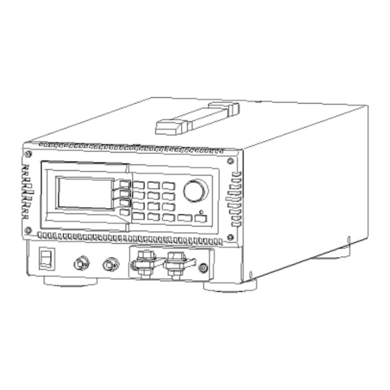
Load Edge Series Chapter 3 Names and Functions Names and functions of parts on the panels and terminal of this product are provided. 3.1 Front panel ( 1 ) ( 2 ) ( 7 ) ( 3 ) ( 4 ) -
Page 29: Display
Load Edge Series 3.1.1 Display ( 1 ) ( 2 ) ( 3 ) ( 4 ) ( 1 1 ) ( 5 ) ( 9 ) ( 1 0 ) ( 6 ) ( 7 ) ( 8 ) Fig. - Page 30 Load Edge Series Icon indicating the scale of increase/decrease load setting by the rotary knob Unless you operate in some specific items, you can use the rotary knob to change load setting. The step value of load change can be selected. This icon shows minimum increment as shown below.
-
Page 31: Rear Panel
Load Edge Series 3.2 Rear Panel ( 9 ) ( 8 ) ( 7 ) ( 6 ) ( 1 ) ( 2 ) ( 3 ) ( 4 ) ( 5 ) Fig. 3-2-1 Rear panel. (1) INPUT connector When option RC-02A (Ripple Noise converter) is built- in, a BNC connector is added there. -
Page 32: Side Panel
Load Edge Series (8) Remote Sensing Terminals The voltage sensing terminals is used for voltage measurement in CR, CV and CP mode. The remote sensing has to be used when set at EXTernal Sensing mode. Contrary to this will cause damage. -
Page 33: Chapter 4 Operations
Load Edge Series Chapter 4 Operations Names and functions of the operation panel, menu selection, memory function, and configuration setting are presented. 4.1 Operation panel MENU ON/OFF Fig. 4-1-1 Operation Panel Function keys These function keys are used to recall function allocated for each menu selected. -
Page 34: Menu Selection
Load Edge Series 4.2 Menu selection There are three (3) menus available in this product. ・LOAD CONTROL you can setup about load. ・MEASURE SETUP you can setup about measurement. ・I/O – MEMORY you can setup GP-IB address and I/O. First of all, it is necessary to select proper menu mode. -
Page 35: Load Control
Load Edge Series 4.3 LOAD CONTROL The LOADS CONTROL consists of the following functions. ・Select maintenance function ・Set slew rate(SR) ・Select Dynamic mode (DYNAMIC) (1)Maintenance function Call LOAD CONTROL menu with referring “4.2 menu selection” When pressed F1 key, it will show menu selection screen (menu page 1). - Page 36 Load Edge Series (2)Current limit setting Press F2 key twice at menu page 1 for current limit setting. Refer to the “5.4 Current limit“ (3)Master –Slave setting Press F3 key for Master-Slave selection mode at menu page-1. Press ENT key after selection.
- Page 37 Load Edge Series (4) Version information Press F2 key at menu page 3 for checking current version of this unit. P u s h " F 2 " k e y Fig. 4-3-5 Menu page 2 Operations 37...
-
Page 38: I/O Setting
Load Edge Series 4.4 I/O setting I/O setting consists of the following settings. ・GP-IB address ・Contrast of the display (LCD) ・Brightness of back light of the display (LCD) (1) GP-IB address First, call the “I/O – MEMORY” by the method as described above “... -
Page 39: Memory Function
Load Edge Series 4.5 Memory function You can save up to six (6) group of setting conditions, and recall any of those conditions freely. Parameters that you can save in this memory function are as follows: ・Currently selected load mode ・Load setting value(s) in each load mode... -
Page 40: Bias Unit
Load Edge Series 4.6 BIAS Unit This is how to turn BIAS Unit on or off 4.6.1. Select LOAD CONTROL in menu page and Push F1 Key four times and Push ENT Key. P u s h F 1 k e y P u s h F... - Page 41 Load Edge Series 4.6.3. After Selecting, If you want to finish this mode, Push MENU Key. 4.6.4. If you turn BIAS Unit on during load ON state, a warning appears. 図 4-6-3 Bias Unit warning 4.6.5. In this case Push MENU Key or CE Key Push MENU Key again and BIAS mode is closed.
-
Page 42: Current Monitor Range
Load Edge Series Current Monitor Range This is how to change current monitor range. 4-7-1 Select LOAD CONTROL page (default) Fig. 4-7-1 How to set current monitor range 1 4-7-2 Push rotary knob four times and LCD shows cm-r. Fig. 4-7-2 How to set current monitor range 2 4-7-3 Turn around rotary knob to right so current range is changed mentioned below. -
Page 43: Chapter 5 Operations For Load Modes
Load Edge Series Chapter 5 Operations for Load modes This product has seven (7) load modes; constant current (CC), constant resistor (CR), constant voltage (CV), constant power (CP), ext. control (EXT), dynamic (DYNAMIC), and short (SHORT) modes. Please check first which mode you will use, and setup it properly. -
Page 44: Select Load Mode
Load Edge Series 5.1 Select Load mode To select a load mode, press the rotary knob once to display “MODE” as shown below. While the “MODE” is displayed, you can select a load mode. P u s h o n c e Fig. -
Page 45: Load Setting
Load Edge Series Then you turn the knob, load modes that can be selected are displayed sequentially and repeatedly. C R M o d e C C M o d e C V M o d e S h o r t M o d e C P M o d e E x t . - Page 46 Load Edge Series Use ten keys to input values and press ENT key to confirm it. Example: setup 28.50A in CC mode Note: you need to select CC mode before you input the value. Use ten keys to input . Then you can find underscored “28.5” is displayed as shown below.
-
Page 47: Response Rate
Load Edge Series 5.3 Response Rate You can change the response speed (slew rate) of both rising and falling time that is effective when load is ON/OFF and load condition changes. The response speed depends on the current range selected then. Load response speed of both rising and falling time is identically setup. -
Page 48: Current Limit Setting
Load Edge Series How to change response speed (1) In Constant Current and External Control modes Make sure if it is in CC mode or Ext. Control mode. In the LOAD CONTROL menu, press F2 key to display a window where you can change the value. -
Page 49: Cc Mode
Load Edge Series 5.5 CC mode In this CC mode, a setup current flows regardless of the load voltage S e t C u r r e n t I n p u t V o l t a g e (1)... -
Page 50: Cr Mode
Load Edge Series 5.6 CR mode In this CR mode, load current changes in proportion to the load voltage as if resistor is used. This mode is adapted to a general load test. L o a d C u r r e n t... -
Page 51: Cv Mode
Load Edge Series 5.7 CV mode In this CV mode, for such power supplies having internal resistor, the load current changes so that the load voltage should be constant. This mode is adapted to test rechargeable batteries. L o a d... -
Page 52: Cv+Climit
Load Edge Series N O T E ・ Due to the principle of CV mode Operation, you may find oscillation and unstable load control because of wiring conditions or DUT. In such cases, you may stabilize the load control by changing the loop gain value to stabilize the measurement. -
Page 53: Cp Mode
Load Edge Series 5.8 CP mode In this mode, load current is determined so that the load power becomes constant. This mode is adapted for simulating switching power supplies that tend to increase the load current as the voltage decreases. -
Page 54: Load Control Changing By A Value Of Voltage
Load Edge Series 5.9 Load Control Changing by a value of voltage You can change load mode by setting a value of voltage. Load mode explanation OFF: This function is off. CR(H): Change CR mode when measured voltage is upper than setting voltage. - Page 55 Load Edge Series (3) Set a changing point of load voltage Push F3 Key and input value of voltage by using ten key and push ENT Key. E N T F i n i s h Fig.5-9-3. How to select mode 3 (4)...
-
Page 56: Ext Mode
Load Edge Series 5.10 EXT mode In this mode, load current becomes proportional to the voltage inputted to the EXT terminal on the rear panel. L o a d C u r r e n t E x t . C o n t r o l V o l t a g e 1 0 V Press the rotary knob to set mode select condition. -
Page 57: Short Mode
Load Edge Series 5.11 SHORT mode In this mode, load terminals are shortened Load current can flow up to the maximum rated Ampere or setup current limit whichever smaller, but the current range is fixed to High range. Press the rotary knob to set mode select condition. And then turn the knob until “ST” is displayed as shown below. -
Page 58: Dynamic Load Mode (Dynamic)
Load Edge Series 5.12 Dynamic Load mode (DYNAMIC) This mode repeats multiple loading conditions. All loading conditions of CC, CV, CP, EXT and SHORT modes can be set. However each loading condition has to be in a same L o a d loading mode. - Page 59 Load Edge Series (2)Load mode Load mode selected is kept effective when you setup dynamic mode. For example, if CC mode is selected, then you select dynamic mode, the CC mode is still effective. But if you change the load mode while dynamic mode is select, the dynamic mode is stopped and the selected mode is selected.
- Page 60 Load Edge Series (5) Setting parameters. The following figures show each parameter and operation. *Set CC1 and CC2 only and skipped other settings. C u r r e n t ( A ) ※ T I M E ( C C 2 ) = 0 . 0 0 m S...
- Page 61 Load Edge Series (6) Execute Start executing after completion of CC1 and CC2 setting. As to start, press F3 at dynamic load change mode and select OFF, LOOP or SINGLE. Press “ENT” key or “Rotary” knob to confirm. (6-1) When in OFF mode...
- Page 62 Load Edge Series (7) Example of setting Ex-1 Continuous operation Condition: 1A for 1ms at CC mode then 2ms for rest (no load). Set art CC mode at the normal setting screen. Set CC1 at dynamic load setting screen. Set CC2 at dynamic load setting screen.
- Page 63 Load Edge Series Ex.-2 Single operation Condition: Draw current of 10A for 10ms at CC mode once. 1) In normal menu, select CC mode. 2) In dynamic load setting menu, setup parameters of CC1 3) Setup parameters of CC2 where parameter of the effective time should be zero (0).
- Page 64 Load Edge Series (9)Store setting, read data, clear [MEM] Change to MEM and setting Press [F2] at dynamic load mode. The [MEM] mode is selected by [UP], [Down] key of rotary encoder or numeric keys. Pressing [F2] or [UP] is same in function wise.
- Page 65 Load Edge Series (9-3) Clear the setting Select [CLEAR] at MEM mode. Clear the setting of dynamic loading mode to the default value. Set the following to all steps: SET=0.0/TIME=0.0/SR=MAX The hardware will be renewed its setting in accordance to the data being read.
-
Page 66: Dynamic (Sequence) Mode Operation
Load Edge Series 5.13 Dynamic (Sequence) mode operation ・ The sequence mode is to test in different loading condition continuously but in fixed duration per step. ・ Maximum 1024 steps loading condition can be set as L o a d... - Page 67 Load Edge Series (2) Setting by sequence control software .xls The sequence mode is supported by GPIB or USB. The attached Excel can be used when in USB interface. It is necessary to install device driver to the PC. As for the installation, refer to “8.8 USB...
- Page 68 Load Edge Series ⑥ Down load Transfer the data to the electronic load. The electronic load shows [SEQLOAD] after completion. Fig. 5-12-3 Display at sequence mode ⑦ start Start the sequence operation ⑧ stop Stop the sequence operation The attached sequence control software .xls is developed by VBA of Excel.
- Page 69 Load Edge Series (3) Notice on sequence mode (a) Setting The operation of sequence mode is depending on the present loading mode and current range. Current range cannot be set from the sequence mode. The sequence load setting is set as the condition of the present loading mode.
- Page 70 Load Edge Series Appendix:1) Setting command 1) Initialize command SQI no argument Function Clear all data to “0” 2) Load setting data SQD [Data index No. (1-1024)],[Slew rate],[Load setting] Function: Set each loading condition 3) Execute condition SQU [No. of loops, 1 – 65535, 0 for continue],[data index no.(1 –...
-
Page 71: Chapter 6 Operations For Meas. Mode
Load Edge Series Chapter 6 Operations for meas. mode This product has three (3) meas. modes: Current, Voltage, and Power. There are 2 ranges for voltage measurement and 3 ranges for current measurement for accurate measurement. For ripple noise measurement, there is an optional RC-02 meas. module (Factory option). -
Page 72: Sampling Rate
Load Edge Series NOISE Noise by RC-02A RIPPLE Ripple by RC-02A Note: RC-02A module can be provided by a factory option of this product. R E M A R K ・When CV mode is selected , connect remote sense cables to the sense terminals. Otherwise this product cannot work properly. - Page 73 Load Edge Series P u s h o n c e P u s h t w i c e Fig. 6-3-1 Voltage range setting - 1 After the knob is pressed first, MODE is displayed in the dot circle in the upper figure.
- Page 74 Load Edge Series figure. When you press the knob three times quickly, “Cr” is displayed. Turn the knob to select “7.5A”, “67.5A”, or “AT” as shown below. “7.5” 7.5A fixed range “67.5” 67.5A fixed range “AT” Auto range Press ENT key or the knob to confirm the setting selected.
-
Page 75: Chapter 7 Alarms
Load Edge Series Chapter 7 Alarms Alarms of this product are explained. In this product, when an alarm occurs, Load is automatically set to OFF, with beep sound rung and error message displayed. 7.1 Over current limit To protect load section, load current of this product can be limited. When you setup the current Limit current will be limited with the 110% (typ.) of setting value. -
Page 76: Over Voltage Alarm
Load Edge Series 7.2 Over voltage alarm When the load volt exceeds the tolerance value, this alarm operates. This protection will be activated when applied 104% (typ) of rated voltage. Model Range HIGH Range LOW ELZ-175 31.2V 4.16V Table 7-2-1 Threshold voltage for OVP. -
Page 77: Overheat Alarm
Load Edge Series 7.3 Overheat alarm When temperatures on the heat detection point on of the load exceeds 95℃(Typ), this alarm is issued. Fig. 7-3-1 Display of overheat alarm C A U T I O N ・ When air inlet / air outlet of this product is blocked, or when the fan does not work due to dust etc. -
Page 78: Reverse Connection Alarm
Load Edge Series 7.4 Reverse connection alarm This will be activated when reverse current is detected. Model Threshold current ELZ-175 -1.5A(typ) Table 7-4-1 Threshold current for Reverse connection protector FIG. 7-4-1 Display of reverse connection alarm W A R N I N G ・... -
Page 79: Stop An Alarm
Load Edge Series 7.5 Stop an alarm Alarm can be stopped by pressing CE key. Note: Make sure to remove the cause of the alarm before stopping the alarm. MENU ON/OFF Fig. 7-5-1 CE key 7.6 Instant power limited status Maximum power is limited when 175W (Typ) <... -
Page 80: Release The Power Limited Status
Load Edge Series 7.7 Release the power limited status Power limit will be released only automatically. It is not possible to release the power limit status by manual operation. 80 Alarms... -
Page 81: Chapter 8 Remote Control
Load Edge Series Chapter 8 Remote control This product has the GP-IB(conforming to the IEEE488.1) and USB(confirming to the USB1.1)interfaces as standard. On the display of this product, you can setup parameters and read measured values. This feature allows you to configure automatic measurement system. -
Page 82: Meas. Commands
Load Edge Series 8.2 Meas. commands Function Command Operating/setting range Memo Load current MC{NR1} range: 0-2 measurement 0:AUTO range readback value:real number(##.###) 1:curr.High range 2:curr.Low range Current monitor range CM{NR1} range : 0-3 independent of load current range setting 0 : 80 A... -
Page 83: Load Setting Commands
Load Edge Series 8.3 Load setting commands Function Command Operating/setting range Memo Load setting CC{NR2} Constant curr.〔A〕 When setting load consditions, CR{NR2} Constant registor〔Ω〕 mode and setting values are setup CV{NR2} Constant volt.〔V〕 at the same command. CP{NR2} Constant power〔W〕... -
Page 84: System Command
Load Edge Series 8.4 System command Function Command Operating/setting range Memo return Version no. V return ROM version release alarm release alarm initialize initialize Remote condition is retained. clear clear set power ON condition response data comma, space bound symbol of response data... -
Page 85: Gpib Sample Program
Load Edge Series 8.7 GPIB sample program There are sample programs provided herein based on Microsoft Visual Basic for a GPIB card of National Instruments. Refer to the suppliers‟ relevant document for the Visual Basic and the GPIB card thereof. - Page 86 Load Edge Series Option Explicit Dim IFid As Integer ' NI I/F Device ID Private Sub InitIF() If 0 <= ilfind("GPIB0") Then ' Init I/F IFid = ildev(0, 1, 0, T3s, 1, &HC0A) ilsic 0 ' Interface Clear ilsre 0, 1 ' Remote Enable ilwrt IFid, "INI", 3...
- Page 87 Load Edge Series Private Sub Command2_Click() ' start sample-2) Call InitIF ' initialize GPIB I/F ilwrt IFid, "SW1", 3 ' LOAD ON ilwrt IFid, "CC2", 3 ' set constant cur. for 2A ' ① ilwrt IFid, "DP1 DC5 DT10", 12 ' CC-1=5A TIME-A=10msec ilwrt IFid, "DP2 DC3 DT40", 12...
-
Page 88: Usb Interface
Load Edge Series 8.8 USB interface If you have a PC having a USB interface (OS should be Microsoft Windows 2000/XP), you can control this product by connecting a USB cable between the PC and this product from VBA such as Visual Basic and Excel. The command structure of the USB is similar to that of GPIB, and the control capability is also equivalent to that of GPIB. - Page 89 Load Edge Series (d) Click “Next(N)”. (e) Select a folder where the software is installed. Default folder is “C:¥Program Files¥KEISOKU GIKEN ELSeries” Confirm the folder, and click “Next(N)”. Remote Control 89...
- Page 90 Load Edge Series (f) Check the install. This is the final check. If the setting are OK, click ”Next(N)”. (g) End of install The following menu is displayed without any problem. Note To uninstall this software, use Windows‟ “Addition and Deletion of Applications” or “deletion by setup wizard (in JAPANESE)”...
- Page 91 Load Edge Series (2) Install the USB device driver This show how to install the USB device driver. Please install by using the “SUPPORT CD for EL Series Electronic Load CD-ROM” (a) Connect between the ELZ-175 and a PC Please use a USB cable to connect between the PC and the ELZ-175.
- Page 92 Load Edge Series (e) Select [appoint a place] and Click [NEXT] (f) Designate the folder where “ el.Inf” file is located. The “ el.Inf” file should be located in the folder where the software is installed from the SUPPORT CD for EL Series Electronic Load CD-ROM.
- Page 93 Load Edge Series (g) After the searching ends, click “Next(N)” to start the installation. (h) End of the installation. The following menu will be displayed and end of the installation without any problem. Remote Control 93...
-
Page 94: Activex Controller Function References
Load Edge Series 8.9 ActiveX controller function references R E M A R K ・ Please do NOT use any command other than listed below. Because some commands are KG internal use purpose only. Usage of such command would change the specifications of this product so that this product could not meet the specifications thereof. - Page 95 Load Edge Series ・MeasureSample(times As Integer) As long You can select the no of averaging the measurement. 0:one (1) time, 1: three (3) times, 2:five (5) times. ・LoadON Set load ON ・LoadOFF Set load OFF ・ResetAlm Release alarm ・Version readback the ROM version.
-
Page 96: Activex Control From Excel
(1) Start up the Excel and select “Display “ -> Tool bar (T) -> Control toll box” and select the icon of red circled as shown below. Select (2) Select “KEISOKU GIKEN EL Series Control” 選択 (3) Then , when you drug on the worksheet, following mark (red circled) will be displayed This is the end of election of control of this product. -
Page 97: Usb Sample Program
Load Edge Series 8.11 USB sample program A sample program using Excel Visual Basic is explained. Refer to relevant document for detailed about the Visual Basic. Sample program Read the firmware version of this product and display it on a worksheet. -
Page 98: Chapter 9 Parallel Operation
Load Edge Series chapter 9 Parallel operation Parallel operation This series can be operated in parallel to increase the handling current and power. One unit act as master and controls other units being connected in parallel. The master unit also displays total current and power. - Page 99 Load Edge Series s a m p l e v o l t a g e s o u r c e Fig. 9-1-1 Parallel operation with 2 slave units. (Loading cables) Parallel Operations 99...
- Page 100 Load Edge Series Fig. 9-1-2 Connection between slaves (BOOSTER connection cables) C A U T I O N Use rear input terminals when in parallel operation. Never connect any devices to the front panel terminals. Use as short as possible cable and appropriate size for the current.
-
Page 101: Connection Procedure In Parallel Operation
Load Edge Series 9.1.2 Connection procedure in parallel operation Connect Master and Slave unit with attached BOOSTER connection cable and connect input terminals by loading cables. Refer to the “2.2 Cable connection” in detail. C A U T I O N Use appropriate size cable for the current and flame resistive cable. - Page 102 Load Edge Series P u s h M E N U Fig. 9-1-2 Menu selection At the initial screen, under bar is shown as being selected. The under bar shift as pressing menu key or turned the rotary knob. The menu is called when pressed “ENT” or “Rotary” knob where under bar is seen.
- Page 103 Load Edge Series C h a n g e o f M e n u P a g e S e t t i n g o f C u r r e n t L i m i t S e t t i n g o f M a s t e r o r S l a v e Fig.
- Page 104 Load Edge Series Push “F3” key P u s h M e n u K e y M A S T E R m o d e 104 Parallel Operations...
-
Page 105: Confirmation Of Connected Units
Load Edge Series 9.1.4 Confirmation of connected units Confirm the slave units being connected. Push “F1” key Push “F3” key Push “F3” key Push “ENT” key Confirm slave unit 9.1.5 ALARM in parallel operation An error message is displayed when generated ALARM in parallel operation then set all the units to be OFF. -
Page 106: Slew Rate At Parallel Operation
Load Edge Series 9.1.6 Slew rate at parallel operation The slew rate can be set in CC mode ort EXT mode. It is suggested to set at slower slew rate when operation is unstable or higher voltage drop by the wire inductance is observed. -
Page 107: Reset Parallel Operation
Load Edge Series 9.1.7 Reset Parallel operation When reset the parallel operation, select [NORMAL] at the menu. Push “F1” key Push “F3” key Push “F3” key Push “F3” key Push “ENT” key Push “MENU” (or “CE”) key Slave When returning from parallel operation to single operation, turn all the power switches OFF then disconnect BOOSTER cables. -
Page 108: Multi-Channel Synchronized Operation
Load Edge Series 9.2 Multi-Channel Synchronized operation The Multi-channel Synchronized operation can test or evaluate multiple outputs DC power supply simultaneously. (Synchronized) This mode provide synchronized load ON or OFF operation. In this operation, ELA, ELB or ELC series electronic load can be connected regard less to the input voltage rating. -
Page 109: Connection For Multi-Channel Synchronized Operation
Load Edge Series 9.2.1 Connection for Multi-channel Synchronized operation s a m p l e v o l t a g e s o u r c e 1 s a m p l e v o l t a g e s o u r c e 2 s a m p l e v o l t a g e s o u r c e 3 Fig. - Page 110 Load Edge Series Fig. 9-2-2 Connection in synchronized operation 110 Parallel Operations...
-
Page 111: Connection Procedure For Multi-Channel Synchronized Operation
Load Edge Series 9.2.2 Connection procedure for multi-channel synchronized operation Connect Master unit and Slave unit by attached BOOSTER cable. Connect with DUT with load cables. Refer to the “2.2 Cable connection” in detail. C A U T I O N Use load cable with appropriate cable size with flame resistant sheath. - Page 112 Load Edge Series M E N U Fig. 9-2-3 Menu selection screen At the initial screen, under bar shows parameter is being selected. The under bar can shift when pressed menu key or turn the rotary knob. To select the parameter, press ENT key or rotary knob.
- Page 113 Load Edge Series C h a n g e o f M e n u P a g e S e t t i n g o f C u r r e n t L i m i t S e t t i n g o f M a s t e r o r S l a v e Fig.
- Page 114 Load Edge Series 6. Set as MASTER Master P u s h F 3 K e y P u s h F 1 K e y P u s h F 3 K e y P u s h F 3 K e y P u s h E N T K e y Push “MENU”...
-
Page 115: Confirm Connection
Load Edge Series 9.2.4 Confirm connection Check the slave unit being connected Push “F1” key Push “F3” key Push “F3” key Push “ENT” key Confirm Slave unit 9.2.5 Alarm in Multi-channel Synchronized operation An error message will be seen on the screen when an ALARM is generated in Multi-channel operation then turn the load OFF of the unit generating ALARM. -
Page 116: Reset Multi-Channel Synchronized Operation
Load Edge Series 9.2.6 Reset Multi-channel Synchronized operation Set the Master unit to [NORM] as follow. Push “F1” key Push “F3” key Push “F3” key Push “F3” key Push “ENT” key Push “MENU” (or “CE”) key Slave unit When reconfigure from Multi-channel Synchronized operation to normal operation, turn all the power OFF the remove BOOSTER cables. -
Page 117: Chapter 10 Specifications
Load Edge Series Chapter 10 Specifications The specifications of this product are as follows unless otherwise specified. ・Warm up time 30 min. or more ・Temperature: 23℃±5℃, Humidity 70% or less. 10.1 General General ELZ-175 Load terminal Front panel input Power AC100 ~... -
Page 118: Load Section
Load Edge Series 10.3 Load section Maximum rate ELZ-175 Curr. 67.5A Volt. 6mΩ int. Min. resit. 0.0V(67.5A) min. ope. Volt (※6) 2000W ( 20 μ s or less ) Peak power (※5) 215W(20sec or less) Power 175W Constant current setting ELZ-175 Curr. -
Page 119: Output Section
Load Edge Series Dynamic load setting ELZ-175 Dynamic mode Curr. range 7.5A 67.5A Controlling method Switching operation Applied lode mode CC / CR / CV / CP mode Setting period ~20ms / ~200ms / ~2s / ~20s / ~60s Resolution of period μ... -
Page 120: Outline View
Load Edge Series 10.5 Outline view 215mm 10.2mm 128.6mm 13mm 215mm Fig. 10-5-1 Load Edge Series(ELZ-355) 120 Specifications... -
Page 121: Operating Area
Load Edge Series 10.6 Operating area Low voltage operating area and peak power operating are of this product are shown in below graph. ELZ-175 Operating Area limit voltage =30V ≦20μ s 2000W ≦20s 215W continuous = 175W limit current = 67.5A limit resistance=6mΩ... -
Page 122: Chapter 11 Maintenance
Load Edge Series Chapter 11 Maintenance For your longer use of this product, please maintain and check periodically. 11.1 Cleaning To remove dust and dirt, wipe them away with a soft or slightly wet close. C A U T I O N ・... - Page 123 Load Edge Series There are two types of fuse holders depending on the lot of this product. Make sure which type of the fuse holder is placed on the rear panel and follow the instruction of corresponding type blow: Single type 1.Remove the power fuse.
-
Page 124: Input Power Cable
Load Edge Series 11.3 Input power cable Check if the input power cable for this product has no damage of the outer rubber, plugs , or a crack. W A R N I N G ・ Any damage of the outer rubber of the cable , or the like, would cause electric shock to an operator. - Page 125 Load Edge Series Load Edge High Performance Electronic Load Series ELZ-175 OPERATION MANUAL M-2163-02 Rev1.0 Issued date 2008 Feb. 18 KEISOKU GIKEN CO. LTD. Address: 2-12-2, Chigasaki-minami, Tsuzuki-ku Yokohama Kanagawa 224-0037 JAPAN http://www.keisoku.co.jp/ If you have any questions about our product, call, fax or e-mail us at:...
Need help?
Do you have a question about the LOAD EDGE Series and is the answer not in the manual?
Questions and answers