
Summary of Contents for MIMAC MAXIDROP TWIST
- Page 1 MAXIDROP TWIST – MAXX – EVO USE AND MAINTENANCE MANUAL S/N: Date: Rev.:...
-
Page 3: Table Of Contents
3.3.1. FIXED GUARDS ............................11 3.3.2. MOVABLE GUARDS ..........................11 3.4. PLACEMENT OF SECURITY DEVICES AND SIGNALS ................11 3.4.1. MAXIDROP TWIST / MAXIDROP TWIST EVO ..................11 3.4.2. MAXIDROP MAXX / MAXIDROP MAXX EVO ..................12 3.5. RESIDUAL RISKS ............................12 4. - Page 4 4.4. MAIN COMPONENTS ............................. 15 4.5. EQUIPMENT ..............................15 4.6. WORKING AREAS ............................16 4.6.1. MAXIDROP TWIST / MAXIDROP TWIST EVO ..................16 4.6.2. MAXIDROP MAXX / MAXIDROP MAXX EVO ..................16 4.7. PRODUCTS OVERVIEW ..........................17 5. START-UP AND OPERATION CHECKS ......................18 5.1.
- Page 5 6.11.4. TRAY ADVANCE CONTROL ICONS ...................... 45 6.11.5. LIFTING CONTROL ICONS ........................46 6.12. MACHINE STOPPING DURING AN EMERGENCY ..................46 7. SETUP AND DIAGNOSIS ............................47 7.1. MACHINE PARAMETERS ..........................47 7.1.1. LANGUAGE SETTING ..........................47 7.1.2. DESCRIPTION OF THE MACHINE PARAMETERS ................47 7.2.
- Page 6 www.mimac.com...
-
Page 7: Introduction
1. INTRODUCTION 1.1. OWNERSHIP OF THE MANUAL This manual belongs exclusively to MIMAC ITALIA SRL Unipersonale. Reproduction, even partial, is forbidden unless authorized by the Manufacturer. 1.2. PURPOSE OF THE MANUAL The aim of this manual is to provide information necessary for the correct and safe use of the machine and for carrying out operation as contemplated in the design phase. -
Page 8: Preliminary Information
If in the unquestionable opinion of our technicians it is not possible to intervene in the customer’s premises, the customer shall send the machine on DDP terms to MIMAC ITALIA who, after repairing the faulty part at no charge, shall return the machine on ex works terms. -
Page 9: Preparation Of The Work Places
The software cannot be altered, modified, copied and/or reproduced without written authorisation from MIMAC ITALIA. Being the owner of the software used to run its machines, MIMAC ITALIA will not grant the source codes of its software for any reason and will persecute anyone or anything that copies, reproduces, decodes or modifies the same software. -
Page 10: Users Training
Customer. It is forbidden to use the machine in conditions or for purposes other than those indicated in the manual and MIMAC ITALIA cannot be held responsible for faults or accidents caused by the non-observance of this rule. -
Page 11: Noise Warnings
To guarantee maximum working reliability, MIMAC ITALIA has accurately chosen the materials and components used to produce the apparatus, which was accurately tested before delivery. Good machine performance over time also depends on correct use and suitable maintenance in line with the instructions given in this manual. -
Page 12: Safety
ATTENTION! Machine moving parts in action BE CAREFUL to your hands DO NOT remove safety devices DO NOT clean, grease or adjust the machine elements while they are in action DO NOT clean the machine using water jets ATTENTION! Hand crush hazard www.mimac.com... -
Page 13: Description Of Safety Devices
They are connected to safety micro-switches or photocells meant for cutting in automatically whenever the covers are opened. The machine can start production again when the movable guards are closed. 3.4. PLACEMENT OF SECURITY DEVICES AND SIGNALS 3.4.1. MAXIDROP TWIST / MAXIDROP TWIST EVO 1. Hopper movable guard 2. Front guard 3. -
Page 14: Maxidrop Maxx / Maxidrop Maxx Evo
7. Information plate 3.5. RESIDUAL RISKS While using the machine for production or maintenance, the residual risks present are possible crushing of the hands between the die and the conveyor or between the die and the tray positioned above the conveyor. www.mimac.com... -
Page 15: Machine Description
In each machine there is an identification plate containing information about the Manufacturer and the machine (model name, serial number, power supply, year of manufacture). 4.3. TECHNICAL SPECIFICATIONS 4.3.1. MAXIDROP TWIST / MAXIDROP TWIST EVO MAXIDROP TWIST MAXIDROP TWIST 600... -
Page 16: Maxidrop Maxx / Maxidrop Maxx Evo
1380 mm 1380 mm Weight 270 kg / 275 kg 290 kg Hopper capacity 29 lt / 32 lt 43 lt Power supply 200-240 V - 50/60 Hz - 1ph 600x400 Tray dimensions 400x600 mm / 450x660 mm 600x800 www.mimac.com... -
Page 17: Main Components
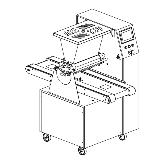
4.4. MAIN COMPONENTS 1 - Frame The frame is made of steel, aluminium alloy and stainless steel, covered by stainless steel panels that are fast and easy to clean and sanitize. 2 - Conveyor The conveyor allows the tray to move forwards or backward for an accurate placement and for moving while the machine is dropping. -
Page 18: Working Areas
4.6. WORKING AREAS 4.6.1. MAXIDROP TWIST / MAXIDROP TWIST EVO Normal running direction The machine can be used by one operator only, who fills the hopper, feeds the trays and removes them. 1. Hopper filling area 2. Tray feeding area 3. -
Page 19: Products Overview
Multilayer long product Multilayer long product with rotation Flame shaped product Flame shaped product with rotation Zeppola Available on MAXIDROP MAXX and MAXIDROP MAXX EVO models only Available on MAXIDROP TWIST EVO and MAXIDROP MAXX EVO models only USE AND MAINTENANCE MANUAL... -
Page 20: Start-Up And Operation Checks
The operator has a stop push-button to stop the machine, in addition to an emergency stop push-button and safety devices on the safety guards. Press the stop push-button to stop production temporarily. In danger situations, use the emergency stop push-button to immediately stop the machine. www.mimac.com... -
Page 21: Main Switch
Description Colour Function Touch screen panel Programming / selection of the product to be made Enabling push-button Blue Enables the machine to start production Stop push-button Interrupts the production cycle Start push-button Green Starts the production cycle Emergency stop push-button Red/Yellow Stops the machine in an emergency Flash drive connection for program backup/resetting and... -
Page 22: Preliminary Operations
3. Carefully push the dosing group towards the structure, aligning the motor roller with the relative 4. Insert the upper section of the head supports coupling 5. Insert the hopper and fasten it using the relative stop 6. Close the hopper guard nuts www.mimac.com... -
Page 23: Inserting The Pump Type Dosing Unit
5.4.2. INSERTING THE PUMP TYPE DOSING UNIT 1. Lay the head on the supporting rods 2. Delicately insert the two rollers into the cavity 4. Carefully push the dosing group towards the 3. Position the front cap and fasten it using the relative structure, aligning the motor roller with the relative stop nuts coupling... -
Page 24: Inserting The Mould
If the wire does not cut the dough that exits from the moulds simultaneously and with the same tightness, the product will not fall onto the trays in aligned rows. Make sure that the steel wire is placed and tensioned correctly. www.mimac.com... - Page 25 1. Pull the check pins up (parts 1 and 2), insert the tray into its seats and release the check pins. 2. Fully unscrew screw No. 2 and loosen screw No. 1. 3. Make sure the arms are aligned with the die, carefully pushing the frame forward and backward manually.
-
Page 26: Inserting/Replacing The Steel Wire
1. Lift the rear mobile guard. 2. Pull the frame check pins up. 3. Remove the frame from its seat. 4. Delicately remove the worn/broken wire, making sure to have removed all of it, even from around the tightening screws. www.mimac.com... - Page 27 5. Insert the replacement wire, passing it through the holes of the arms, being very careful not to bend it excessively. 6. Fix the first end of the steel wire, inserting it into the adjustment screw hole and wind it around the screw a few times in order to guarantee a perfect hold.
-
Page 28: Checking The Safety Devices
5.5. CHECKING THE SAFETY DEVICES 5.5.1. MAXIDROP TWIST / MAXIDROP TWIST EVO Always check the safety devices before using the machine: 1. press the emergency stop push-button on the control panel (part 1); 2. activate the safety micro-switches by lifting the mobile guards of the machine (part 2);... -
Page 29: Maxidrop Maxx / Maxidrop Maxx Evo
5.5.2. MAXIDROP MAXX / MAXIDROP MAXX EVO Always check the safety devices before using the machine: 1. press the emergency stop push-button on the control panel (part 1); 2. activate the safety micro-switches by lifting the mobile guards of the machine (part 2 and part 3); 3. -
Page 30: Machine Use
Pressing the “OK” key a new program is created and added at the bottom of the list of existing programs. When closing the selection frame, a keyboard comes up for punching in the program name. The program suggests a standard name like for example PROG_XXX. www.mimac.com... -
Page 31: Parameters' Menu
Press on the image to select the product type Page scroll 6.3. PARAMETERS’ MENU The main frame also shows the parameters’ menu of the program that is being used. Pressing on one of the active areas, highlighted below, the parameters relative to the selected menu are displayed in the space reserved for them. -
Page 32: Description Of Product Parameters
Keys for page scrolling Pressing this key one moves to the previous parameters page. Pressing the horizontal arrows, one moves to the feed menu. Keys for viewing the feed and lifting parameters. Pressing the vertical arrows, one moves to the lifting menu. www.mimac.com... -
Page 33: Dosage Parameters
6.4.1. DOSAGE PARAMETERS Parameter Icon Description If selected, the type of dosing group is set to rollers. Head type If selected, the type of dosing group is set to pump. Dosing rollers rotation time. Regulates the quantity of Dropping time product to be dosed. - Page 34 Conveyor speed during the dosing phases on the layer in the long multilayer second layer. product Conveyor speed during the dosing phases on the third layer. Single or multi-step If selected, the machine performs a single dosage for dosage mode each row. www.mimac.com...
- Page 35 Parameter Icon Description If selected, the machine performs multiple dosages for each row. Distance between the first dosage and the last in multi- Multi-step product length step products. Available only if the multi-step product is enabled. Number of dosages performed for each multi-step Number of dosages per product.
-
Page 36: Nozzles Rotation Parameters
Allows to select the rotation mode during the initial uniformity, for flame uniformity phase of the dosage, for flame products. products Rotation mode during Allows to select the rotation mode during the conveyor lowering lowering phase, for flame products. www.mimac.com... - Page 37 Parameter Icon Description Rotation speed of the nozzles during the dosing of the first layer. Nozzles rotation speed during the dosing of the Rotation speed of the nozzles during the dosing of the different layers of the second layer. multilayer products Rotation speed of the nozzles during the dosing of the third layer.
-
Page 38: Wire-Cutting Parameters
If selected, the movement of the belt at the end of the dosing, in order to prevent the formation of the tip, takes Scrape direction place in the same direction as that of advance during the dosage. The value next to it indicates the length of the movement. www.mimac.com... - Page 39 Parameter Icon Description If selected, the movement of the belt at the end of the dosing, in order to prevent the formation of the tip, takes place in the opposite direction of that of advance during the dosage. The value next to it indicates the length of the movement.
-
Page 40: Lifting Parameters
Distance between the nozzles and the tray when dosing the first layer. Dosage height of each Distance between the nozzles and the product when single layer in fixed dosing the second layer. multilayer products Distance between the nozzles and the product when dosing the third layer. www.mimac.com... -
Page 41: Copying A Program
Parameter Icon Description Distance between the nozzles and the tray when dosing the first layer. Dosage height of each Distance between the nozzles and the product when single layer in long dosing the second layer. multilayer products Distance between the nozzles and the product when dosing the third layer. -
Page 42: Protecting Programs With A Password
If the user is set on TECHNICIAN the operator can carry out all the operations an ADVANCED user can perform. TECHNICIAN Moreover, it can modify the machine parameters The default password is 3050 SELLER Restricted to the vendor. Advanced BUILDER Restricted to the manufacturer. DMIN Restricted to the manufacturer. www.mimac.com... -
Page 43: Program Backup/Restore
6.8. PROGRAM BACKUP/RESTORE 6.8.1 BACKUP Through the backup procedure it is possible to save programs and machine data in a pendrive. 1. Access the advanced parameter area and press the “start” key. Wait for the frame below to appear: 2. Insert the USB flash drive in the port located at the back of the touchscreen or, if it is foreseen, in the port located on the front control panel. -
Page 44: Warnings On Programming
Before starting production, make sure that the Initial Space parameter makes it possible to have the correct distance between the nozzles and the tray edge, above all if the nozzles used are of the off-centre type. MIMAC ITALIA is not liable for any damage caused by incorrect machine programming. www.mimac.com... -
Page 45: Starting Production
6.10. STARTING PRODUCTION 4. Connect the power cable to the mains. 5. Fit the dosing unit, die and selected nozzles. 6. Turn the main switch to "ON". 7. Place the dough in the hopper. 8. Make sure the emergency stop push-button has not been pressed and that the guards are not open. 9. -
Page 46: Key To Manual Control Icons
The machine in start state is required. Nozzles rotation command As long as the button is pressed, the nozzles rotate clockwise. The machine in start state is required. Indicates the position of the nozzles expressed in Angle measurement degrees (°). www.mimac.com... -
Page 47: Wire-Cutting Control Icons
6.11.3. WIRE-CUTTING CONTROL ICONS Parameter Icon Description If selected, disables manual controls for wire-cutting. The machine must not be in the start state. Enabling wire-cutting commands If selected, enables the possibility of using manual controls for wire cutting. The machine must not be in the start state. Wire-cutting speed Speed of wire-cutting system Wire-cutting movement continuously until the start... -
Page 48: Lifting Control Icons
Before restarting production, make sure the emergency situation has stopped, then reset the emergency stop push- button, press the enabling push-button and after this the start push-button. Stopping the machine with the emergency stop push-button resets the production cycle. www.mimac.com... -
Page 49: Setup And Diagnosis
7. SETUP AND DIAGNOSIS 7.1. MACHINE PARAMETERS The machine parameters are inserted during the test phase by our qualified technicians. Unauthorized people must NOT modify these parameters for any reason whatsoever. The Producer is not liable for any faults, breakages or damage that are traceable to the unauthorized modification of these parameters. - Page 50 Useful to guarantee operation continuity of the Modbus wire-cut inverter machine till the inverter is replaced. Modbus lifting cam inverter SERVICE Parameter Description Enables the HMI remote connection. Password Password to enter after starting the HMI remote connection. Teleservice Starts the remote-assistance mode. www.mimac.com...
- Page 51 SECURITY Parameter Description Autologin Selects what basic user is initialized at the machine switch-on. Sets the user’s session duration after which the user set in the automatic User session expired login parameter is re-initialized. LIFTING Parameter Description Encoder coefficient Number of encoder pulses for each unit of displacement. Maximum encoder pulses Maximum number of encoder pulses per unit of time.
- Page 52 Revolutions per minute of Maximum number of revolutions the slow reducer spindles makes in a slow spindle minute. Teeth number on machine Number of teeth of the gear assembled to the reducer. sprocket www.mimac.com...
-
Page 53: Diagnostics Screen
7.2. DIAGNOSTICS SCREEN Pressing on the icon one can access the technical visualization page. This page shows the status of inputs and outputs of the line’s control electronics. Please refer to the wiring diagram. Navigation menu Name Icon Description Pressing the icon, you will go to the plc inputs and Input/output PLC outputs diagnostic page. -
Page 54: Plc's Inputs And Outputs
Output not active PLC Outputs Output active 7.2.2. DOSING MOTOR This page shows the status of the dosing unit inverters Please refer to the machine’s wiring diagram to find the meaning of each input. Torque output from the inverter Inverter inputs www.mimac.com... -
Page 55: Conveyor Advance Motor
Name Symbol Description Forward input. Reverse input. Digital inputs S1 input, reset inverter. S2 input, inverter enable. Inverter analog input, through which the PLC regulates Analog inputs the rotation speed of the motor. Expressed in Volt. Inverter output frequency. Output frequency Expressed in Hertz. -
Page 56: Lifting Motor
• The second digit indicates the next position the machine table must reach according to the selected working cycle. Also in this case the quota is expressed in millimetres. www.mimac.com... -
Page 57: Nozzles Rotation Motor
7.2.5. NOZZLES ROTATION MOTOR This page shows the management of the nozzle rotation motor. Please refer to the machine’s wiring diagram for further information. Nozzle position PLC command Name Symbol Description Run control from the PLC to the nozzle rotation motor drive card. -
Page 58: Wire-Cutting Motor
Reverse input. Digital inputs S1 input, reset inverter. S2 input, inverter enable. Inverter analog input, through which the PLC regulates Analog inputs the rotation speed of the motor. Expressed in Volt. Inverter output frequency. Output frequency Expressed in Hertz. www.mimac.com... -
Page 59: Alarms And Signals
7.3. ALARMS AND SIGNALS Accessing the alarm page in standard conditions, while no alarms or warnings are active, one can display a list showing the history of messages and alarms, with indication of the time the PLC detected the signal. Press CLOSE to exit this page and move to the previous one. - Page 60 Nozzle drive alarm Make sure the rotary mould has been inserted correctly. Clean the rotary mould thoroughly. Soften the dough. The machine is paused. Pause Press the start push-button to begin production. Press the stop push-button to reset the work cycle. www.mimac.com...
- Page 61 Message Causes, checks and possible solutions The photocell beam has been interrupted. The reflector is dirty or worn out. The photocell is dirty or positioned incorrectly. The photocell is worn out or positioned incorrectly. Photocell alarm Make sure there are no objects between the photocell and its reflector. Clean or replace the reflector.
- Page 62 • If the "Table overtravel alarm (bottom)" cuts in, press the icon together with the start push-button. • Keep the icon and the start push-button pressed until the alarm message disappears from the notification area. www.mimac.com...
-
Page 63: Cleaning
Washing the die elements at high temperatures is not recommended. MIMAC ITALIA is not liable for any damage and/or deformation that may be caused by temperatures above 50 °C. If parts are washed in a part washer, wait until they cool or cool them manually under cold running water. -
Page 64: Stationary Mould Disassembling And Cleaning
3. After unscrewing the blocking nuts, remove the upper plate 4. Remove the spacers 5. Remove the gears 6. Clean the nozzles thoroughly 7. Clean each one of the mould components 8. Dry and wait for all parts to cool down www.mimac.com... -
Page 65: Roller Type Dosing Unit Disassembling And Cleaning
8.4. ROLLER TYPE DOSING UNIT DISASSEMBLING AND CLEANING 1. Remove the front guard after removing the blocking nuts. 2. Lift the hopper guard. 3. Slightly withdraw the dosing unit. 4. Lift and remove the hopper after unscrewing the locking nuts. 5. -
Page 66: Pump Type Dosing Unit Disassembling And Cleaning
8. Remove the back cover of the cavity of the rollers after removing the fixing screws and remove the gasket. 9. Carefully wash all components using hot water. 10. Before reassembling the dosing unit, dry all parts and wait for them to cool down. www.mimac.com... -
Page 67: Maintenance
9. MAINTENANCE 9.1. GENERAL INFORMATION Maintenance operations must only be carried out by qualified and authorized technicians only. Unless otherwise indicated, maintenance must be carried out with the machine stopped and disconnected from the mains (machine in a safety condition). If it is necessary to start the machine with the guards removed to make maintenance/adjustment the technician must keep unauthorized persons away. -
Page 68: Dismantling And Disposal
Separating waste correctly helps avoid possible negative effects on the environment and health, and encourages the reuse and/or recycling of the materials used to produce the apparatus. Administrative sanctions foreseen by the laws in force are applied to holders who dispose of the product in an unlawful manner. www.mimac.com...
Need help?
Do you have a question about the MAXIDROP TWIST and is the answer not in the manual?
Questions and answers