Table of Contents
Advertisement
Quick Links
Advertisement
Table of Contents

Related Manuals for CAMPSMART RAPID BAR 600

Summary of Contents for CAMPSMART RAPID BAR 600
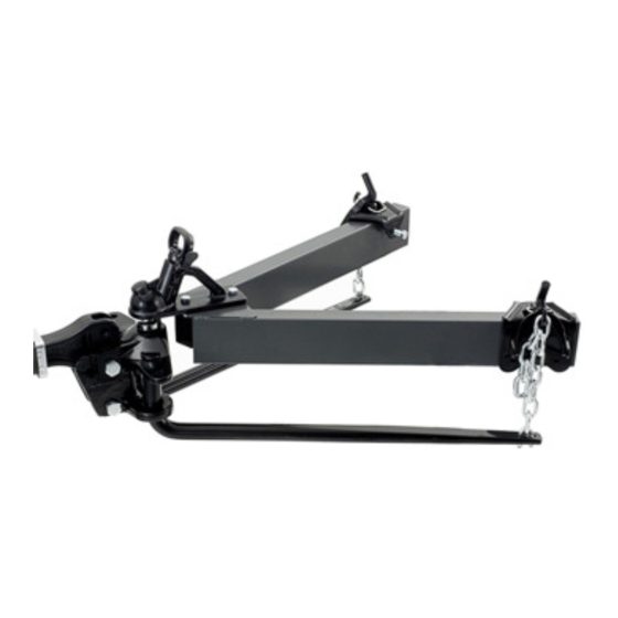
- Page 1 RAPID BAR 600 RTE042 WEIGHT DISTRIBUTION KIT - 275KG BA INSTRUCTION MANUAL...
-
Page 2: Table Of Contents
Table of Contents Sizing WD and Trailer Hitch Systems Initial Set-Up Optional Shim Kit Initial Hook Up Lubrication Surge Brakes Warnings Maintenance Towing Tips 6 Months Limited Warranty... -
Page 3: Sizing Wd And Trailer Hitch Systems
SIZING WD AND TRAILER HITCH SYSTEMS 1. Refer to the provided Consumer Information to weigh loaded trailer tongue to determine the proper system size. 2. C hoose a system with a tongue rating at or above the actual trailer tongue weight. 3. T he tongue rating of the trailer hitch must meet or exceed the measured tongue weight of the trailer. The OEM hitches may not be rigid enough for tongue weight and may need to be replaced (too much flex and won’t carry load). 4. The total trailer gross weight rating must never exceed the tow vehicle’s rated gross tow rating. INITIAL SET-UP 1. Line up the tow vehicle and trailer on level pavement, in the straight- ahead position, uncoupled. 2. L evel the trailer and measure and record the distance from the ground to the top of the coupler. (Fig.1). 3. S elect a hitch ball with a diameter that matches the trailer coupler size. The three most common sizes are 1-7/8”, 2”, and 2-5/16” . Select ball with 1-1/4” or 1“ threaded shank that is V-5 rated equal to or greater than the trailer’s gross vehicle weight rating (GVWR). WARNING: Raised balls usually have reduced load ratings. The Ball rating MUST equal or exceed the trailer GVWR. - Page 4 4. Attach hitch the ball to the ballmount (A). Standard height hitch balls with 1-1/4” shanks are supplied with lock washers and nuts (If you must use a 1” shank ball, use the provided 58184 bushing (B) to reduce the hole size in the ballmount (A) to 1”). Always use a lock washer placed between the ballmount and the nut. Unless otherwise specified by the ball manufacturer, torque the ball nut to 450 ft/lbs for the 1-1/4” nut, 250 ft/lbs for the 1” nut. 5. Some installations may require a longer draw bar (C). Extended bumper guards, pickup truck “caps”, or rear mounted spare tyres can limit turn angles unless a longer bar is used. Individual draw bars (C) are available in various sizes. 6. Insert the draw bar (C) into the hitch box and install a pull pin (D) and spring clip (E). A draw bar may be used in either the up or down position (see Fig. 2). NOTE: The ball height should be greater than the coupler height by approximately 3/4 to 1” (measured in step 2) to compensate for vehicle squat. For vehicles with air springs, air shocks or an automatic levelling system, check the vehicle owner’s manual. Unless otherwise specified, level the trailer with the vehicle loaded as it will be when towing before setting ball height and attaching the trailer. Highest Position Lowest Position Fig. 1 Fig. 2 7. Position the ballmount on the draw bar so that the ball will be approximately 3/4” higher than the coupler when in the center of its tilt adjustment. Insert 3/4 X 4 1/2” bolt (F) through the lower hole in the ballmount and install a 3/4” lock washer (G) and a 3/4” nut (H). Rotate the ballmount up to approximately the center of the tilt adjustment and install one adjustment washer (J) on a 3/4 x 5 1/2“ bolt (K) and insert the bolt into the upper slot in the ballmount. NOTE: The adjustment washer hole is not center and can be rotated 180° for maximum head adjustment or half adjustment steps (see below). Install the second adjustment washer (oriented the same as the first), lock washer, and the nut on the other side. Torque the 3/4 nuts (K) to 300 ft-lbs (If a large enough torque wrench is not available, torque nuts to 150 ft-lbs, then turn nuts an additional 1/4 turn - DO NOT lubricate the threads).
-
Page 5: Optional Shim Kit
INITIAL SET-UP (continued) Adjustment washer hole oriented vehicle Adjustment washer hole oriented vehicle forward: Max head tilt rearward rearward: Max head tilt forward OPTIONAL SHIM KIT Use the shim provided when needed to fill any gap between the Weight Distributing Head shown below and the hitch bar used in the particular application. It is easier to install the shim from the top down as shown below. In doing so, you will encounter one of three scenarios: 1. The shim will go all the way down to line up with the bottom hole. If this is the case, use the entire shim in the gap. NOTE: It is conceivable that in some rare combinations, two shims could be used. In these cases, contact Customer Service for a free additional shim service kit #58207. 2. T he shim will not begin to fit between the head and the hitch bar. If this is the case, discard the shim and continue installation. The existing gap is acceptable. 3. T he shim will not go in far enough to reach the bottom hole. If this is the case, cut the shim in half and use only the top half for the top bolt. Discard bottom half of shim. -
Page 6: Initial Hook Up
INITIAL HOOK UP NOTE: The car and trailer should be loaded and ready for travel before final leveling. 1. Pick a reference point on the front wheel well. Measure and record the distance to the pavement. From the front wheel well to the pavement. 2. A ttach chains to spring bars using U-bolts, flat washers, and locknuts. Let 2-3 threads protrude below lthe ocknut. The chain must not bind. Standard Spring Bar 3. Lower the coupler onto the ball with a tongue jack and close the coupler latch. 4. Insert the round end of the spring bar into the lower socket of the ballmount and push upward. Line up the notch in the spring bar with the tab in the upper socket, and push up until seated. Rotate the spring bar so that it is in line with the trailer frame to lock it into place (the spring bars will fit on either side, as they are not made right or left handed). Repeat the procedure for the other bar. NOTE: To release the spring bar, lift up on the bar and rotate so that the notch in the spring bar and the tab in the upper socket are in line, then allow the bar to drop out of the ballmount. 5. Position the snap up brackets on the trailer “A” frame so that the chain at the end of the spring bar is approximately vertical. Turn the 1/2 x 3-1/2 bolt until it contacts the frame. Then, with the wrench, tighten 1/4 turn. DO NOT OVERTIGHTEN. 6. Raise the trailer tongue and rear of the vehicle with the tongue jack. Lower the yoke of the snap up bracket until it is parallel with the ground, and slip the closest link over the hook. (If there are less than 4 links between the... -
Page 7: Lubrication
INITIAL HOOK UP (continued) 7. Lower jack. Re-measure the front wheel well reference point. The front wheel well height should be equal to or lower than the original measurement. If the front wheel well height is higher than originally measured, reduce the number of links between the yoke hook and spring bar (4 links min.) and recheck the wheel well measurement. If the front wheel well is lower than originally measured, increase the number of chain links between the yoke hook and spring bar and recheck the wheel well measurement. If the original wheel well height is not achievable, it is preferred that the wheel well height be lower after the spring bars are loaded. If there are no more chain links for adjustment, the head assembly must be tilted forward. The trailer must be uncoupled and the upper bolt removed from the head assembly. The head is then pivoted up as appropriate. Reassemble and recheck the wheel well height. LUBRICATION Place several drops of oil at spring bar / ballmount contact points each day of use. Excess oil, dirt, and grit should be wiped out whenever a trailer is uncoupled. SURGE BRAKES Some surge brakes will not work with weight distributing hitches. CHECK THE TRAILER AND/OR SURGE BRAKE OPERATING INSTRUCTIONS FOR ANY SPECIAL REQUIREMENTS REGARDING WEIGHT DISTRIBUTING HITCHES. Do not use sway control with surge brakes. WARNINGS LOADED BALL HEIGHT SHOULD NEVER BE GREATER THAN UNCOUPLED BALL HEIGHT. Front wheel overload and loss of rear wheel traction can result, and can lead to unstable handling, reduced braking... -
Page 8: Maintenance
DO NOT TOW MULTIPLE TRAILERS: Do not attempt to tow any type of trailer behind another trailer. Towing multiple trailers may cause severe instability, loss of control and/or structural failure, and may result in vehicle accidents, property damage and personal injury. Towing multiple trailers is illegal in many jurisdictions. FRONT-WHEEL-DRIVE VEHICLES: DO NOT ATTEMPT TO HOOK-UP OR TOW WITH REAR WHEELS OF TOWING VEHICLE REMOVED. Severe structural damage to towing vehicle, hitch, and trailer may result. A towing vehicle/trailer combination cannot be controlled adequately unless the towing vehicle’s rear wheels are carrying their share of the load. MAINTENANCE Keep the trunnions and sockets in the head assembly free of dirt and well lubricated. Excessive wear in this area may indicate overload or inadequate lubrication. Some elongation of socket openings “seat in” is normal. Keep the head assembly exterior clean, especially the trunnion sockets. Do not allow dirt or stones to lodge between the trunnions and the head. Keep the hitch painted to prevent rust and maintain a good appearance. (Do not paint over labels) AT THE BEGINNING OF EVERY TOWING DAY: • Add a drop of oil at the trunnion contact areas with ball mount. - Page 9 TOWING TIPS (continued) PULL OVER AND MAKE A THOROUGH INSPECTION. CORRECT ANY PROBLEMS BEFORE RESUMING TRAVEL. CHECK YOUR EQUIPMENT: Periodically check the condition of all your towing equipment and keep it in top condition. TRAILER LOADING: Proper trailer loading is important. Heavy items should be placed close to the floor near the trailer axle. The load should be balanced side-to-side and firmly secured to prevent shifting. For most trailers, the tongue weight should be around 10–15 percent of the gross trailer weight.. Too low a percentage of tongue weight will often produce a tendency to sway. Excess weight on the tongue can also lead to sway and damage the hitch and / or tow vehicle. SWAY CONTROLS: A sway control can help minimise the effects of sudden maneuvers, wind gusts, and buffeting caused by other vehicles. The use of a sway control is recommended for trailers with large surface areas, such as travel trailers. TIRE INFLATION: Unless specified otherwise by the towing vehicle or trailer manufacturer, tires should be inflated to their maximum recommended pressure. TOWING VEHICLE AND TRAILER MANUFACTURERS’ RECOMMENDATIONS: Review the owners’ manuals for your towing vehicle and trailer for specific recommendations, capacities, and requirements.
-
Page 10: Months Limited Warranty
6 MONTHS LIMITED WARRANTY Road Tech Marine will replace FREE OF CHARGE any part which proves defective in material or workmanship when presented to any Road Tech Marine store or returned to the factory. TRANSPORTATION CHARGES PREPAID, at the address below. THIS WARRANTY IS LIMITED TO DEFECTIVE PARTS REPLACEMENT ONLY. LABOR CHARGES AND/OR DAMAGE INCURRED IN INSTALLATION OR REPLACEMENT AS WELL AS INCIDENTAL AND CONSEQUENTIAL DAMAGES CONNECTED THEREWITH ARE EXCLUDED. Some states do not allow the exclusion or limitation of incidental or consequential damages, so the above limitation or exclusion may not apply to you. - Page 12 Distributed by: Electus Distribution Pty. Ltd. 320 Victoria Rd, Rydalmere NSW 2116 Australia www.electusdistribution.com.au Made in China...
Need help?
Do you have a question about the RAPID BAR 600 and is the answer not in the manual?
Questions and answers