Table of Contents
Advertisement
Quick Links
Advertisement
Table of Contents

Summary of Contents for Parker Balston Super Flow Tri-Gas Generator Series
- Page 1 Installation, Operation and Maintenance Manual Bulletin TI-LCMS-SF5000J Super Flow Tri-Gas Generators Super Flow Tri-Gas Generator Series Models LCMS-SF5000, LCMS-SF5001T, LCMS-SF5001NT Installation, Operation, and Maintenance Manual 1-800-343-4048 www.labgasgenerators.com...
-
Page 2: Explanation Of Warning Symbols
Installation, Operation and Maintenance Manual Bulletin TI-LCMS-SF5000J Super Flow Tri-Gas Generators Explanation of Warning Symbols Symbol Description Caution, refer to accompanying documents for explanation. Refer to the caution note indicated for explanation. Caution, risk of electric shock. Refer to the warning note indicated for explanation. - Page 3 Installation, Operation and Maintenance Manual Bulletin TI-LCMS-SF5000J Super Flow Tri-Gas Generators Super Flow Tri-Gas Generator Series Models LCMS-SF5000, LCMS-SF5001T, LCMS-SF5001NT Installation, Operation, and Maintenance Manual These instructions must be thoroughly read and under- department at 1-800-343-4048, 8AM to 5PM Eastern Time or stood before installing and operating this product.
-
Page 4: General Description
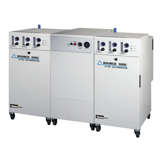
Installation, Operation and Maintenance Manual Bulletin TI-LCMS-SF5000J Super Flow Tri-Gas Generators General Description The Source LC/MS Super Flow Tri-Gas 5000 Generator Series are available in three models (see figures 1a,b,c): (1) LCMS-SF5000, Tri-Gas Generator, Compressor and Receiver Tank (visually integrated model) (2) LCMS-SF5001T, Tri-Gas Generator and Receiver Tank (3) LCMS-SF5001NT, Tri-Gas Generator The visually integrated system is engineered to produce pure nitrogen for curtain gas;... - Page 5 Installation, Operation and Maintenance Manual Bulletin TI-LCMS-SF5000J Super Flow Tri-Gas Generators Figure 3: Tri-Gas Generator Flow for LCMS-SF5000 and LCMS-SF5001T (one of two units shown) Figure 4: Tri-Gas Generator Flow for LCMS-SF5001NT (one of two units shown) Prefilters Two stages of high efficiency coalescing prefiltration are incorporated into the design of the Source 5000 to remove water and particulate contamination to 0.01 micron.
-
Page 6: Installation
Installation, Operation and Maintenance Manual Bulletin TI-LCMS-SF5000J Super Flow Tri-Gas Generators Hydrocarbon Removal The tower module is a stainless steel vessel filled with catalyst, equipped with a cartridge heater. During operation, hydrocarbons are oxidized into carbon dioxide and water vapor. The catalyst bed is maintained at the required temperature for optimal oxidation by the heater’s temperature controller. - Page 7 Installation, Operation and Maintenance Manual Bulletin TI-LCMS-SF5000J Super Flow Tri-Gas Generators Figure 6 Figure 5 Location Location of the generator with proper ventilation is critical. Install the generator in a clean, well ven- tilated area. To provide adequate ventilation and servicing for the generator, a minimum clearance distance of 30 inches in front and in the rear is required.
- Page 8 Installation, Operation and Maintenance Manual Bulletin TI-LCMS-SF5000J Super Flow Tri-Gas Generators The generator is for indoor use only. Do not install outdoors. The ambient temperature of the air surrounding the generator should not exceed 90°F (32°C). If the compressor is located in a totally enclosed room without ventilation, an exhaust fan with access to outside air must be installed.
- Page 9 Installation, Operation and Maintenance Manual Bulletin TI-LCMS-SF5000J Super Flow Tri-Gas Generators Figure 10 Tri-Gas Generator Voltage Selection Figure 9 Compressor 20A 250V (one Tri-Gas Generator shown) Receptacle for NA model Each Tri-gas generator is shipped with a tag at the power receptacle which specifies the factory setting of the voltage selector.
-
Page 10: Recommended Accessories
Installation, Operation and Maintenance Manual Bulletin TI-LCMS-SF5000J Super Flow Tri-Gas Generators Drains The compressor drain tube is a black nylon 1/4” tubing connecting the drain outlet to the provided disposal container (see figure 12). A blue silencer is provided to reduce the discharge noise. The Tri-Gas generator drain tube is also a black nylon 1/4”... -
Page 11: Operation
Installation, Operation and Maintenance Manual Bulletin TI-LCMS-SF5000J Super Flow Tri-Gas Generators Operation Start-up Check that the power cords of both the compressor and the two Tri-Gas Generators are connected to their proper power supply outlets. Check that the Tri-gas generators are not powered on (all LEDs are not lit). - Page 12 Installation, Operation and Maintenance Manual Bulletin TI-LCMS-SF5000J Super Flow Tri-Gas Generators Each cabinet has its own automatic water drain system. The compressor drain operates every 40 min- utes, opens for 2 seconds. In the Tri-gas generator, the two filter bowls drain every 5 minutes and the receiver tank drains every 30 minutes for less than one second.
-
Page 13: Power Interruption
Installation, Operation and Maintenance Manual Bulletin TI-LCMS-SF5000J Super Flow Tri-Gas Generators Pressure Interruption For Model LCMS-SF5000, If the compressed air pressure decreases less than 105 psig (7.2 barg), the yellow “Low Pressure” LED will illuminate and an audible alarm will sound (beeping every 2 seconds). -
Page 14: Maintenance
Installation, Operation and Maintenance Manual Bulletin TI-LCMS-SF5000J Super Flow Tri-Gas Generators Maintenance Maintenance tasks for the Tri-Gas Generator should be performed by trained personnel familiar with the service and safety precautions of electromechanical devices to avoid injury or damage. Parker highly recommends service be performed by a Parker trained technician only. Call the factory about PMP, the Preventative Maintenance Program. - Page 15 Installation, Operation and Maintenance Manual Bulletin TI-LCMS-SF5000J Super Flow Tri-Gas Generators Schedule 3 Schedule 3 (refer to figures 24A and 24B) Replace Quantity Hours Frequency Tri-Gas Generator Filter Element 5,000 1 year For Serial Numbers (P/N 100-09-DX) LCMS-SF5000NA: 1012A and above Filter Element 5,000 1 year...
-
Page 16: Intake Filter
Installation, Operation and Maintenance Manual Bulletin TI-LCMS-SF5000J Super Flow Tri-Gas Generators Cleaning If necessary, wipe the compressor or generator with a clean, dry cloth on an as-needed basis. Do not use water, aerosols or other cleaning agents on the units. Use of any liquid detergent to clean the units could pose an electrical hazard. - Page 17 Installation, Operation and Maintenance Manual Bulletin TI-LCMS-SF5000J Super Flow Tri-Gas Generators Table 1 - Grease Delivery SLAE03E Bearing 1st Pump 2nd Pump Orbit Scroll Bearing 5 times 4 times Pin Crank Bearing 4 times 4 times (Orbit Scroll side) Figure 27 Grease and Orbit Scroll Bearing Grease Pin Crank 1 Remove top and side service panels (see figure 8).
- Page 18 Installation, Operation and Maintenance Manual Bulletin TI-LCMS-SF5000J Super Flow Tri-Gas Generators Grease Fittings for pin crank bearings Figure 28 Grease Fittings for Pin Crank Bearings Note: The grease fitting located in the center of the pin crank bearing feeds only the orbit scroll side bearing.
- Page 19 Installation, Operation and Maintenance Manual Bulletin TI-LCMS-SF5000J Super Flow Tri-Gas Generators Caution! Do not attempt to remove the orbit scroll from the housing. 9 After installing half of the low pressure seal, carefully remove the seal from the channel to make sure the seal is properly locking onto the channel indentations located just past the high pressure seal.
- Page 20 Installation, Operation and Maintenance Manual Bulletin TI-LCMS-SF5000J Super Flow Tri-Gas Generators Schedule 2 and 3 Instructions These instructions describe the replacing of the two coalescing pre-filters, the four in-line filters, the two carbon modules, and the zero air tower module in the Tri-Gas generator. Coalescing Prefilters 1 Remove the front panel from the Tri-Gas generator by rotating the latch a quarter turn counter clockwise with a screwdriver.
- Page 21 Installation, Operation and Maintenance Manual Bulletin TI-LCMS-SF5000J Super Flow Tri-Gas Generators In-Line Filters There are four in-line filters requiring replacement (for model LCMS-SF5001NT three in-line filters). The replacement element (050-05-BX) is the same for all in-line filters (see figure 24A). By hand (or with wide-grip pliers, if necessary), rotate the bowl counter clockwise, remove and replace the filter element with a new one, return bowl, and hand tighten (see figures 34 &...
- Page 22 Installation, Operation and Maintenance Manual Bulletin TI-LCMS-SF5000J Super Flow Tri-Gas Generators 3 Remove black velcro strap from one carbon module (see figure 40). 4 Remove tubing from top of module (see figure 41). Remove tubing from bottom of module. 5 Pull out module and replace new. Insert tubing, top and bottom. 6 Perform steps 3 through 5 for the other two carbon modules.
-
Page 23: Tower Module
Installation, Operation and Maintenance Manual Bulletin TI-LCMS-SF5000J Super Flow Tri-Gas Generators Figure 42 Figure 43 Figure 44 Tower Module The tower module in the generator should be changed (when the “Low Temperature” LED is illumi- nated or blinking) to maintain the hydrocarbon removal specification for the unit. Contact the local representative for ordering information and pricing for a replacement tower module. -
Page 24: Fuse Replacement
Installation, Operation and Maintenance Manual Bulletin TI-LCMS-SF5000J Super Flow Tri-Gas Generators Figure 45 Inlet / Outlet Figure 46 Dryer Membrane Figure 47 Nut Figure 48 Disconnect Electrical Figure 49 Disconnect Electrical at PCB Fuse Replacement The Tri-Gas Generator fuses are located in the power receptacle on the top, rear side of the gen- erator. -
Page 25: System Specifications
Installation, Operation and Maintenance Manual Bulletin TI-LCMS-SF5000J Super Flow Tri-Gas Generators System Specifications System Specifications LCMS-SF5000 LCMS-SF5001T, LCMS-SF5001NT CSA Certification Standard CAN/CSA C22.2 No. 61010-1 same IEC Standard IEC 61010-1: 2001 same CENELEC Standard EN 61010-1: 2001 same UL Standard UL 61010A-1: 2002 same IEC 61010 Installation... - Page 26 Installation, Operation and Maintenance Manual Bulletin TI-LCMS-SF5000J Super Flow Tri-Gas Generators Cautions The flow meter reading is dimensionless. Read flowmeter at the middle of the ball. The ac- tual flow at various operating pressures is converted into SLPM (standard liters per minute) in the flow chart label on the unit, or in the flow charts section of this manual.
-
Page 27: Replacement Parts
Installation, Operation and Maintenance Manual Bulletin TI-LCMS-SF5000J Super Flow Tri-Gas Generators Replacement Parts (12) System Serial Number ending in no letter, “A”, or “C” Models NA Models UK, EU, JA, AU VERTICAL LCMS-SF5000 Compressor Replacement Parts (SF130) Part Number Part Number 5,000 Hour Maintenance Kit 1 MKSF5002 MK5002... - Page 28 Installation, Operation and Maintenance Manual Bulletin TI-LCMS-SF5000J Super Flow Tri-Gas Generators Nominal conditions for the charts are Temperature 68°F (20°C) and Ambient Pressure 14.7 psi [1013 mbar(a)]. The maximum pressure specification for the DRY AIR is 60 psig. Flow meter accuracy +/- 0.2 (Dewpoint -40°F). Shown flow rate is for one Tri-gas generator.
- Page 29 Installation, Operation and Maintenance Manual Bulletin TI-LCMS-SF5000J Super Flow Tri-Gas Generators The maximum pressure specification for the ZERO AIR is 110 psig. Flow meter accuracy +/-0.5 (<.1 ppm Hydrocarbons measured as Methane). Shown flow rate is for one Tri-gas generator. Double the flow rate for the total system output. Flow Rate (LPM) Pressure (PSIG) 1.75...
-
Page 30: Compressor Troubleshooting
Installation, Operation and Maintenance Manual Bulletin TI-LCMS-SF5000J Super Flow Tri-Gas Generators Troubleshooting Disconnect the electrical power and depressurize the generator before attempting any trouble- shooting activities according to the shut down steps in the operation section. Only trained per- sonnel using reasonable care should perform any troubleshooting activities. Determine whether the trouble is with the compressed air source or the Tri-Gas Generator. - Page 31 Installation, Operation and Maintenance Manual Bulletin TI-LCMS-SF5000J Super Flow Tri-Gas Generators Compressor Troubleshooting Symptom Probable Cause Corrective Action Excessive noise or vibration • Drive belts are loose • Tighten belts to specification • Drive belt has separated or • Replace drive belt flat spot •...
- Page 32 Installation, Operation and Maintenance Manual Bulletin TI-LCMS-SF5000J Super Flow Tri-Gas Generators Tri-Gas Generator Troubleshooting Symptom Probable Cause Corrective Action No Power • Power cord not plugged in • Plug in cord both ends at outlet and/or wall unit • No power at outlet •...
- Page 33 Installation, Operation and Maintenance Manual Bulletin TI-LCMS-SF5000J Super Flow Tri-Gas Generators Don’t Forget To: Complete and mail or fax in your Warranty Registration Card. Keep your product certification in a safe place. Call the Technical Services Department at 800-343-3038, 8AM to 5PM Eastern Time (North America only) or email at balstontechsupport@parker.com with any questions.
- Page 34 Installation, Operation and Maintenance Manual Bulletin TI-LCMS-SF5000J Super Flow Tri-Gas Generators Figure 54 Vertical Compressor Electrical Schematic 1, 60 Hz Unit 1-800-343-4048 www.labgasgenerators.com...
- Page 35 Installation, Operation and Maintenance Manual Bulletin TI-LCMS-SF5000J Super Flow Tri-Gas Generators Figure 55 Vertical Compressor Electrical Schematic 2, 50 Hz Unit 1-800-343-4048 www.labgasgenerators.com...
- Page 36 Installation, Operation and Maintenance Manual Bulletin TI-LCMS-SF5000J Super Flow Tri-Gas Generators Figure 56 Horizontal Compressor Electrical Schematic 3, 50 and 60 Hz Units Parker Hannifin Manufacturing Limited Parker Hannifin Corporation Printed in U.S.A. Bulletin TI-LCMSF500J Industrial Gas Filtration and Gas Separation & Filtration Division EMEA ©...
Need help?
Do you have a question about the Super Flow Tri-Gas Generator Series and is the answer not in the manual?
Questions and answers