Table of Contents
Advertisement
Available languages
Available languages
Quick Links
Advertisement
Table of Contents

Related Manuals for YILKAR YK 90 S Additional

Summary of Contents for YILKAR YK 90 S Additional
- Page 1 YILKAR Montaj Talimatı Installation Instruction YK 90 S İlave YK 90 S Additional SSH.MT.01.07 - TR-EN Değişiklik yapma hakkı saklıdır. Türkiye'de basılmıştır. © Yılkar Klima, 2023. The right to make changes is reserved. Printed in Turkey. © Yılkar Airconditioned, 2023...
- Page 2 09.02.2023 H.Kübra Şahin İlk yayın / First publication REVİZYON NO YAYIN TARİHİ REVİZYONU YAPAN KİŞİ REVİZYON NEDENİ REVISION NO PUBLISH DATE REVISING PERSON REASON FOR REVISION SSH.MT.01.07 - TR-EN Değişiklik yapma hakkı saklıdır. Türkiye'de basılmıştır. © Yılkar Klima, 2023. The right to make changes is reserved. Printed in Turkey.
-
Page 3: Table Of Contents
2.3 YK 90 S İlave Teknik Veriler ............. 3.Genel Bakış ......................6 3.1 YK 90 S İlave Genel Bakış ............... 6 3.1.1 YILKAR Split Ünite ................. 6 3.2 Genel Tanımlama ..................7 4.YK 90 S İlave Klima Montajı ................8 4.1 Genel Montaj Şeması... - Page 4 5. Klimanın Devreye Alınması ................26 6. Yedek Parçalar....................27 6.1. Evaporatör Yedek Parçalar ..............6.2. Diğer Yedek Parçalar ................7. Kullanım ve Bakım Önerileri................SSH.MT.01.07 - TR-EN Değişiklik yapma hakkı saklıdır. Türkiye'de basılmıştır. © Yılkar Klima, 2023. The right to make changes is reserved. Printed in Turkey.
- Page 5 4.Installation of Yılkar YK 90 S Additional ..............40 4.1 General Assembly Diagram ..............4.2 YK 90 S Additional U Connection Profiles Mounting ........ 41 4.3 YK 90 S Additional Unit Mounting ............43 4.3.1 Additional Unit Dimensions ............43 4.3.2 Additional Unit Roof Mounting ............
- Page 6 5. Commissioning the Air Conditioner ..............6. Spare Parts ......................6.1. Evaporator Spare Parts ................6.2. Other Spare Parts ..................7. Usage and Maintenance Recommendations ............SSH.MT.01.07 - TR-EN Değişiklik yapma hakkı saklıdır. Türkiye'de basılmıştır. © Yılkar Klima, 2023. The right to make changes is reserved. Printed in Turkey.
-
Page 9: Giriş
1. Giriş Bu talimat YK 90 S İlave iklimlendirme cihazının bir parçasıdır. Kurulum için tüm gerekli bilgiler açıklanmakta olup cihazın güvenli kullanımına dair bilgiler içermektedir. Yılkar klima montajını tam olarak yapmanız için lütfen bu montaj talimatını dikkatlice okuyunuz. Güvenli ve temiz yerde muhafaza edilmesi tavsiye edilir. Sorularınız için lütfen servise ve/veya müşteri hizmetlerine başvurunuz. -
Page 10: Garanti Ve Sorumluluk
1.1 Garanti ve Sorumluluk Garanti Şartları YILKAR müşterilerine satın aldıkları ürünlerin günümüz teknolojisine uygun ve hatasız olarak üretildiğinin garantisini vermektedir. Tüm YILKAR Yetkili Satıcıları, aracın hangi yetkili satıcı tarafından satıldığına bakmaksızın, garanti işlemi yapmakla yükümlüdür. Fabrikasyon hatalarda, ürün üzerindeki tüm parçalar teslim tarihinden itibaren 2 (iki) yıl süreyle garanti kapsamındadır. -
Page 11: Güvenlik Ve Yasal Düzenlemeler
Lütfen kendi güvenliğiniz için aşağıda yer alan kurallara dikkat ediniz: Tamir ve bakım işlemleri sadece gerekli eğitim almış ve yetkiye sahip uzman personele yaptırınız. YILKAR yetkili servislerine ait bilgileri , YILKAR’ın resmi web sayfası www.yilkarklima.com ’dan ulaşabilirsiniz. Cihaz çalışır durumda olduğunda elinizi ünitenin içine uzatmayın ve kondanser ile evaporatör fanına herhangi bir yabancı... -
Page 12: Tanım Ve Teknik Bilgiler
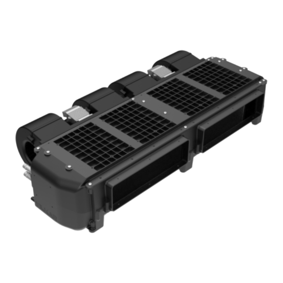
2. Tanım ve Teknik Bilgiler 2.1 YK 90 S İlave Nedir? YK 90 S İlave 15 koltuğa kadar olan minibüsleri iklimlendirmek için geliştirilen yenilikçi tasarımlı bir tavan üstü iklimlendirme cihazıdır. Kolay montajlanabilir olan ünite, bir evaporatör içerir. Bu ünitelerin aracın tavanına montajlanması... -
Page 13: Yk 90 S İlave Teknik Veriler
2.3 YK 90 S İlave Teknik Veriler Table.1 Teknik Bilgiler Tablosu Tavan Tipi Klima Ünitesi YK 90 S İlave 6 - 9 kW Soğutma Gücü (20472 - 30709 BTU/sa) (5159 - 7738 kcal/sa) Yağ Çeşidi PAG 100 yağ Yağ Miktarı 250 ccm Soğutucu Madde / Miktarı... -
Page 14: Genel Bakış
3. Genel Bakış 3.1 YK 90 S İlave Genel Bakış 3.1.1. YILKAR Spl t Ün te 311.02.YK090.01 (12V) EVAPORATOR UNITESI - YK 90 S 1 ADT 311.02.YK090.02 (24V) 501.21.YK090.01 (12V) EVAPORATOR GRUBU - YK 90 S - 2015 1 ADT 501.21.YK090.21 (24V) -
Page 15: Genel Tanımlama
3.2 Genel Tanımlama Evaporatör Evaporatör kondenserden gelen R134a soğutucu akışkanını valf yardımı buharlaştıran ve bu sayede ortam havasının soğumasını sağlayan klima sistemi elemanıdır. Valf Soğutucu akışkan basıncını düşürerek değiştirmesine yarayan klima sistemi elemanıdır. Röle Kartı Röle klima sisteminde akım ve voltaj değerleri yardımı... -
Page 16: Yk 90 S İlave Klima Montajı
4. Yılkar YK 90 S İlave Montajı 4.1 Genel Montaj Şeması Montaj şemasında iklimlendirme cihazı sisteminde hortumlar ile birbirine bağlanan bileşenler üzerinde R134a soğutucu akışkanının akış yönü ve alçak-yüksek basınç bölgeleri gösterilmektedir. MASTER SLAVE SELENOID VALF KONDENSER (OPSİYONEL) KOMPRESÖR VALF YK 90 S EVAPORATÖR İLAVE... -
Page 17: Yk 90 S İlave U Bağlantı Profilleri Montajı
4.2 YK 90 S İlave U Bağlantı Profilleri Montajı Bağlantı sacları evaporatörü araç tavanına ve birbirlerine sabitlemek amacıyla kullanılan öncelikle montajlanması gereken parçalardır. Montaj Adım 1: Öncelikle U bağlantı profillerini aracınızın tavanına uygun ölçülerde kesiniz. Montaj Adım 2: Kesilen U profillerinin ray-kulak parçalarını birbirine geçirerek montajını... - Page 18 Montaj Adım 4: Monoblok ünite için kullanılacak U bağlantı profilleri konumu aşağıda gösterilen ölçüde araç içinde tavan üzerinde işaretlenmeli ve matkap uçlu trapez M5x25 vida ile tavana montajı sağlanmalıdır. Bu bağlantı için 8 adet bağlantı vidası kullanılmaktadır. ARAÇ TAVANI EVAPORATÖR BAĞLANTISI İÇİN U ÇİFTLİ...
-
Page 19: Yk 90 S İlave Ünite Montajı
4.3 YK 90 S Ünite Montajı 4.3.1 YK 90 S Ün te Ölçüler Hava Akış Yönü 4.3.2 Ün ten n Tavan Montajı Montaj Adım 5: Evaporatör ünitesini araca daha önceden montajı yapılan U profillere matkap uçlu trapez altıköşe baş M5x25 vidalar ile uygun şekilde montajlayınız. Evaporatörün bulunduğu kısımda... - Page 20 İLAVE ÜNİTE ALT GÖRÜNÜŞ...
-
Page 21: Hortum Ve Rekorlar
4.4 Hortum ve Rekorlar İklimlendirme sistemi fabrika tarafından içinde 20 bar basınçla gönderilmektedir. Bağlantı noktalarındaki mevcut tapalar çıkarılırken içinde azot gazı bulunup bulunmadığı kontrol edilmelidir. YK 90 S ilave ünitesinde opsiyonel olarak selenoid valf kullanılmaktadır. Valf montajı için aşağıdaki montaj adımlarını uygulayınız. Selenoid valf kullanılmayacak ise tapaları... - Page 23 5/8 HORTUMU VE REKOR BAĞLANTISI 5/16 HORTUMU VE REKOR BAĞLANTISI Ø12 SU HORTUMU Su tahliye hortumu bağlantısı için, kelepçeler evaporatör Kademe su tahliye kısmındaki kademenin arkasından şekilde gösterildiği gibi sıkılmalıdır. Su tahliye hortumları su akışına engel olmayacak şekilde en az 2° açılık eğim verilmelidir.
-
Page 24: Klima Hortum Ve Rekor Bağlantıları
4.4.1 Kl ma Hortum ve Rekor Bağlantıları 4.4.1.1. Kl ma Hortumları Yılkar iklimlendirme sisteminde mevcut bulunan SAE-J 2064 type-E standartlarına uygun hortum çeşitleri, bu hortumlara ait minimum bükülme yarıçapı ve bu hortumlarla kullanılan rekorlar aşağıdaki tabloda mevcuttur. Tablo.2 Klima Hortum Tablosu HORTUM İÇ... -
Page 25: Kelepçe Ve Plastik Adaptörler
PLASTİK ADAPTÖR 5/16"-13,8 13/32''-17 5/8"-25,6 5/8"-25,6 4.4.1.4. Hortum ve Rekor Montajı 1-Öncelikle hortumları düz bir şekilde kesiniz. (1) 2-Rekorun geçeceği hortumun iç kısmını yağlayınız. 3-Rekorları hortumlara düzgün bir şekilde oturtunuz. (2)(3) 4-Pense yardımıyla kelepçeleri sıkınız. (4)(5) HORTUM YILKAR KOD: 212.01.P0000.05... - Page 26 13/32 , 5/8 ve 5/16 hortumlarını iç ve dış etkenlerden koruyacak şekilde montajlayınız. Aracın hareketli elemanlarından ve sıcak bölgelerinden uzak tutunuz, hattın geçeceği tüm keskin kenar ve köşelerden izole ederek montajı yapınız. Hortumları minimum bükülme yarıçapına uygun şekilde bükünüz. Tüm bağlantıları yapıldıktan sonra hortumları kablo bağları ile araca sabitleyiniz.
-
Page 27: Elektrik Bağlantıları
4.5 Elektrik Bağlantıları 4.5.1 Kontrol Ün tes Montajı Montaj yapılacak yüzey YLK 12/24 Kontrol Ünitesi Ünite konumu ergonomik olarak sürücünün erişilebileceği bir alanda düz bir yüzey olarak seçilmelidir. Montaj yüzeyi ölçüleri 90x45 mm olmalıdır. Kontrol paneli soketlerini şekilde gösterildiği gibi üniteye montajlayınız. Montajladıktan sonra kilitleri kontrol ediniz. - Page 28 Klimayı korumak için, ilave kofra seti kullanılmaktadır. Sigorta kutusu kolay ulaşılabilecek bir bölgeye montajlanmalıdır. 80A sigortayı, sigorta kutusundaki civataların olduğu bölgeye yerleştiriniz. Montaj kitindeki 16 mm B+ kablosunun M6 kablo ucunu sigortanın bir tarafına geçiriniz. Diğer M8 kablo ucunu aracın aküsünün (+) kutbuna yerleştiriniz. 16 mm B+ kablosunun M6 kablo ucunu sigortanın bir tarafına geçiriniz.
-
Page 29: Kablo Bağlantısı Ve Devre Şeması
4.5.2 Kablo Bağlantısı ve Devre Şeması İç Sıcaklık Sensörü ŞARJ DİNAMOSU (-) Şase KOFRA 80A (-) Şase FAN BLOWER FAN BLOWER MOTOR MOTOR SELENOID (-) Şase (-) Şase VALF (-) Şase... - Page 30 Açıklama Kablo Çap ve Renkleri 1. Fan Blower 1. Hız Turuncu 1.50 mm² Gri 1.50 mm² 2. Fan Blower 2. Hız Beyaz 1.50 mm² 3. Fan Blower 3. Hız 1 NU Kablo 0.50mm² 4. D+/ACC 2 NU Kablo 0.50mm² 5. Kumanda Besleme 3 NU Kablo 0.50mm²...
-
Page 31: Kontrol Ünitesi Genel Bakış
4.5.3 Kontrol Ün tes Genel Bakış Dijital kumanda, ünitedeki sıcaklık propları yardımıyla otomatik olarak ayarlanmış set değerleri sayesinde klimayı devreye alıp çıkartmaya yardımcı olur 32° 18° 21° Set sıcaklığı arttır Isıtma aç / kapat (Opsiyonel) Set sıcaklığı azalt Klape aç / kapat (Opsiyonel) Fan hızı... -
Page 32: Kontrol Ünitesi Çalıştırma
4.5.4 Kontrol Ün tes Çalıştırma 4.5.4.1 Soğutma Soğutma modunu başlatmak için, 32° soğutma butonuna basın. 18° Ekranda işareti çıktığında klimanız 21° soğutma modunda çalışır. 4.5.4.2 Isıtma (Ops yonel) Isıtma modunu başlatmak için, ısıtma 18° butonuna basın. 32° Ekranda işareti çıktığında klimanız 21°... - Page 33 Tablo.5 Teknik Bilgi Tablosu Besleme Voltajı 12 V - 24 V Ort. Elektriksel Tüketim 400 mA @12V @25°C Çalışma Sıcaklığı -10° C --- +45° C Hata Kodları Hata kodu 21° E 1 : İç Sıcaklık Sensörü Açık Devre Oluşma Nedeni: Kablo kesilmiş veya soket çıkmış olabilir. Sensör arızalanmış veya kırılmış...
-
Page 34: Klimanın Devreye Alınması
5. Klimanın Devreye Alınması Azot İle Sistemin Kaçak Kontrolü; Sisteme Azot gazı verildikten sonra sabunlu su ile kaçak kontrolü yapılır. Bu aşamada bakılması gereken noktalar rekor bağlantılarıdır. Bağlantı noktalarında hava kabarcığı olup olmadığı gözlemlenmelidir. 2. Sistemin Vakum Pompası İle Vakumlanması; Kompresör tarafından bağlanan vakum pompası... -
Page 35: Yedek Parçalar
6. Yedek Parçalar 6.1 Evaporatör Yedek Parçalar ALM EVAPORATÖR BATARYA x1 ADT 104.01.12007.01 331.04.RLK02.01 (12V) ROLE KARTI URT - YLK626 - 2015 / 2016 - 12V x1 ADT 331.04.RLK02.02 (24V) 105.10.BL12N.B1 (12V) FAN - BLOWER - 12 V BASKURT 700 x2 ADT 105.10.BL24N.B1 (24V) HAVA EMIS IZGARA PLASTIK - 4 - SIYAH x1 ADT 501.24.HEIPL.11... -
Page 36: Diğer Yedek Parçalar
6.2 Diğer Yedek Parçalar 32° 18° 21° KONTROL UNITESI - YLK 12/24 V x1 ADT KOFRA x1 ADT 105.01.KU010.01 503.92.KFSET.01... - Page 37 ünitenin kullanıldığı araca göre ölçü, adet ve çeşitlilik açısından farklılık gösterebilmektedir. Tamir işlemleri esnasında her zaman orijinal yedek parça kullanılmalıdır. YILKAR tarafından onaylanmamış olan parçalar, ünitenin güvenliğini ve düzgün çalışmasını olumsuz etkileyebilir. Bu tür durumlarda ünite GARANTİ kapsamından çıkar.
-
Page 38: Kullanım Ve Bakım Önerileri
7. Kullanım Ve Bakım Önerileri İklimlendirme cihazının işleyişini iyileştirmek için sistemin rutin bakımını yapınız. Bakım ve temizleme işlemleri için iklimlendirme cihazının kapağını açmadan önce, aracın akü bağlantısını kesiniz. Sistemi temizlerken elektrikli bileşenleri koruyunuz. Her mevsim başlangıcında, elektrikli bileşenler dâhil sistemin tüm bileşenlerini muayene ediniz. Yılda iki kere, kompresör izleyen kayışının gerginliğini kontrol ediniz;... - Page 41 1. Introduction This instruction is part of the YK 90 S Additional air conditioner. All necessary information for installation is explained and includes information on safe use of the device. Please read this installation instruction carefully in order to fully install Yılkar air conditioner.
- Page 42 1.1 Warranty and Liability Warranty conditions YILKAR assures its customers that the products they buy are manufactured in accordance with today's technology and without any errors. All YILKAR Authorized Dealers are obliged to carry out warranty transactions regardless of which authorized dealer the vehicle is sold by.
- Page 43 1.2 Security and Legal Regulations Read this service manual carefully before operating your YK 90 S Additional model roof type air conditioner. In case of problems that may occur as a result of improper use conditions, the warranty is canceled and compensation claims are not taken into account.
-
Page 44: Definition And Technical Information
2. Definition and Technical Information 2.1 What is YK 90 S Additional? YK 90 S additional is an innovative designed air conditioning device developed for air conditioning minibuses up to 15 seats. The easy-to-install unit includes an evaporator. These units must be mounted on the roof of the vehicle and connected to the compressor via hoses circulating R134a refrigerant. -
Page 45: Yk 90 S Additional Technical Data
2.3 YK 90 S Additional Technical Data Table.1 Air Conditioner Technical Data Roof Type Air Conditioning Unit YK 90 S Additional 6 - 9 kW Cooling Power (20472 - 30709 BTU/h) (5159 - 7738 kcal/h) Oil Type PAG 100 oil... -
Page 46: Overview
3. Overview 3.1 YK 90 S Additional Overview 3.1.1. YILKAR Spl t Un t 311.02.YK090.01 (12V) EVAPORATOR UNIT - YK 90 S 1 PCS 311.02.YK090.02 (24V) 501.21.YK090.01 (12V) EVAPORATOR GROUP - YK 90 S - 2015 1 PCS 501.21.YK090.21 (24V) -
Page 47: General Description
3.2 General Description Evaporator Evaporator is an air conditioning system element that evaporates the R134a refrigerant coming from the condenser with the help of a valve and thus cools the ambient air. Valve It is an air conditioning system element that provides the phase change by reducing the refrigerant pressure. -
Page 48: General Assembly Diagram
4. Yılkar YK 90 S Additional Installation 4.1 General Assembly Diagram In the assembly diagram, the flow direction of the R134a refrigerant and low-high pressure zones are shown on the components connected to each other by hoses in the air conditioner system. - Page 49 4.2 YK 90 S Additional U Connection Profiles Mounting Connection plates are the first mounting parts used to fix the evaporator to the vehicle roof. Assembly Step 1: First of all, cut the U-connection profiles to the dimensions suitable for the roof of your vehicle.
- Page 50 Assembly Step 4: The position of the U connection profiles to be used for the evaporator should be marked on the roof in the vehicle as shown below and mounted to the roof with a drill-tipped trapezoidal M5x25 screw. 8 connection screws are used for this connection. VEHICLE ROOF FOR EVAPORATOR CONNECTION...
- Page 51 4.3 YK 90 S Additional Unit Mounting 4.3.1 Add t onal Un t D mens ons A r Flow D rect on 4.3.2 Add t onal Un t Roof Mount ng Assembly Step 5: Assemble the evaporator unit to the U-profiles previously mounted on the vehicle with drill-tipped trapezoidal hexagon head M5x25 screws.
- Page 52 ADDITIONAL UNIT VIEW...
-
Page 53: Hoses And Fitting
Nitrogen gas in it. An optional solenoid valve is used in the YK 90 S additional unit. For valve assembly, follow the assembly steps below. If the solenoid valve is not to be used, remove the plugs and proceed directly to the union assembly after the nitrogen gas control. - Page 55 5/8 HOSE AND FITTING CONNECTION 5/16 HOSE AND FITTING CONNECTION Ø12 WATER HOSE For the water discharge hose connection, the clamps Stage must be tightened behind the stage in the evaporator water discharge section as shown in the figure. Water discharge hoses should be inclined at least 2°...
-
Page 56: Fitting Sets
4.4.1 A r Cond t oner Hose and F tt ng Connect ons 4.4.1.1. A r Cond t oner Hoses The hose types in compliance with SAE-J 2064 type-E standards available in Yılkar air conditioning system, the minimum bending radius of these hoses and the unions used with these hoses are given in the table below. - Page 57 1-First of all, cut the hoses straight. (one) 2-Lubricate the inner part of the hose where the union will pass. 3-Put the unions on the hoses properly. (2)(3) 4-Tighten the clamps with the help of pliers. (4)(5) HOSE YILKAR CODE: 212.01.P0000.05...
- Page 58 Assemble 13/32 , 5/8 and 5/16 hoses to protect them from internal and external factors. Keep away from the moving elements and hot parts of the vehicle, make the assembly by isolating it from all sharp edges and corners where the line will pass.
-
Page 59: Electrical Connections
4.5 Electrical Connections 4.5.1 Control Un t Mount ng Surface to be mounted YLK 12/24 Control unit The unit location should be ergonomically chosen as a flat surface in an area accessible to the driver. Mounting surface dimensions should be 90x45 mm. Assemble the control panel sockets to the unit as shown in the figure. - Page 60 To protect the air conditioner, an additional terminal box set is used. The fuse box should be installed in an easily accessible area. Place the 80A fuse in the area of the bolts in the fuse box. Pass the M6 wire end of the 16 mm B+ cable in the mounting kit to one side of the fuse.
- Page 61 4.5.2 W r ng and C rcu t D agram Internal Temperature Sensor GENERATOR (-) Şase TERMINAL BOX (-) Şase FAN BLOWER FAN BLOWER MOTOR MOTOR SELENOID (-) Şase (-) Şase VALve (-) Şase...
- Page 62 Description Cable Diameter and Colors 1. Fan Blower 1. Speed Orange 1.50 mm² 2. Fan Blower 2. Speed Grey 1.50 mm² 3. Fan Blower 3. Speed White 1.50 mm² 4. D+/ACC 1 NU Cable 0.50mm² 5. Power Control 2 NU Cable 0.50mm² 6.
-
Page 63: Control Unit Owerview
4.5.3 Control Un t Owerv ew The digital controller helps to activate and deactivate the air conditioner by automatically adjusted set values with the help of temperature probes in the unit. 32° 18° 21° Increase set temperature Heating on / off (Optional) Decrease set temperature Flap open / close (Optional) Changing the fan speed... - Page 64 4.5.4 Control Un t Operat ng 4.5.4.1 Cool ng To start the cooling mode, press the cooling button. When the snowflake sign appears on 32° 18° the screen, your air conditioner operates 21° in cooling mode. 4.5.4.2 Heat ng (Opt onal) To start the heating mode, press the 18°...
- Page 65 Table.5 Technical Information Table Supply Voltage 12 V - 24 V Average Electrical Consumption 400 mA @12V @25C Operating Temperature - 10 C --- + 40 C Fault Codes Fault code 21° E 1 : Inside Temperature Sensor Open Circuit Cause of Occurrence: The cable may have been cut or the socket may have come off.
-
Page 66: Commissioning The Air Conditioner
5. Commissioning the Air Conditioner Leakage Control of the System with Nitrogen; After giving Nitrogen gas to the system, leakage control is done with soapy water. The points to look at at this stage are the record connections. It should be observed whether there are air bubbles at the connection points. -
Page 67: Spare Parts
6. Spare Parts 6.1 Evaporator Spare Parts ALM EVAPORATOR BATTERY x1 PCS 104.01.12007.01 331.04.RLK02.01 (12V) RELAY BOARD - YLK626 - 2015 / 2016 - 12V x1 PCS 331.04.RLK02.02 (24V) 105.10.BL12N.B1 (12V) FAN - BLOWER - BASKURT 700 x2 PCS 105.10.BL24N.B1 (24V) AIR SUCTION GRILL PLASTIC - 4 - BLACK x1 PCS 501.24.HEIPL.11 VALVE - BLOCK - XINJING - 2220-01 x1 PCS... -
Page 68: Other Spare Parts
6.2 Other Spare Parts 32° 18° 21° DIGITAL AIR CONDITIONER CONTROL PANEL TERMINAL BOX x1 PCS x1 PCS 503.92.KFSET.01 105.01.KU010.01... - Page 69 Original spare parts should always be used during repairs. Parts not approved by YILKAR may adversely affect the safety and proper operation of the unit. In such cases, the unit is out of WARRANTY. For a fast and accurate shipment of spare parts, we kindly ask you to provide the following information: 1.
-
Page 70: Usage And Maintenance Recommendations
7. Usage and Maintenance Recommendations Perform routine maintenance of the system to improve the operation of the air conditioner. Before opening the cover of the air conditioner for maintenance and cleaning operations, disconnect the vehicle's battery. Protect electrical components while cleaning the system. At the beginning of each season, inspect all components of the system, including electrical components. - Page 72 Vehicle Heating Cooling and Ventilation Systems Phone : +90 224 215 53 28 (pbx) : +90 224 215 99 24 Address : Küçükbalıklı Mah. 580.Sok No:6 Osmangazi / BURSA / TURKEY www.yilkarklima.com...
Need help?
Do you have a question about the YK 90 S Additional and is the answer not in the manual?
Questions and answers