Table of Contents
Advertisement
Quick Links
Advertisement
Table of Contents

Summary of Contents for Fraunhofer STAN
- Page 1 STAN - The Stereoscopic Analyzer Manual: version 2.10-0-1-Z...
-
Page 2: Table Of Contents
Visualization of the Depth Structure ..................22 Color Adjustment Assistance ....................24 Color Temperature assistance ....................24 Brightness Assistance ......................25 Electronic Image Alignment ..................... 27 STAN – Specifications ......................28 HD-SDI Input Formats ......................28 Working Directory ........................ 29... -
Page 3: Introduction
STAN Processing Speed ......................33 Introduction The STAN (Stereoscopic Analyzer) is an assistance system for stereo shootings and 3D productions. An image-based scene analysis estimates in real-time the stereo geometry of the two cameras in order to allow an optimal alignment of the cameras and lens settings directly on the set. -
Page 4: First Steps
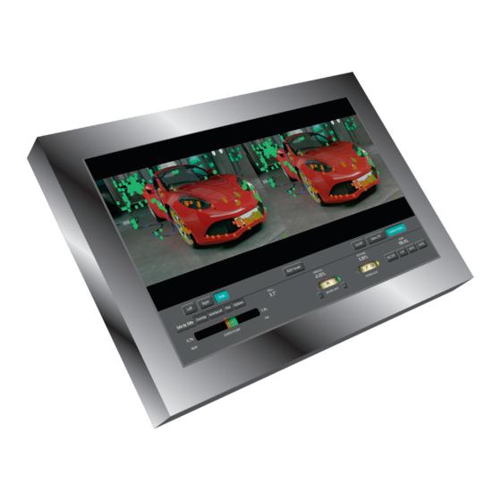
Figure 1: STAN's Graphical User Interface (GUI) First Steps Select Input Device If your PC system has more than one HD-SDI Input Device, choose the appropriate capture board from the Drop Down. Figure 2 illustrates this process. Supported capture boards are: ... -
Page 5: Select Input Raster
SDI Input Device Figure 2: Input Device selection: Options Video Input Device. The options menu is automatically opened after the start of the application when no camera signal matching the current Input Raster could be detected. After changing the Input Device, click Restart. -
Page 6: Adjust Vertical And Horizontal Flip
Input Raster could be detected. After changing the raster, click Restart. After the first start the STAN shows the video settings in the Options tab. It is necessary to select the proper Input Raster from the cameras. All supported Input Rasters can be found in the ANNEX. - Page 7 Figure 6: Stereoscopic image pair. The left image has been flipped vertically to compensate for flipping introduced by the mirror rig. You can start using the STAN now. Some stereo rig configurations might require to flip both cameras vertically and one camera...
- Page 8 As shown in Figure 7 you can also swap the left and right input channel. If for instance, the left camera is connected to the right STAN input channel (and the right camera to the left STAN input channel) you can use this feature to compensate this erroneous configuration.
-
Page 9: Calibrating Your Stereo Rig
Calibrating your Stereo Rig Mechanical Alignment One of the main features of the STAN is to provide assistance for the mechanical alignment of the rig. In Figure 9 the results of the geometrical analysis are illustrated. In this example, Roll, Vertical, Keystone, Tilt-Keystone, Y-Offset and Zoom settings are being evaluated and displayed. - Page 10 Figure 10: The Anaglyph Overlay mode can be used to get a visual feedback of the quality of the mechanical alignment. Red or cyan lines around horizontal object borders in the image are clear indicators of the presence of vertical disparities and thus a poor mechanical alignment.
- Page 11 Figure 11: Difference Overlay Mode. The Difference Overlay Mode shows the luminance difference between the two images. The Difference Overlay Mode is also widely used to perform the mechanical calibration of the rig and to choose a proper convergence plane. In the Difference Overlay mode, all objects in the convergence plane disappear.
- Page 12 Figure 12: Opacity Overlay Mode Figure 13: The Cut-Off Area mode combined with the Side-by-Side view mode allows for an optical feedback of possible calibration errors. In this example, the right camera suffers...
-
Page 13: Roll Error Adjustment
from a 1.1° roll error. The white and orange rectangles ins the two images coincide with the current camera geometry. Roll Error Adjustment The Roll error refers to a roll of the right camera with respect to the left camera. To reduce the roll, error, you can turn the appropriate knob on your stereo rig (e.g. -
Page 14: Tilt Keystone Error Adjustment
The Y-Offset indicates a height difference between the two cameras. The result is measured in percent and refers to the ratio of height error and interaxial distance. If you have an interaxial distance of 100mm and STAN indicates a Y-Error of 1%, your cameras are 1 mm off in height. -
Page 15: Calibration Options
Zoom-Level in a region around 99.9 % and 100.1 %. Note: When STAN measures 101.0% percent Zoom Level, the focal length of the right lens is by 1% longer than the focal length of the left lens. This will induce vertical disparities of ca. 5 pixels near the top and the bottom of the stereo images when using full HD resolution. - Page 16 Figure 14: Select the geometrical parameters to track: Options Fitting Roll / Vertical / Keystone / Tilt Keystone / Zoom / Y Offset...
-
Page 17: Depth Volume Adjustment
Depth Volume adjustment Measuring the Depth volume A key benefit of the STAN is the intuitive and precise measurement of the current Depth Volume. The value is shown in the center of the colored Depth Bar in the lower left region of the GUI. -
Page 18: Adjusting The Interaxial Distance / Stereo Baseline
Depth Budget requirements. The Depth Volume is constantly measured by STAN and displayed as shown in Figure 15. If this number exceeds the Depth Budget, the STAN will give a feedback to increase or shorten... - Page 19 Figure 17: The Depth Volume (1.7 % in this example) is compared to the Depth Budget (Total Parallax to be defined in the Options menu). Subsequently, STAN derives, in which direction, the interaxial distance needs to be changed. In this example, the red arrow to the right indicates that the interaxial distance needs to be increased drastically.
-
Page 20: Adjusting The Convergence / Angulation
Table 1: Description of the indications and advices given by STAN in order to find the best possible interaxial distance. Note: The colors of the interaxial distance arrows depend on the 3D-Settings in the Options menu. - Page 21 When you set the Maximum (Positive) Parallax as shown in Figure 19 to 1.0 %, STAN gives the respective advice to the stereographer to make sure that the far clipping plane does not exceed that value.
- Page 22 (negative) parallax. Strong frame of the near clipping plane. breaking might occur. accommodation-convergence conflict might occur. Table 2: Description of the indications and advices given by STAN in order to find the best possible convergence distance.
-
Page 23: Horizontal Image Translation (Hit) / Sensor Shift
Note: You can hide or show the convergence plane advices and/or the convergence plane gauge. To show the convergence plane advices, go to Options GUI and activate Angulation: Show. If you want to display the convergence plane gauge in the GUI, activate Angulation: Gauge in addition. - Page 24 A key feature of the STAN is the ability to visualize the depth of the scene elements directly in the GUI. This allows the stereographer to identify objects in the scene which are within or outside the desired depth volume.
-
Page 25: Color Adjustment Assistance
Color Adjustment Assistance Color Temperature assistance When using a mirror rig, the color temperatures will slightly between the two cameras. To visualize the color temperatures you can enable the RGB-Parade in the Side-by-Side view mode as shown in Figure 22. Figure 22: RGB-Parade. -
Page 26: Brightness Assistance
In order to shoot good 3D content, it is necessary to keep the Iris settings of the two lenses synchronized. Moreover for later color grading it is necessary to avoid over-saturated regions. STAN offers the Zebra visualization tool, which colors nearly saturated regions (Zebra 70%) or oversaturated regions (Zebra 100%) in violet. Figure 23 illustrates this feature. - Page 27 Figure 24: The Stripes visualization mode can be active in the Interlaced tab. Color and aperture differences are easy to recognize in this view mode. Additionally, you can find easily overview horizontal disparities in this view mode.
-
Page 28: Electronic Image Alignment
STAN can perform an electronic image alignment for the Overlay modes (i.e. Anaglyph, Difference, Opacity overlay) and the HDMI Output. To control the electronic image alignment, STAN has four buttons in the lower left part of the GUI as shown in Figure 25. -
Page 29: Stan - Specifications
STATIC: Once you have calibrated your rig, hit RECTIFY, and the STATIC. From now on, STAN displays only the remaining geometrical errors after the electronic image alignment. Use this button to check, if your calibration is still valid, or if you have to recalibrate your rig. -
Page 30: Working Directory
Working Directory The STAN software is located in a working directory containing the executables and the data files. Linux: /opt/HHI/STANapp Executables: /opt/HHI/STANapp/bin/STANapp Config file: /opt/HHI/STANapp/conf/stanapp-config.xml Windows: C:\Program Files\Fraunhofer HHI STANapp\ Executables: C:\Program Files\Fraunhofer HHI STANapp\bin Config file: C:\Program Files\Fraunhofer HHI STANapp\conf\stanapp-config.xml Config File settings Some advanced settings can only be changed in the config file. -
Page 31: Width And Height Of The Gui
GUI renderer Show true stan ctrl DeliverToRenderer true When both settings are set to true, STAN will activate the HDMI-Output window. Change back both settings to false, when you do not need the HDMI-Output. -
Page 32: Width And Height Of The Hdmi-Output Window
depthrange DoAutoSensorShift [true|false] Scan can automatically keep your scene within the desired Depth Budget and apply an Auto- HIT. Do enable the Auto-HIT set this settings to true. STAN will drive the settings between: stan depthrange MinSensorShift and stan ... -
Page 33: Auto-Interaxial
INTERAXIAL gauge and the CONVERGENCE gauge. Auto-Interaxial stan depthrange DoAutoInterocular true Make sure to enable Motor control first. STAN will drive the motor for the interaxial distance according to the settings made in Options 3D Settings. -
Page 34: Depth Plane Parallax Range
1 – high precision, slower processing 2 – moderate precision, faster processing 2 – low precision, very fast processing stan algo MaxFeatures [1000 .. 10000] 1000 – low number of feature points, fast processing 5000 – high number feature points, normal processing speed... - Page 35 10000 – high number of feature points, slow processing stan algo RansacIterations [100 .. 1000] 100 – moderate outlier rate, very fast processing 400 – low outlier rate, fast processing 1000 – very low outlier rate, moderate processing speed...
- Page 36 CONTACT Frederik Zilly Image Processing Fraunhofer Heinrich Hertz Institute Einsteinufer 37 | 10587 Berlin | Germany phone +49 30 31002-611 email frederik.zilly@hhi.fraunhofer.de www.hhi.fraunhofer.de/stan...
Need help?
Do you have a question about the STAN and is the answer not in the manual?
Questions and answers