Table of Contents
Advertisement
Quick Links
ASM-BAA01-001
Bluetooth Audio Accessory
INSTALLATION AND OPERATION MANUAL
Document # IOBAA01-001
REV 1.01 July 25, 2023
Anodyne Electronics Manufacturing Corp.
966 Crowley Ave Unit #100
Kelowna, BC, Canada.
V1Y 0L1
Telephone: +1-250-763-1088
Toll Free: +1-888-763-1088
Website: www.aem-corp.com
© 2023 Anodyne Electronics Manufacturing Corp. (AEM),
All Rights Reserved
CONFIDENTIAL AND PROPRIETARY TO ANODYNE ELECTRONICS MANUFACTURING CORP.
Advertisement
Table of Contents

Summary of Contents for AEM BAA01
- Page 1 REV 1.01 July 25, 2023 Anodyne Electronics Manufacturing Corp. 966 Crowley Ave Unit #100 Kelowna, BC, Canada. V1Y 0L1 Telephone: +1-250-763-1088 Toll Free: +1-888-763-1088 Website: www.aem-corp.com © 2023 Anodyne Electronics Manufacturing Corp. (AEM), All Rights Reserved CONFIDENTIAL AND PROPRIETARY TO ANODYNE ELECTRONICS MANUFACTURING CORP.
- Page 2 © 2023 Anodyne Electronics Manufacturing Corp. (AEM), All Rights Reserved This publication is the property of AEM and is protected by Canadian copyright laws. No part of this document may be reproduced or transmitted in any form or by any means including electronic, mechanical, photocopying, recording, or otherwise, without the prior written permission of AEM.
- Page 3 BAA01-001 Bluetooth Audio Accessory Installation and Operation Manual Prepared By: Checked By: Approved By: Todd Blackstock Tony Pearson Steven Vetter Nikolis Andrews Program Technical Writer Designer Designer Manager 27-Jul-2023 28-Jul-2023 27-Jul-2023 31-Jul-2023 AEM MANUAL REVISIONS Section Rev. Revision Description Date 1.00...
-
Page 4: Table Of Contents
2.2 Unpacking and Inspection..................11 2.3 Installation Configurations..................11 2.3.1 BAA01 In-Line between the Headset and Audio Controller ......12 2.3.2 BAA01 Installation in a Transceiver Position of the Audio Controller ....13 2.3.3 BAA01 Multi-Unit Installation................14 2.4 Warranty ........................15 2.5 Installation Procedure ....................15 2.5.1 Warnings .......................15... - Page 5 BAA01-001 Bluetooth Audio Accessory Installation and Operation Manual 3.3 Modes of Operation ....................23 3.3.1 Emergency Mode (EMERG) ................24 3.3.2 Normal Mode (NORM) ...................25 3.3.3 Bluetooth Mute (BT MUTE) ................26 3.3.4 Cellular Call Isolate (ISO) ................27 3.4 Controls and Indicators ....................28 3.4.1 Volume Knob ....................28...
-
Page 6: Section 1.0 Description
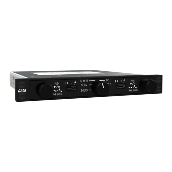
Control and volume of the Bluetooth audio playback can be adjusted using the BAA01’s built in front panel volume knobs. Figure 1: BAA01 Product Photo shows the front of the BAA01 and the front facing user controls that are applicable to each Bluetooth user. -
Page 7: Specifications
BAA01-001 Bluetooth Audio Accessory Installation and Operation Manual By using the mode selector knob in the center of the BAA01, the BAA01 can be placed into 5 different modes of operation: EMERG, NORM, BT MUTE, ISO 1, ISO 2. Using these modes, the audio from the Bluetooth users can be set to mute audio, isolate call audio from the audio controller or alter the audio routing to bypass the BAA01 circuitry. - Page 8 Current In: Note: If artificial sidetone is not available from the audio controller, utilize the BAA01 keyline (ART S/T Key) to produce sidetone back to the user’s headset. Only use (ART S/T Key) when speaking on a cellular call. 1.4.1.5 Output Signals:...
-
Page 9: Physical Specifications
MIL-DTL-5541 Type II Class 3. ≤ 2.5 mΩ from the rear connector metal housing Bonding Resistance: to any part of the BAA01 metal enclosure. Rev. 1.01 July 25, 2023 Page 4 of 37 ENG-FORM 804-0100.DOTX... -
Page 10: Environmental Parameter - Rtca/Do-160G
The Bluetooth module BM64C2 (BM64SPKS1MC2 Class 2) which is used in the BAA01 has received regulatory approval for the following: Notes: 1. The BAA01 currently only possess label markings from FCC and ISED on the product. 2. While the BM64C2 Bluetooth module has received regulatory approval for the following, the BAA01-001, has not been tested for the following regulatory approvals. -
Page 11: United States - Fcc
BAA01-001 Bluetooth Audio Accessory Installation and Operation Manual Korea/KCC: MSIP-CRM-mcp-BM64SPKS1MC2 Taiwan/NCC No: CCAN16LP0280T8 China/SRRC: CMIIT ID: 2016DJ2356 Brazil/ANATEL: 03822-18-08759 As per regulatory requirements, the statements in section 1.5.1- 1.5.8 have been included in this manual. 1.5.1 United States - FCC Contains FCC ID: A8TBM64S2 This device complies with Part 15 of the FCC Rules. -
Page 12: Canada - Ised
BAA01-001 Bluetooth Audio Accessory Installation and Operation Manual This equipment has been tested and found to comply with the limits for a Class B digital device, pursuant to part 15 of the FCC Rules. These limits are designed to provide reasonable protection against harmful interference in a residential installation. -
Page 13: Europe - Ce
BAA01-001 Bluetooth Audio Accessory Installation and Operation Manual 1.5.3 Europe - CE Certification Standards Article Safety EN 62368 3.1a Health EN 62311 Electro Magnetic Compatibility (EMC) EN 301 489-1 3.1b EN 301 489-17 Radio EN 300 328 Table 3: European Compliance 1.5.4... -
Page 14: Taiwan - Ncc
BAA01-001 Bluetooth Audio Accessory Installation and Operation Manual 1.5.6 Taiwan - NCC 注意 ! 依據 低功率電波輻射性電機管理 ? 法 第十二條 經型式認證合格之低功率射頻電機,非經許 可, 公司、商號或使用者均不得擅自變更頻率、加大功率或 變更原設計 之特性及功能。 第十四條 低功率射頻電機之使用不得影響飛航安全及 干擾合法通信; 經發現有干擾現象時,應立即停用,並改善至無干擾時 方得繼續使用。 前項合法通信,指依電信規定作業之無線電信。 低功率射頻電機須忍受合法通信或工業、科學及醫療用 電波輻射性 電機設備之干擾。 1.5.7 China - SRRC This device contains SRRC approved Radio module CMIIT ID 2016DJ2356 1.5.8... -
Page 15: Product Limitations
The use of cellular telephones while this aircraft is on the ground is subject to FAA regulations.” b) Maximum recommended cable length between BAA01 rear charging pins and connected chargeable device is 4.9 ft [1.5 m]. c) Maximum recommended cable length between BAA01 front panel charging ports and connected chargeable device is 3.3 ft [1.0 m]. -
Page 16: Section 2.0 Installation
These installation cases for section 2.3.1 and 2.3.2. are shown in the interconnect drawing at the end of this section. The behaviour of the BAA01 listed in this section is applicable when the BAA01 is in the Normal mode of operation. For further information specifying the operation of the BAA01 in different modes of operation, reference Section 3.3 Modes of Operation. -
Page 17: Baa01 In-Line Between The Headset And Audio Controller
2.3.1 BAA01 In-Line between the Headset and Audio Controller This use case is best suited to be able to select the BAA01 audio directly via the BAA01 while maintaining headset audio with the audio controller. In this configuration the BAA01 controls the summed audio of the audio controller and the connected Bluetooth device. -
Page 18: Baa01 Installation In A Transceiver Position Of The Audio Controller
The following statements apply when the BAA01 is installed in this configuration: a) Bluetooth audio is routed to the audio controller. b) The BAA01 must have a designated position on the audio controller’s selector for each Bluetooth user. c) Cellular calls from the connected smart device can be made and accepted. -
Page 19: Baa01 Multi-Unit Installation
When three or more Bluetooth users are required in an aircraft, it is possible to utilize the in-line between headset and audio controller interface for as many headsets as the audio controller can support. Figure 4: Multiple BAA01 to Audio Controller shows the installation configuration where cockpit and cabin headphone users are separated by using dedicated BAA01 devices. -
Page 20: Warranty
BAA01-001 Bluetooth Audio Accessory Installation and Operation Manual Warranty Please refer to the standard product warranty conditions available on our website, www.aem-corp.com Installation Procedure 2.5.1 Warnings WARNING: High volume settings can cause hearing damage. Set the headset volume control to the minimum volume setting prior to conducting tests, and slowly increase the headset volume to a comfortable listening level. -
Page 21: Pre-Installation Checks
11-66 through 11-69. 2.5.4 Pre-Installation Checks Do not connect the BAA01 to the wiring harness until the following conditions are met. Referencing the Interconnect drawing in Section 2.10 Installation Drawings, check the following: a) Check P100 pins 20 or 42 for specific lighting bus voltage relative to lights ground P100 pin 19 or 41. -
Page 22: Post-Installation Checks
Adjustments and Connections The BAA01 is shipped from the factory with all internal adjustments set to the normal audio levels. Some audio levels can be adjusted using the maintenance mode. Further information exists in section 3.5 Maintenance Mode. -
Page 23: Airworthiness Approval
Instructions for Continued Airworthiness Maintenance of the BAA01 is ‘on condition’ only. Periodic maintenance of this product is not required. The following sample Instructions for Continued Airworthiness (ICA) provides assistance in preparing ICA for the Anodyne Electronics Manufacturing Corp BAA01-001 unit installation as part of a Type Certificate (TC) or Supplemental Type Certificate (STC) project to comply with CAR STD (AWM) 523/527/525/529.1529 or... - Page 24 Make, Model and Serial Number] Content, Scope, Purpose and Arrangement: This document identifies the Instructions for Continued Airworthiness for an Anodyne Electronics Manufacturing Corp BAA01-001 installed in an [aircraft make and model]. Applicability: Applies to an Anodyne Electronics Manufacturing Corp BAA01-001 installed in an [aircraft make and model].
-
Page 25: Installation Drawings
BAA01-001 Bluetooth Audio Accessory Installation and Operation Manual Section Item Description Removal and Refer to Section 2 of this manual - the BAA01-001 Replacement Installation and Operating Manual. If the unit is removed Information and reinstalled, a functional check of the equipment should be conducted. - Page 26 REVISIONS DESCRIPTION DATE AA01-001 INSTALLATION NOTES OTES: ALL WIRES SHOULD BE 24 AWG U LESS OTHERWISE SPECIFIED. ALL U SHIELDED WIRE SHALL BE SELECTED I ACCORDA CE WITH AC43.13-1B CHA GE 1, PARAGRAPHS 11-76 THROUGH 11-78. WIRE TYPES SHOULD BE TO MIL-W-22759 AS SPECIFIED I AC43.13-1B CHA GE 1, PARAGRAPHS 11-85, 11-86 A D LISTED I TABLE 11-11.
- Page 27 BAA01-001 J100 62 CONTACT FEMALE DSUB MATING CONNECTOR 22 AWG 28V WR +28VDC WR 22 AWG WR GND 22 AWG LIGHTS 28V 20 +28VDC LIGHTS LIGHTS 5V 42 +5VDC LIGHTS RESERVED 51 ART S/T KEY 1 48 STEREO HE DSET J CK 1...
- Page 28 BAA01-001 J100 62 CONTACT FEMALE DSUB MATING CONNECTOR ART S/T KEY 2 36 STEREO HE DSET J CK 2 IC HI MIC IN HI 2 53 MIC IN LO 2 52 MIC LO PHONES RIGHT R HONES OUT HI 2...
- Page 29 BAA01-001 J100 62 CONTACT FEMALE DSUB MATING CONNECTOR MONO HE DSET J CK 1 IC HI MIC IN HI 1 8 MIC LO MIC IN LO 1 7 PHONES HI R HONES OUT HI 1 4 L HONES OUT HI 1 5...
- Page 30 BAA01-001 J100 62 CONTACT FEMALE DSUB MATING CONNECTOR UDIO CONTROLLER TX IC HI MIC IN HI 1 8 TX MIC LO MIC IN LO 1 7 RX HI R HONES OUT HI 1 4 L HONES OUT HI 1 5...
- Page 31 REVISIONS DESCRIPTION DATE 2 PIN HIGH DENSITY FEMALE DMIN MATING CONNECTOR 9 20 43 44 45 46 56 57 60 6 VIEW IS FROM REAR OF AIRFRAME CONNECTOR 27-Jul-2023 27-Jul-2023...
- Page 32 Jan 13, 2022 13-Jan-22...
-
Page 33: Section 3.0 Operation
BAA01 will play a message stating “Device connected”. The device is now ready for use. Note: Each BAA01 Bluetooth user can have up to 4 listed Bluetooth devices. If this number is exceeded, previously paired devices will be forgotten. The paired... -
Page 34: Bluetooth Troubleshooting
BAA01. g) If it is determined the BAA01 requires servicing, the BAA01 is to be left in EMERG mode (using the mode selector knob) until a loaner unit is supplied for removal. -
Page 35: Virtual Assistant Operation (Siri, Google, Alexa, Etc
3.2.3 Virtual Assistant Operation (Siri, Google, Alexa, etc..) The BAA01 is compatible with most major virtual assistants. The virtual assistant can easily be accessed while connected to a smart device by double pressing the volume knob of the desired Bluetooth user. Once pressed, the virtual assistant will automatically begin listening through the headset microphone. -
Page 36: Emergency Mode (Emerg)
The Emergency mode can be manually accessed by setting the mode selector knob to EMERG or automatically if Emergency Aircraft Voltage levels are detected by the BAA01. If the mode selector knob is deselected from EMERG or normal power is restored, the BAA01 will automatically restore itself to the last mode of operation. -
Page 37: Normal Mode (Norm)
3.3.2 Normal Mode (NORM) Normal mode is the standard operating mode for the BAA01. In this mode the audio of the connected Bluetooth device and the audio controller can be heard simultaneously. Figure 7: Normal Audio Routing shows the routing of the audio path during the Normal mode of operation. -
Page 38: Bluetooth Mute (Bt Mute)
BAA01-001 Bluetooth Audio Accessory Installation and Operation Manual 3.3.3 Bluetooth Mute (BT MUTE) Bluetooth Mute mode is used to isolate the audio controller and the users from the smart device. In this mode only audio from the audio controller can be heard on the user one and user two headset. -
Page 39: Cellular Call Isolate (Iso)
This results in the ART S/T Key not having to be triggered to hear sidetone. The BAA01 has two ISO modes that can be selected by the mode selector knob. These modes are identical in function except for the Bluetooth user to which it is applied. -
Page 40: Controls And Indicators
Each Bluetooth user has a dedicated volume knob. The push button is multifunctional with unique functions that vary based on the operating mode of the BAA01. Table 4 - Table 6 list the different functions of the volume knob in each mode of operation. - Page 41 BAA01-001 Bluetooth Audio Accessory Installation and Operation Manual BAA01 Normal Mode Volume Knob Action Annunciator BAA01 Response Action Colour No Bluetooth Pair - Idle Green Single Press Momentary Connect to last paired device Double Press Momentary Cancel connection attempt to last paired...
- Page 42 BAA01-001 Bluetooth Audio Accessory Installation and Operation Manual BAA01 Bluetooth Mute Mode Volume Knob Action Annunciator BAA01 Response Action Colour No Bluetooth Pair - IDLE Green Long Press Momentary Enter/Exit Non-connectable Mode All Bluetooth connections are disconnected in this mode.
- Page 43 BAA01-001 Bluetooth Audio Accessory Installation and Operation Manual BAA01 Bluetooth Call Isolate Mode Volume Knob Action Annunciator BAA01 Response Action Colour No Bluetooth Pair – IDLE Green Single Press Momentary Connect to last Paired Device Double Press Momentary Cancel connection attempt to last paired...
-
Page 44: Multicolour Led Annunciator
3.4.2 Multicolour LED Annunciator The front panel LED annunciators provides multicolour status indication of the BAA01 functions and state. Each Bluetooth user has an individually dedicated annunciator. Figure 11: Multicolour LED Annunciator shows a closeup view of the front facing annunciator. -
Page 45: Audible Annunciations
BAA01-001 Bluetooth Audio Accessory Installation and Operation Manual 3.4.3 Audible Annunciations The BAA01 provides audible feedback to the user by using the audible annunciations shown in Table 8. Action Audible Annunciation Message: “Bluetooth ON” Bluetooth Enabled Message: “Pairing Mode Enabled”... - Page 46 BAA01-001 Bluetooth Audio Accessory Installation and Operation Manual The audio parameters are individually adjustable for each Bluetooth user. The annunciator of the selected Bluetooth user will be flashing magenta when entering maintenance mode and can be switched between users by rotating the user one volume knob.
- Page 47 Mono Audio is Selected. Table 9: Maintenance Mode Annunciator Colour Definition The BAA01 will automatically disable the maintenance mode if no parameters are adjusted for 30 seconds. This is indicated by the annunciators briefly turning orange. To exit the maintenance mode the side accessible maintenance mode jumper must be removed, and the maintenance mode discrete input pin must not be grounded.
-
Page 48: Panel Backlighting & Annunciators
The two front USB-C and the rear USB pin set are only equipped to charge connected devices. No ability exists to transfer data or audio between the BAA01 and a connected device through USB. USB charging and Bluetooth operations are independent functions. -
Page 49: Rear Connector Charging Port
A USB 2.0 connector charging port pin-set is provided on the rear P100 connector. This charging port supports a maximum of 2.4A (12W) of charging current. The BAA01 provides an open collector discrete output (Pin 29 Rear USB Annunciator Output) to indicate when the rear USB connection has encountered a fault. The output is pulled to GND when a fault is present.
Need help?
Do you have a question about the BAA01 and is the answer not in the manual?
Questions and answers