Advertisement
Quick Links
VC6- - - - OPM
VC6
VC6
VC6
OPM
OPM
OPM
User's Manual
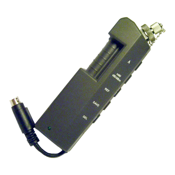
The V6C-OPM is an optical power meter
designed to attach to ViewConn
adds a new dimension to ViewConn's
capabilities, making ViewConn a cost-
effective and user-friendly 3-in-1 device
for connector-endface inspection,
cleaning, and optical power testing.
Specifications
®
. It
Calibrated Wavelength
Power Range
Resolution
Uncertainty
Interchangeable Tips
Tone Detection
Display Type
Data Storage
Data Downloading Interface
Software Support
Dimension
Weight
Operating Temperature
Storage Temperature
Humidity (non-condensing)
Lightel
2210 Lind Ave. SW, Suite 100
Renton, WA 98057
(425)277-8000 www.lighteltech.com
Optical
Optical
Optical
Optical
850, 1300, 1310, 1490, 1550, 1625
-60 ~ +10
0.01
(0.1dB when < -55dBm)
±5
Universal 1.25mm and Universal 2.5mm
Individual FC, SC, ST, LC, E2K available
Features
Features
Features
Features
270, 1k, 2k
(for 850nm, power within –25 ~ 10dBm,
for all other WL, power within –35 ~ 10dBm)
mW / dBm / dB(REF)
999
USB2.0
Included
Mechanical & Environmental
Mechanical & Environmental
Mechanical & Environmental
Mechanical & Environmental
125 x 37 x 30
100
-10 ~ +50
-20 ~ + 70
0 ~ 90
Technologies, Inc.
Technologies, Inc.
Technologies, Inc.
Technologies, Inc.
VC6- - - - OPM
VC6
VC6
VC6
OPM
OPM
OPM
Unit
Unit
Unit
Unit
nm
dBm
dB
%
Hz
Count
mm
g
°C
°C
%
VC6-OPM /UM Rev. A
Advertisement

Summary of Contents for LIGHTEL Technologies VC6-OPM
- Page 1 -10 ~ +50 °C Storage Temperature -20 ~ + 70 °C Humidity (non-condensing) 0 ~ 90 Lightel Technologies, Inc. Technologies, Inc. Technologies, Inc. Technologies, Inc. 2210 Lind Ave. SW, Suite 100 Renton, WA 98057 (425)277-8000 www.lighteltech.com VC6-OPM /UM Rev. A...
-
Page 2: Operation
“EXT” position to use the power meter. The interchangeable universal 2.5mm and 1.25mm tips provided with the VC6-OPM will allow you to test both PC and APC connectors. (Special tips for individual types of connectors are Figure 1 also available as options.) - Page 3 During OPM operation, if you switch ViewConn to the “INT” setting, the display will automatically switch to a connector inspection mode showing connector video images instead of showing optical power readings (Figure 4). ViewConn allows easy and simple switching between the connector video inspection and the power monitoring functions.
-
Page 4: Button Functions
Button Functions VC6-OPM contains 5 buttons through which a number of parameter selections or function selections can be executed. (1) “ “ “ “ λ λ λ λ ” button ” button ” button – for selecting the operating wavelength ”... - Page 5 To return to an absolute power measurement mode, simply press the “mW/dB/dBm” button to select mW or dBm. Note: Even when VC6-OPM is powered off, it will remember the last reference setting. This reference setting will be in the memory when the VC6-OPM is turned on again.
- Page 6 The sequential number of each record is automatically assigned with every Save action up to a maximum of 999. If you have four stored 999 records, you will hear short beeps reminding you that the storage is full. You will need to delete all or some of the records in order to gain additional space (refer to “DEL”...
-
Page 7: Software Installation
III. Software Installation To download the saved data in your VC6-OPM to your computer, you need to install Lightel’s “DataView” driver and software on your computer. Before starting installation, connect the power meter to ViewConn and turn it on. The green power meter light should be on. - Page 8 Figure 12 Figure 11 (B) Software installation After installing the driver, click “setup” on the Lightel CD and again follow the prompts to complete the software installation (Figure 13 – 16). Figure 14 Figure 13 Figure 15 Figure 16...
- Page 9 Figure 17 Figure 18 To download data, the VC6-OPM must be powered (connected to ViewConn, with ViewConn turned on, and select switch in “EXT” position). The green light on the power meter should be on, and the power meter connected to your PC through your USB mini-B cable.
- Page 10 You can add a note to any data record (Figure 21). These notes will be included when you save the downloaded data as text files or as Excel files. Figure 21 Figure 22 Click on the menu item “Option”, to open a window to include additional information in the data report (Figure 22).
Need help?
Do you have a question about the VC6-OPM and is the answer not in the manual?
Questions and answers