
Related Manuals for Star Cooperation FlexCard PXIe3

Summary of Contents for Star Cooperation FlexCard PXIe3
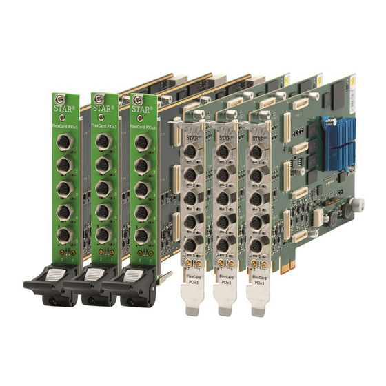
- Page 1 FlexCard PXIe3 and PCIe3 Instructions for Use NOTICE ESD (Electro Static Discharge) sensitive product. Refer to chapter 1.4 and follow the safety and handling instructions.
- Page 2 Contact Information STAR ELECTRONICS GmbH & Co. KG A Company of the STAR COOPERATION Group Jahnstraße 86 73037 Göppingen Phone: +49 (0)7031 6288-5656 Phone: +49 (0)7031 6288-5330 (Support) Sales: sales-ee@star-cooperation.com Support: support-ee@star-cooperation.com www.star-cooperation.com/ee-solutions Company Data STAR ELECTRONICS GmbH & Co. KG, registered offices: Göppingen, register court Ulm, HRA 721096 Partner liable to unlimited extent: STAR ELECTRONICS Verwaltungs-GmbH, registered offices: Göppingen, register...
- Page 3 EN 61000-6-4:2007 + A1:2011 (FlexCard PXIe3 only) EN 61326-1:2013 The FlexCard PXIe3 is a Class A product. Using the product in domestic environment may lead to electromagnetic disturbances. This product is compliant with the European Community Directive 2011/65/EC on the restriction of the use of certain hazardous substances in electrical and electronic equipment (RoHS).
- Page 4 EN 61326-1:2013 The FlexCard PXIe3 is designed, intended, and authorized for industrial use only. Using the product in domestic environment may lead to electromagnetic disturbances. This product is compliant with “the Restriction of the Use of Certain Hazardous Substances in Electrical and Electronic Equipment Regulations 2012”.
-
Page 5: Table Of Contents
Used Pictograms ..........................8 Safety and Handling Instructions ......................9 Meaning of Text Styles ........................10 Product Description ........................... 11 FlexCard PXIe3/PCIe3 at a glance ..................... 11 Accessory Parts ..........................11 Technical Data ............................ 13 Electrical Characteristics ........................13 Physical Characteristics ........................14 Environmental Conditions ........................ - Page 6 Firmware Update ..........................32 License Update ..........................32 Usage of the FlexCard PXIe3/PCIe3 ....................33 WebAdmin UI ............................. 33 Flash the FPGA ..........................34 Shipping, Maintenance and Disposal ....................35 Troubleshooting ..........................36 Ordering Information ......................... 37 FlexCard PXIe3/PCIe3 ........................37 Accessory Parts ..........................
-
Page 7: General
The use of the product by non-professionals is not permitted and strictly forbidden! Intended Use The FlexCard PXIe3/PCIe3 is a testing equipment. It was developed to test the communication behavior of automotive bus systems and Ethernet together with Electronics Control Units and sensors in a fully controlled testing and/or laboratory environment. -
Page 8: Used Pictograms
KG accepts no liability whatsoever for the correctness of any measurement results. WARNING The FlexCard PXIe3/PCIe3 is NOT designed, intended, or authorized and may NOT be used for or in connection with the following purposes and/or devices: - use as part of medical systems... -
Page 9: Safety And Handling Instructions
FlexCard PXIe3/PCIe3 has to be handled as described herein. Changes or modifications of the FlexCard PXIe3/PCIe3 is not allowed for safety and warranty reasons! STAR ELECTRONICS GmbH & Co. KG is not liable for any damages arising from non-observance of the product information. -
Page 10: Meaning Of Text Styles
NOTICE ESD (Electro Static Discharge) sensitive product STAR ELECTRONICS GmbH & Co. KG products lacking protective enclosures are subject to damage by ESD. Take proper ESD precautions to avoid performance degradation or loss of functionality! Unpack, handle or operate these products only in environments where sufficient precautionary measures have been taken in respect to ESD hazards. -
Page 11: Product Description
2 digital inputs or outputs (switchable between 5 V highspeed and 5/55 V high voltage resistance) Accessory Parts For usage of the FlexCard PXIe3/PCIe3, the following parts are necessary (not included in delivery): • for the FlexCard PXIe3 a PXIe Rack for the FlexCard PCIe3 a PC with PCIe interface •... - Page 12 NOTICE Use only accessories from STAR ELECTRONICS GmbH & Co. KG listed in chapter 8.2 with the FlexCard PXIe3/PCIe3 to ensure proper function and for warranty reasons! Other accessories without prior written consent of STAR ELECTRONICS GmbH & Co. KG must not be used.
-
Page 13: Technical Data
Technical Data Electrical Characteristics Min. Typ. Max. Supply current PXI system Operating 12V 150 mA 500 mA Operation 5.0Vaux 250 mA 500 mA Operation 3.3V 550 mA 1200 mA Supply current PCI system Operating 12V 150 mA 500 mA Operation 3.3V 750 mA 1200 mA Operation 3.3Vaux... -
Page 14: Physical Characteristics
172 mm * 125 mm * 18 mm including slot metal plate) Table 2: Physical characteristics Environmental Conditions NOTICE ATTENTION: An over temperature may damage the FlexCard PXIe3/PCIe3, if the temperature is higher than the allowed 70°C! Operating: -20°C – +70°C Temperature (FlexCard PXIe3) Non-operating: -40°C –... -
Page 15: Interfaces
Figure 1: Block diagram of FlexCard PXIe3 Figure 2: Block diagram of FlexCard PCIe3 Interfaces 3.5.1 Power FlexCard PXIe3 The FlexCard PXIe3 uses the 12 V, 3.3 V and 5.0 Vaux from the PXIe Rack. Created by STAR ELECTRONICS GmbH & Co. KG Date created... -
Page 16: Power Flexcard Pcie3
The respective UBAT supply pin of the bus driver ICs is connected to the permanent supplied voltage. 3.5.3 Digital In/Output (DIO) (FlexDevice Mode) The FlexCard PXIe3/PCIe3 can get or set digital signals like a FlexDevice-S or L in the DIO FlexDevice mode NOTICE A relay switch between the FlexCard mode and the FlexDevice mode. -
Page 17: Digital In/Output (Dio) (Flexcard Mode)
Table 4: DIO connector electrical specification in FlexDevice mode 3.5.4 Digital In/Output (DIO) (FlexCard Mode) For synchronization purposes in FlexCard mode, the FlexCard PXIe3/PCIe3 provides two 5V tolerant TTL- compatible trigger connectors (DIO[1] and DIO[2]) on the front panel. Created by STAR ELECTRONICS GmbH &... -
Page 18: Digital In/Output (Dio) Connector Und Leds
Between the two DIO connectors are two pairs of yellow and blue LEDs for visualization of user states or debugging purposes. For more information about the FlexCard PXIe3/PCIe3 DIO LEDs refer to the manual of the used application (e.g. FlexConfig RBS). -
Page 19: Bus Interfaces (Con 1 - 5)
T1. For other interfaces contact STAR ELECTRONICS GmbH & Co. KG. If necessary, it is possible to change the equipped FlexTiny III modules to different variants. Before changing FlexTiny III modules, unmount the FlexCard PXIe3/PCIe3 from the rack or PC to make sure that it is unpowered. - Page 20 Con 5 Figure 7: FlexTiny III interface 1 – 5 overview (the FlexCard PXIe3 is shown, the FlexCard PCIe3 is similarly) The size of the bus in the above figure depends on the used Tiny, 8 signal lines are available.
- Page 21 Tiny 3 Tiny 4 Tiny 5 Figure 8: FlexTiny III slots 1 – 5 on the FlexCard PXIe3/PCIe3 PCB (the PXIe3 is shown, the PCIe3 is similarly) NOTICE Check the correct direction from the FlexTiny module before inserting in the FlexTiny slot! Tiny 2 and 4 are turned 180°!
-
Page 22: Reset Button And User Leds
3.5.8 Reset Button and USER LEDs In case of malfunction or a required reset of the FlexCard PXIe3/PCIe3, it is possible to reset the FlexCard PXIe3/PCIe3 and load the Factory Image. A button is located at the front panel behind the small opening and must be pressed with a small nonmetallic tool for more than 4 seconds to initiate a reset. -
Page 23: Factory Image
Windows restart is required. 3.5.9 Factory Image If a reset is initiated (see chapter 3.5.8 Reset Button), the FlexCard PXIe3/PCIe3 will set the parameters and settings to default values and load the Factory Image. The changed parameters after loading the Factory Image can be found in Table 8. -
Page 24: Getting Started
FlexRay network. 4.1.2 Point-to-Point Bus Interface Connections When the FlexCard PXIe3/PCIe3 is connected to an existing network, the best way is a point-to-point connection, if necessary with an Active-Star. The point-to-point method offers the best signal integrity. Transmitted signals go from the transmitter to the Active-Star device, which forwards the signals to all other devices. -
Page 25: Stub Bus Interface Connections
4.1.4 Stub Bus Interface Connections The third method to connect the FlexCard PXIe3/PCIe3 to an existing network is the stub method. In this method, the devices are connected to a passive bus via stubs. Transmitted signals go from the transmitter via the stub to the bus and from the bus to the other devices. -
Page 26: Installation On Microsoft Windows Operating Systems
4.3.2 Installation on Microsoft Windows Operating Systems To install the FlexCard PXIe3/PCIe3 device driver and dynamic link library, please follow the steps below. The setup installs documentation in the form of pdf files to the local hard drive and creates shortcuts to them in the start menu. - Page 27 Step 3 Read the license agreement and if you accept the agreement, activate the option “I accept the terms…” and click the [Next] button to continue the installation. Otherwise click [Cancel] to abort the installation. Step 4 Select the installation folder for the FlexCard files.
-
Page 28: Uninstallation On Microsoft Windows Operating Systems
It is highly recommended to install the FlexCard Windows driver via setup.msi and not via INF-file! 4.3.3 Uninstallation on Microsoft Windows Operating Systems To uninstall FlexCard PXIe3/PCIe3 please follow these steps. Uninstall the FlexCard driver via the Windows Control Panel: Start->Settings->Control Panel... -
Page 29: Available Operating Modes
Flash the fpga image. Flash the s19 file. If the fpga distribution slot already has the correct fpga image type (FlexCard PXIe3: 0x1D0. FlexCard PCIe3: 0x1E0) the step "Flash the fpga image" can be skipped. The step "Flash the s19 file " cannot be skipped. - Page 30 4.5.1.2 Flash the fpga image 1. Start the tool FlexTFTP.exe. 2. Activate the checkbox "Auto Path". 3. Required fpga file: Hardware Type File Name FlexCard PXIe3 3-00940A01_distribution_0x01D0_x_x_x_x.fpga FlexCard PCIe3 3-00950A01_distribution_0x01E0_x_x_x_x.fpga 4. Drag the .fpga file and drop it on FlexTFTP =>...
-
Page 31: Change The Mode From Flexcard Mode To Flexdevice/Mixed Mode
The device is in the FlexDevice Mode now. FPGA images The FlexCard PXIe3/PCIe3 uses an FPGA image to access the automotive networks. The FPGA image defines what automotive network (FlexRay, CAN, …) is available at which connector. The operating mode decides how to get information about the used FPGA image. -
Page 32: Firmware Update
It is possible to mount less FlexTiny modules than described in the table. In this case the other FlexTiny modules can be used normally. Firmware Update In order to update the firmware of a FlexCard PXIe3/PCIe3, check the document [4] Firmware Update. A firmware update via FlexUpdate is not supported. License Update To update the FlexCard PXIe3/PCIe3 with a new license file, refer to the document [3] FlexUpdate User Manual. -
Page 33: Usage Of The Flexcard Pxie3/Pcie3
Usage of the FlexCard PXIe3/PCIe3 The following describes the usage of the FlexCard PXIe3/PCIe3 in a PXI rack or a PC. WebAdmin UI After installation of the FlexCard PXIe3/PCIe3 setup, a FlexCard symbol appears in the task bar. Figure 15: FlexCard task bar symbol Right-click on the symbol to display the menu. -
Page 34: Flash The Fpga
Figure 17: FlexCard PXIe3 WebAdmin UI (FlexCard PCIe3 is similar) The WebAdmin UI shows information about the connected FlexCard PXIe3/PCIe3 devices. The IP address of the device is listed. Use this IP address to access the device, e.g. in FlexConfig RBS or via PC-Hardware- Interface. -
Page 35: Shipping, Maintenance And Disposal
Shipping, Maintenance and Disposal Keep the package in which the FlexCard PXIe3/PCIe3 was shipped. Store and transport the FlexCard PXIe3/PCIe3 in a cool, dry, dark environment. Don’t store or transport it near sources of magnetic fields. NOTICE If you want to customize the components of the device, please contact STAR ELECTRONICS GmbH &... -
Page 36: Troubleshooting
Troubleshooting This chapter contains some frequently asked questions about the FlexCard PXIe3/PCIe3. The application running on the device does not respond. An application update via Effect PCIe local host is not possible. Solution You can try to reset your device. See chapter 3.5.9 for more details. -
Page 37: Ordering Information
Ordering Information FlexCard PXIe3/PCIe3 Product Description Ordering number FlexCard PXIe3 FlexCard PXIe3 hardware 3-V0940A01 FlexCard PCIe3 FlexCard PCIe3 hardware 3-V0950A01 Accessory Parts Product Description Ordering number Contact STAR FlexTiny III: FlexRay, CAN- Pluggable transceiver module with transceivers ELECTRONICS FD/HS, Ethernet and more GmbH &... -
Page 38: Appendix
Appendix Appendix A: Guideline for handling ESD sensitive Products Any tester, equipment, or tool used at any production step or for any manipulation of semi- conductor devices must have its shield connected to ground. The product itself and the carrier system of the product respectively must be placed on a conductive table top or covered by an antistatic surface (superficial resistivity equal to or higher than 0.5 MΩ/cm ), grounded through a ground cable (conductive cable from protected equipment... -
Page 39: List Of Tables
Figure 7: FlexTiny III interface 1 – 5 overview (the FlexCard PXIe3 is shown, the FlexCard PCIe3 is similarly) ..20 Figure 8: FlexTiny III slots 1 – 5 on the FlexCard PXIe3/PCIe3 PCB (the PXIe3 is shown, the PCIe3 is similarly) ... 21 Figure 9: FlexTiny fixation unit for the FlexCard PXIe3/PCIe3 ................ - Page 40 STAR ELECTRONICS GmbH & Co. KG A Company of the STAR COOPERATION Group Jahnstraße 86 73037 Göppingen Germany Phone: +49 (0) 7031 6288-5656 Info@star-cooperation.com www.star-cooperation.com/ee-solutions Created by STAR ELECTRONICS GmbH & Co. KG Date created 2022-02-15 Date modified 2022-02-15 Page 40 of 40...
Need help?
Do you have a question about the FlexCard PXIe3 and is the answer not in the manual?
Questions and answers