Advertisement
Quick Links
E.H. Wachs
600 Knightsbridge Parkway
Lincolnshire, IL 60069
www.ehwachs.com
MDSF Servo Electric Drive
E.H. Wachs Part No. 69-SERVO-MAN-01
Rev. A, July 2022
Copyright © 2022 E.H. Wachs. All rights reserved.
This manual may not be reproduced in whole or in part
without the written consent of E.H. Wachs.
User's Manual
Advertisement

Summary of Contents for E.H. Wachs MDSF
- Page 1 600 Knightsbridge Parkway Lincolnshire, IL 60069 www.ehwachs.com E.H. Wachs Part No. 69-SERVO-MAN-01 Rev. A, July 2022 Copyright © 2022 E.H. Wachs. All rights reserved. This manual may not be reproduced in whole or in part without the written consent of E.H. Wachs.
- Page 2 MDSF Servo Electric Drive 69-SERVO-MAN-01 E.H. Wachs Company...
-
Page 3: Purpose Of This Document
In This Document URPOSE OF OCUMENT URPOSE OF OCUMENT This document explains how to operate the E.H. Wachs MDSF servo electric drive. It describes the equipment com- QUIPMENT ESCRIPTION ponents and operating features, and includes a reference of ETUP AND ONNECTIONS error codes and troubleshooting. - Page 4 Read and follow all safety guidelines and instructions in the manual for your MDSF or EP 424 machine. Part No. 69-SERVO-MAN-01, Rev. A E.H. Wachs...
-
Page 5: Equipment Description
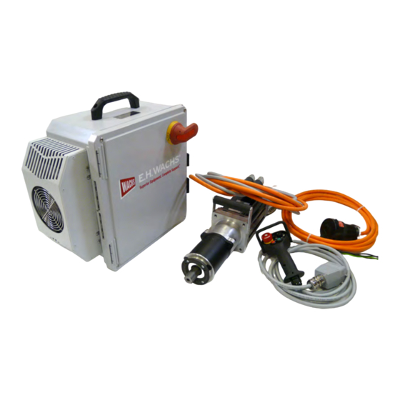
• power supply cabinet with on/off switch and electronic error code display panel • electric drive motor assembly with adapter for mounting to MDSF pinion housing • control pendant with start/stop, speed control, and emer- gency stop • power cable •... -
Page 6: Specifications
MDSF Servo Electric Drive Power Feedback Control Power source in cable to pendant cable to cable drive motor cable drive motor Figure 1-2. The drive system is provided in a custom storage/shipping case. Keep all components stored in the case when not in use. - Page 7 Installing the Motor on the MDSF Mount and position the MDSF on the pipe according to the instructions in the MDSF user’s manual. Mount the motor to the MDSF pinion assembly. Use a NOTE lifting device if necessary; the drive motor assembly has a lift handle.
- Page 8 MDSF Servo Electric Drive Connecting the Cables and Using the Control Cabinet A power cable for the appropriate electrical service is NOTE provided with the control cabinet. Connect it to the back of the control cabinet. The cable is supplied from the factory without a wall •...
- Page 9 When not operating the drive, push in the Emergency Stop button to prevent accidentally engaging the motor. To re-enable operation, pull out the Emergency Stop button, then press the Reset button. E.H. Wachs Part No. 69-SERVO-MAN-01, Rev. A...
-
Page 10: Operating The Drive
MDSF Servo Electric Drive Speed control —turn dial to adjust speed Emergency Stop —push to stop —pull to release Push Start to start Push Reset after motor while hold- releasing Emer- ing trigger gency Stop Figure 1-6. Use the control pendant to operate the drive. - Page 11 • pendant (gray) If necessary, install the appropriate power plug to the power source cable. Check that the cutting machine (MDSF or EP 424) is ready for operation, and that the drive assembly is cor- rectly mounted to the machine.
-
Page 12: Maintenance
MDSF Servo Electric Drive Turn the speed dial clockwise to increase the speed to the desired speed. As the machine operates, continue holding the trigger NOTE and adjust the speed as necessary using the speed dial. Release the trigger to stop the machine. -
Page 13: Error Codes
The LED display on top of the control cabinet displays error codes when there is an error condition. Appendix A lists and describes the error codes. Figure 1-10. The LCD screen on top of the control cabinet displays error codes during operation. E.H. Wachs Part No. 69-SERVO-MAN-01, Rev. A... - Page 14 MDSF Servo Electric Drive A: E PPENDIX RROR EFERENCE Part No. 69-SERVO-MAN-01, Rev. A E.H. Wachs...
- Page 15 Decimal Error Name Error Reaction Description Reduce motor load (less current, more standstill phases of the drive, lower clock time, lower accelerations), check thermal time constant Effective motor Reaction 2: Downramp / and nominal or reference current of the motor. Check motor 2311 8977 current monitor...
- Page 16 Reduce feedback energy (smaller deceleration), allow for more C3 PSUP: DC bus discharge time (reduce cycle time) or connect bus circuits of several Reaction 2: Downramp / 2381 9089 current offset too drives (low resistance!). Update in the C3M network with Firmware apply brake / de-energize..
- Page 17 Reduce motor utilization (Effective cycle). Current ripple may lead to motor heating due to a switching frequency set too low (increase switching frequency). If the motor is to be operated without temperature monitoring, you can deactivate the monitoring in the motor manager. Reaction 5: Switch-off of the Is the motor temperature sensor (correctly) connected and AC voltage supply...
- Page 18 Check digital outputs (X12 (pin 2, 3, 4, 5) and/or X22 (for additional Reaction 2: Downramp / 5233 21043 Sensor error In2 option M12 or M10)) for short circuit (max. 100 mA and 50nF apply brake / de-energize.. capacitive load per output). Reaction 2: Downramp / 5234 21044...
- Page 19 Reaction 5: Switch-off of the Error in the STO current immediately (without 5493 21651 safety function ramp), application of the brake T30/T40: Reduce number of instructions in the IEC 500us task, avoid commands issued at the same time to several profile generators (C3F: main axis/auxiliary axis or virtual master - C3S, M, H: triggering motion function / control virtual master and/or control of superimposed movements).
- Page 20 Reduce motor load (less current, more standstill phases of the drive, lower clock time, lower accelerations), check thermal time constant and nominal or reference current of the motor. Check motor dimensioning and replace motor by an adequately dimensioned IEC61131-3 Cycle Reaction 2: Downramp / 6281 25217...
- Page 21 If the software end limits are exceeded: Check set value default, end limits and referencing, bring axis back into permissible range. Invalid target position: Limit target position to the permissible travel range. In order to avoid the error message (not recommended in general, Reaction 1: Downramp actual but absolutely necessary in endless applications with reset distance) 6310...
- Page 22 Check feedback cable or feedback. EMC problems/very long motor cable? Is the resolver type used suitable for operation with Reaction 5: Switch-off of the Compax3 (transformation ratio)? If needs be, adapt (reduce) current immediately (without 7303 29443 Resolver 1 damaged excitation voltage (O280.5 - Resolver_ExcitationLevel) or software ramp), application of the gain factor (O280.3 Resolver_LevelAdaption).
- Page 23 Following error Reaction 2: Downramp / Check feedback wiring, check EMC, exchange feedback, perform 7322 29474 auxiliary axis apply brake / de-energize.. Homing again, deactivate use of the feedback memory. Target or actual Reaction 2: Downramp / 7323 29475 position exceeds Exchange feedback device.
- Page 24 Malfunction (motion caused by external source) of the motor during automatic commutation, starting current too great, incorrect parameter for commutation direction (use MotorManager to Reaction 5: Switch-off of the determine the values). Check feedback resolution (per pitch) and/or Resolver output level current immediately (without number of feedback or motor poles.
- Page 25 Reaction 5: Switch-off of the Hall commutation: current immediately (without Check feedback and feedback cable or increase upper limit value 73A0 29600 Invalid combination ramp), application of the (Obj287.11) if needs be. of hall signals brake Hall commutation: Reaction 2: Downramp / 73A1 29601 Invalid correction...
- Page 26 Feedback 1 SSI/Start- Reaction 2: Downramp / 73C2 29634 Stop: Value below as 7483 but with coupling segment apply brake / de-energize.. lower limit Verify configuration of the master channel (normalization), verify master segment distance and/or factor (too small?). Feedback 1 SSI/Start- Reaction 2: Downramp / The cause of the error might be a large master position step with 73C3...
- Page 27 Cam generator: cam Reaction 2: Downramp / 7485 29829 data coupling Wiring, terminal connector, check baud rate. apply brake / de-energize.. segment error Reestablish bus connection. The hardware may be defective. Cam generator: With CANopen (and high bus load), object 0x100D (life time factor) Reaction 2: Downramp / 7486 29830...
- Page 28 Create the prerequisites for the command: Setting the Master (Cmd 2,3) only if "global enable" (O3020.4) is not placed. Prepare coupling by change-over (Cmd 4, C3_CamIn,C3_CamOut) only if coupling / decoupling is not taking place at the same time. Prepare quadratic coupling (Cmd 5,7, C3_CamIn) only if coupling is not taking place at the same time and if the Master has already been set.
- Page 29 Reaction 1: Downramp actual Define or check active signal source for CAM. Select valid source for 8130 33072 FBI Timeout speed; remain in position switching or configure source to which you wish to switch control state. (C3_MasterControl). Reaction 1: Downramp actual 8181 33153 Invalid velocity...
- Page 30 The problem can occur with old firmware (R08 (before V04.05.07) or older) if during already active cyclic fieldbus mapping the CamCommand: mapped obect list is modified. -> in this case please update Reaction 2: Downramp / 8198 33176 invalid delta value for Compax3 firmware.
- Page 31 PowerOn (or state Reaction 2: Downramp / 8702 34562 'Switched On') not apply brake / de-energize.. allowed Switch-off of the current immediately (without ramp), Exception 00 DSP- FE00 65024 application of the brake, System output error number, system restart (software-reset). Switch-off of the current immediately (without ramp), Exception 00 DSP-...
- Page 32 Version conflict: Reaction 1: Downramp actual FF05 65285 Object data in the speed; remain in position flash are invalid control state. No object for process Reaction 1: Downramp actual FF06 65286 data; object cannot speed; remain in position be mapped control state.
- Page 33 Reaction 1: Downramp actual Flash sector delete FF20 65312 speed; remain in position failed control state. Reaction 1: Downramp actual Program flash cell FF21 65313 speed; remain in position failed control state. Reaction 1: Downramp actual Checksum error of FF22 65314 speed;...
- Page 34 Check feedback cable for EMC conform wiring (correct screening), Reaction 1: Downramp actual reduce EMC emissions in the environment (is the motor screened, is FF47 65351 Device type dif speed; remain in position the system correctly grounded etc.), reduce line length. Select a control state.
- Page 35 EnDat: Internal alarm Reaction 2: Downramp / FF72 65394 Exchange feedback. "position error" apply brake / de-energize.. EnDat: Internal alarm Reaction 2: Downramp / FF73 65395 Exchange feedback. "overvoltage" apply brake / de-energize.. EnDat: Internal alarm Reaction 2: Downramp / FF74 65396 Exchange feedback.
- Page 36 EnDat: Reaction 1: Downramp actual FF98 65432 Acknowledgement speed; remain in position Exchange feedback. error control state. Reaction 2: Downramp / FF99 65433 EnDat: Error type B Exchange feedback. apply brake / de-energize.. EnDat: invalid Reaction 2: Downramp / FF9A 65434 Exchange feedback.
- Page 37 Delete object 820.8 (if sync functionality is not required) or use firmware >=R08-3, delete object 2215.1 (if pressure/force control is Reaction 2: Downramp / FFA9 65449 SinCos® Parity error not required), reduce fast cycle calculation time load (if possible apply brake / de-energize.. disable speed observer, reduce HEDA mapping objects, ...
- Page 38 SinCos® size of the Reaction 2: Downramp / FFB0 65456 stated data field is apply brake / de-energize.. not variable SinCos® stated word Reaction 2: Downramp / FFB1 65457 address beyond data apply brake / de-energize.. field SinCos® access to Reaction 2: Downramp / FFB2 65458...
- Page 39 Check motor cable and connector Check motor (if insulation class of the motor is sufficient, look out for defective windings (e.g. due to overheat)) Check controller settings for instabilities: Current loop: Current controller bandwidth too large (>50%)-> current controller may be instable, saturation characteristic required, are the el.
- Page 40 Call up of a function Reaction 2: Downramp / FFE2 65506 module with invalid apply brake / de-energize.. parameters Wrong coupling/decoupling Reaction 2: Downramp / FFE3 65507 mode for C3_CamIn/- apply brake / de-energize.. C3 powerPLmC and Reaction 1: Downramp actual Compax3 software FFE4 65508...
- Page 41 Reaction 1: Downramp actual FFF8 65528 User error 8 speed; remain in position control state. Reaction 1: Downramp actual FFF9 65529 User error 9 speed; remain in position control state. Reaction 1: Downramp actual FFFA 65530 User error 10 speed; remain in position control state.
Need help?
Do you have a question about the MDSF and is the answer not in the manual?
Questions and answers