
Subscribe to Our Youtube Channel
Related Manuals for Symmetricom bc635PCI-V2


Summary of Contents for Symmetricom bc635PCI-V2
- Page 1 Time and Frequency Processor User’s Guide Revision A, July 2008 CD Part Number 098-00007-000...
-
Page 2: General
This warranty will survive inspection, acceptance, and payment by Buyer. Symmetricom does not warrant that the operation of such Products will be uninterrupted or error free. This warranty does not cover failures caused by acts of God, electrical or environmental conditions;... - Page 3 The physical media warranty does not apply to defects arising from misuse, theft, vandalism, fire, water, acts of God or other similar perils. Symmetricom will not be liable for any damages caused by the Buyer's failure to fulfill its responsibilities as stated above.
-
Page 4: Contact Information
User’s Guide – Time and frequency Processor Contact Information Symmetricom, Inc. Timing, Test & Measurement 3750 Westwind Blvd. Santa Rosa, CA 95403 Main: +1 (707) 528-1230 For Sales, Technical Support, and Return Materials Authorization, please see General Symmetricom Customer Assistance. -
Page 5: Preface
Preface Conventions The conventions used in this manual are: Note Tips and clarifications Warning: Actions to prevent equipment damage. Bold: Used to show messages, menu items, etc., that appear on a computer screen. For example, click on Submit Changes. Text: Used to indicate text you should enter with your keyboard, exactly as printed. -
Page 6: Table Of Contents
User’s Guide – Time and frequency Processor Table of Contents General ......................ii Symmetricom Customer Assistance ................. ii Copyright ........................ii Contact Information ....................iv Preface ........................v Conventions ......................v Errata ......................... v Table of Contents ..................... vi 1 Introduction ....................1 1.1 General Information .................... - Page 7 3.5 Programmable Periodic Output (PPO) .............. 20 3.6 DDS Output ....................... 20 3.6.1 Continuous mode..................20 3.6.2 Fractional mode ..................21 3.6.3 Divider Source.................... 21 3.6.4 Divider Mode ..................... 21 3.6.5 Multiplier Mode ..................22 3.7 Time Coincidence Strobe Output ..............23 3.8 PCI Interrupts ....................
- Page 8 User’s Guide – Time and frequency Processor 5.3.7 Command 0x16: Set Input Time Code Modulation Type ......41 5.3.8 Command 0x17: Set Propagation Delay Compensation ......41 5.3.9 Command 0x18: Request UTC Time Data (bc637PVI-V2 only) ....42 5.3.10 Command 0x19: Request TFP Data ............42 5.3.11 Command 0x1A: Software Reset .............
- Page 9 Appendix A: GPS Receiver Interface ............. 82 General ........................82 GPS Timing Mode (Mode 6) Characteristics ............82 Communicating With the GPS Receiver ..............82 Sending GPS Data Packets to the GPS Receiver ..........83 Receiving GPS Data Packets from the GPS Receiver ........83 Retrieve Packet from GPS Receiver (Command 0x31) ........
- Page 10 User’s Guide – Time and frequency Processor This page intentionally left blank...
-
Page 11: Introduction
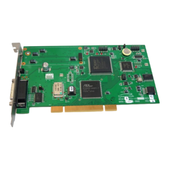
1 Introduction 1.1 General Information The Symmetricom model bc635PCI-V2 and bc637PCI-V2 Time and Frequency Processors (TFP) are high performance, 32-bit PCI plug-in cards used for precise time synchronization of the host computer over the PCI bus. These timing cards operate at 33 MHz and are compatible with PCI Local Bus Specification Revision 2.3. - Page 12 User’s Guide – Time and frequency Processor Figure 1-1: Model bc635PCI-V2 Synchronized Generator GPS Antenna bc637PCI V2 P/N 142-614-50 A: SMB Antenna Connector B: J1 Module I/O 15 pin „DS‟ Figure 1-2: Model bc637PCI-V2 (GPS option shown with GPS antenna) Note: These Time and Frequency Processors will be referred as “TFP”...
-
Page 13: Key Features
Chapter 1 Introduction 1.2 Key Features All modes of operation are supplemented by flywheel operation. If the synchronization source is lost, the TFP will continue to function at the last known reference rate. The following operational modes are supported, and are distinguished by the reference source. Mode Source of Synchronization Time Code - IRIG A, B, G, E, IEEE 1344, NASA 36, XR3 &... - Page 14 User’s Guide – Time and frequency Processor A DDS (a.k.a. frequency synthesizer) output may be selected in place of the periodic rate generator‟s output. The DDS offers a much wider frequency range than the Programmable Periodic. The DDS is discussed in more detail in Chapter 4.
-
Page 15: Definition Of Terms
The following is a glossary of key terms used in the discussion of timing operations: An expanded glossary of terms is available on-line at: http://www.symmetricom.com BCD: Binary Coded Decimal. Also called packed decimal, this is the representation of each digit of a decimal number by four-bit binary numbers. - Page 16 Time Compare. SW: Software. TCXO: Temperature Compensated Crystal Oscillator TFP: Time and Frequency Processor is the name given to the bc635PCI-V2 family of products. USNO: U.S. Naval Observatory, in Washington, D.C., where the atomic clock that serves as the official source of time for the United States is maintained.
-
Page 17: Performance Specifications Input
Designed Per PCI Local Bus Specification, Revision Single-Width 6.875” x 4.2” Size Auto Configurable IRQ Level 2 – 15 Interrupts Power (bc635PCI-V2) +5V @ 700 mA +12V @ 50 mA Power (bc637PCI-V2) +5V @ 800 mA +12V @ 50 mA Power (bc635PCI-V2-OCXO) +5V @ 800 mA (1.1A at start up) -
Page 18: Digital Inputs
User’s Guide – Time and frequency Processor 1.4.4 Digital Inputs 5V HCMOS,>2V high, < 0.8V, 270 Ω, zero latency, Event Capture Rising or Falling Edge Triggered, 20 nSmin. width, 250 nSmin. period 5V HCMOS, >2V high, < 0.8V low, 270 Ω, External 1 PPS Rising Edge On Time,20 nS minimum width 1.4.5 Digital Outputs... -
Page 19: Environmental Specifications
Chapter 1 Introduction 2. JP2 is the 1,5,10 MPPS or 10 MHz oscillator select switch. The factory configuration places the 2mm JP2 jumper on pins 1-2 which will allow for the software selection of 1, 5 or 10 MPPS for the output on J1 pin 13. - Page 20 User’s Guide – Time and frequency Processor Figure 1-3: Antenna parts The antenna is housed in completely waterproof packaging designed to withstand the elements. When the four UNC 4-40 screws are loosened, the antenna module detaches as shown below, exposing the TNC connector. Figure 1-4: Antenna with TNC connector Warning: Model bc637PCI-V2 supplies +5 VDC to the antenna.
- Page 21 Chapter 1 Introduction General Specifications for the Antenna –40°C to +85°C (–40°F to +185°F) Operating Temperature –40°C to +100° C (–40°F to +212°F) Storage Temperature Humidity 100% condensing Power 30 mA @ 5 V (supplied by card) Cable Specifications for the Antenna Cable Type RG-59 (Belden 9104) Length...
-
Page 22: Installation
User’s Guide – Time and frequency Processor 2 Installation 2.1 Installing the Card This section contains installation instructions for the Model bc635PCI-V2 and bc637PCI-V2 cards, and information regarding operating modes and the use of registers to configure the card. The Model bc637PCI-V2 has the additional feature of GPS mode that will automatically synchronize the card to UTC time. -
Page 23: Quick Initial Setup
Chapter 2 Installation operation and to become familiar with the equipment, the installation instructions are divided into “Quick Initial Setup” and “Permanent Installation” sections. We recommend that new users follow the “Quick Initial Setup” instructions first before proceeding to a permanent installation. 2.1.4 Quick Initial Setup Connect the antenna cable to the unit and to the antenna. -
Page 24: Choosing A Location
User’s Guide – Time and frequency Processor antenna mounting mast should be 2-inch (5.08-cm) water pipe or conduit. The mast must be rigid and able to withstand high winds without flexing. Guy wires may be used to stabilize a mast longer than 10 ft. (3.048 m). 2.1.6 Choosing a Location The antenna should be located with an unobstructed clear view of the sky from horizon to horizon for optimum tracking conditions. -
Page 25: Software Requirements And Installation
2 MB disk space 2.4 Installation Under Windows 2000/XP 1. With the PC turned off, insert the Symmetricom bc635/637PCI-V2 Time and Frequency Processor (TFP) in an open PCI slot. 2. Boot the PC. Once running, Windows may prompt you to install newly found hardware. -
Page 26: Optional Windows Software Development Kit
The SDK is an easy-to-integrate and highly reliable alternative to writing lower-level code to address a card‟s memory registers directly. The function calls and device drivers in the SDK make interfacing to a Symmetricom PCI card straightforward, keeping software development focused on the end application. - Page 27 With the wide variety of machines and operating systems that support the PCI bus, it is not possible for Symmetricom to develop drivers for use in all of these environments. While the interface to the device is well defined in this manual, the instructions for enabling and accessing the device are beyond the scope of this manual.
-
Page 28: Functional Description
User’s Guide – Time and frequency Processor 3 Functional Description 3.1 General This chapter provides a description of the bc635/637PCI-V2 Time and Frequency Processor (TFP) timing functions. Everyone using the TFP should read this chapter. Several terms used in this chapter are defined in Chapter 1, Definition of Terms. -
Page 29: Mode 2 (External 1 Pps Mode)
Chapter 3 Functional Description 3.2.3 Mode 2 (External 1 PPS Mode) In External 1 PPS Mode, the TFP synchronizes its oscillator to a user- supplied 1 PPS signal. The user must set major time manually. The Major Time is selected via the dual-port RAM interface as described in Chapter 5, using command 11. -
Page 30: Programmable Periodic Output (Ppo)
User’s Guide – Time and frequency Processor time capture function may also be set up in a capture lockout mode, where only the first Event Input or Periodic/DDS signal will store the event time. Any subsequent Event Times will not be stored until the capture lockout is disabled. -
Page 31: Fractional Mode
Chapter 3 Functional Description 3.6.2 Fractional mode Fractional mode allows the DDS circuit to generate a non-integer frequency after first being synchronized to the card's on-time 1PPS signal. DDS fractional frequency example: Desired frequency: 10,491,426.56 Hz Desired frequency x 32 10,491,426.56 x 32 = 335,725,649.92 Hz Rounded to integer 335,725,650... -
Page 32: Multiplier Mode
User’s Guide – Time and frequency Processor Result = 2964998 3.6.5 Multiplier Mode The DDS circuit also includes a frequency multiplier that may be used. The multiplier‟s input is the DDS and the output is DDS times the multiplication factor. This circuit can multiply the DDS frequency by 1, 2, 3, 4, 6, 8, 10 or 16. Note that the DDS frequency must be high or low enough for use (depends on multiplication factor - see following table). -
Page 33: Time Coincidence Strobe Output
PPO edge has occurred (edge selected by EVSENSE) Time Coincident Strobe output rising edge has occurred One second epoch (1 PPS output) rising edge has occurred GPS data packet is available (bc635pci-v2 only) 3.9 Timing Outputs In addition to the Programmable Periodic Output and Time Coincidence Strobe, the TFP provides other useful timing outputs that are synchronized to the timing source. -
Page 34: Calibration Procedure
The user should determine which time code to use in their system, and then perform the calibration for that code. The user can consult Symmetricom if unsure of which code type is best for their application. -
Page 35: Field Upgrade Of Embedded Program
Chapter 3 Functional Description code. 3.12 Field Upgrade of Embedded Program The bc635/637PCI-V2 uses flash memory, which is upgraded using an embedded boot loader program. Field upgrades are performed using the card's serial port, which is accessed from the J2 DIN connector on the rear panel. - Page 36 User’s Guide – Time and frequency Processor been returned, Press <P>. Use File/Send file... a dialog box pops up to select the file that is to be sent (e.g. bc635-v2.sx). The file should begin transferring with a string of asterisks being sent back to the terminal screen until the file transfer is complete (approximately 408KB).
-
Page 37: Device Registers
Chapter 4 Device Registers 4 Device Registers 4.1 General The bc635/637PCI-V2 Time & Frequency Processor (TFP) is controlled by a combination of hardware device registers and a dual-port RAM interface. This chapter describes the TFP device registers. Chapter 5 describes the dual-port RAM interface. -
Page 38: Timereq
User’s Guide – Time and frequency Processor TFP Device Register Summary Offset Type Reset Label Description 0x00 See Note TIMEREQ Time Request (TIME0-1) 0x04 See Note EVENTREQ Event Request (EVENT0-1) 0x08 See Note UNLOCK Release Capture Lockout 0x0C Reserved 0x10 CONTROL Control Register 0x14... - Page 39 Chapter 4 Device Registers CONTROL Register Name Function LOCKEN EVENTx Capture Lockout Enable 0 = Disable Lockout 1 = Enable Lockout EVSOURCE EVENTx Time Capture Register Source Select 0 = Event Input 1 = Periodic/DDS (Select Active Edge With EVSENSE) Event Edge Select 0=Falling EVSENSE...
-
Page 40: Ack
User’s Guide – Time and frequency Processor Enabling the Lockout function via the LOCKEN bit allows only the first instance of the selected signal source to latch time in the EVENTx registers, locking out any subsequent events, external or PPO/DDS. Use the UNLOCK register (0x08) to re-arm the circuit. -
Page 41: Time0 - Time1
Chapter 4 Device Registers time is programmable from hours through microseconds in the decimal time format. When the time format is set to binary, only the 22 least significant bits of the major time are used (in addition to microseconds), this allows the user to program the Strobe to become activated up to 48 days beyond the current time. -
Page 42: Status Bits
User’s Guide – Time and frequency Processor Table 2. TFP Decimal Time Format Register Data Bits 31 - 28 27 - 24 23 - 20 19 - 16 15 - 8 7 - 0 TIME1_ Days (0-366) Bits 7-0 Hours (0 - 23) Min (0-59) Sec (0- EVENT1... -
Page 43: Status: Phase (Bit 25)
Chapter 4 Device Registers 4.4.3 STATUS: Phase (Bit 25) This bit indicates the synchronization accuracy of the TFP relative to the timing source. This bit is updated approximately once per second. When the TFP‟s oscillator is synchronized to less than 5 microseconds with AM time code mode as a reference and less than 2 microseconds in other modes, this bit is cleared. -
Page 44: Dual-Port Ram Interface
User’s Guide – Time and frequency Processor 5 Dual-Port RAM Interface 5.1 General The byte-wide dual-port RAM (DPRAM) interface provides a communications pathway between the user and the bc635/637PCI-V2 Time & Frequency Processor (TFP) micro-controller (MPU). The RAM size is 2Kx8. The ACK register is used in conjunction with the DPRAM to avoid data contention when a memory location is accessed simultaneously from both sides of the DPRAM. -
Page 45: Ack Bit 2
Chapter 5 Dual-Port RAM Interface 5.2.2 ACK Bit 2 Set by the TFP to indicate that a GPS packet is available in the DPRAM GPS Packet Area. The user can clear this bit by writing to the ACK register with bit two set, but cannot set this bit. - Page 46 User’s Guide – Time and frequency Processor a. Offset 102 (input packet base address) b. Value 14 (14 is the set periodic output command ID) c. select the WRITE button d. Offset 103 e. Value 1 (value of 1 here selects Synchronous Mode) f.
- Page 47 Chapter 5 Dual-Port RAM Interface DPRAM Command Summary Reset Command 0x10 Set TFP Timing Mode 0x11 Set Time Register Format (1 = binary, 0 = bcd) 0x12 Set Major Time 0x13 Set Year 0x14 Set Periodic Output 0x15 Set Input Time Code Format 0x16 Set Input Time Code Modulation 0x17...
-
Page 48: Command 0X10: Set Tfp Timing Mode
User’s Guide – Time and frequency Processor 0xF5 Request Hardware Fab Part Number 0xF6 Request TFP Model Identification 0xFE Request TFP Serial Number (Request only) RTC: Real Time Clock (Restored at Power-on) Non Volatile (Restored at Power-on) 5.3.1 Command 0x10: Set TFP Timing Mode This command selects the timing mode of the TFP. -
Page 49: Command 0X13: Set Year
Chapter 5 Dual-Port RAM Interface reference signal in time modes 0 and 6, and from the RTC in mode 3. If time mode 0 or 6 is used, any major time written by this command will be overwritten when the selected source is providing a valid time to the TFP. Byte Type Item... -
Page 50: Command 0X15: Set Input Time Code Format
User’s Guide – Time and frequency Processor Byte Type Item Value or Range UINT8 0x14 0 = Don‟t Sync To 1PPS UINT8 Sync Flag 1 = Sync To 1 PPS UINT16 Divider n 2 - 65535 UINT16 Divider n 2 - 65535 5.3.6 Command 0x15: Set Input Time Code Format This command selects the time code format for TFP Timing Mode “0”... -
Page 51: Command 0X16: Set Input Time Code Modulation Type
Chapter 5 Dual-Port RAM Interface codes. Note: that when Legacy TrueTime IRIG B is used, the bc635/637PCI-V2 will decode the “Lock” bit that is encoded in the Control Function area and will not lock to the incoming code if the this bit = 1. 5.3.7 Command 0x16: Set Input Time Code Modulation Type This command selects the time code modulation type format for TFP Timing Mode “0”... -
Page 52: Command 0X18: Request Utc Time Data (Bc637Pvi-V2 Only)
User’s Guide – Time and frequency Processor 5.3.9 Command 0x18: Request UTC Time Data (bc637PVI-V2 only) This command queries current GPS and UTC time information derived from the GPS receiver. This command must be used in conjunction with Command 0x19. Byte Type Item... -
Page 53: Command 0X1B: Set Time Code Output Format
Chapter 5 Dual-Port RAM Interface 5.3.12 Command 0x1B: Set Time Code Output Format This command allows the user to select the time code format that is generated by the TFP on J1. Note that this selection is restored at power-up from NV memory. -
Page 54: Command 0X1C: Set Generator Time Offset
User’s Guide – Time and frequency Processor IRIG Control Function (CF) Bits In the following tables, tq1 through tq4 are time quality bits. For time quality and unlock bits, "1" means active. For IRIG output codes A, B, E or G with CF bits, the following CF bits are encoded: Index Bit count name... -
Page 55: Command 0X1D: Set Local Time Offset
Chapter 5 Dual-Port RAM Interface 5.3.14 Command 0x1D: Set Local Time Offset This command adds/subtracts local time offset to the TFP time. This command affects the TFP time only; the generator time is not affected. (See Command 0x1C.) Byte Type Item Value or Range UINT8... -
Page 56: Command 0X22: Force Jamsync
User’s Guide – Time and frequency Processor automatically. The default is jamsync enabled. Byte Type Item Value or Range UINT8 0x21 0 = jamsync disabled UINT8 jamsync ctrl 1 = jamsync enabled 5.3.18 Command 0x22: Force Jamsync This command forces the TFP to perform a single jamsync operation and contains no data. -
Page 57: Command 0X27: Synchronize Rtc To External Time Data
Chapter 5 Dual-Port RAM Interface 0x20 = OCXO 5.3.21 Command 0x27: Synchronize RTC to External Time Data This command forces the TFP to synchronize the RTC time to the current time. Note that when the TFP is locked to a timing reference, the RTC is adjusted automatically. -
Page 58: Command 0X41: Ieee 1344 Daylight Saving And Local Time Flags
User’s Guide – Time and frequency Processor Byte Type Item Value or Range 0x40 UINT8 UINT8 Flag 0 or 1 Local Time Observe Flag: 0 = disable 1 = enable 5.3.27 Command 0x41: IEEE 1344 Daylight Saving and Local Time Flags This command queries the daylight saving and local time observed flag. -
Page 59: Command 0X45: Dds Divide Select
Chapter 5 Dual-Port RAM Interface Byte Type Item Value or Range UINT8 0x44 UINT8 Dis/En see below 0 = Disabled 1 = Enabled 5.3.30 Command 0x45: DDS Divide Select The DDS frequency synthesizer's divider can be used to divide the selected input down to generate lower or fractional frequencies. -
Page 60: Command 0X47: Dds Synchronization Mode Select
User’s Guide – Time and frequency Processor 0 = DDS 1 = Multiplier (DDS x multiplier) 2 = 100 MHz (100 MHz PLL) 5.3.32 Command 0x47: DDS Synchronization Mode Select The DDS frequency synthesizer's divider has 2 modes of operation, Fractional and Continuous. -
Page 61: Command 0X4A: Dds Tuning Word
Chapter 5 Dual-Port RAM Interface 0x6 = DDS x6, 5 - 23 0x8 = DDS x8, 5 - 19 0xa = DDS x10, 5 - 15 0x10 = DDS x16 5 - 10 Note that when using Multiplier Mode, the DDS resolution is reduced to 1/32 Hz x multiplication factor. -
Page 62: Command 0X4F: Pci Firmware Part Number (Request Only)
User’s Guide – Time and frequency Processor 5.3.35 Command 0x4F: PCI Firmware Part Number (request only) This command allows the user to request the TFP firmware revision number. Byte Type Item Value or Range UINT8 0x4f „P‟ UINT8 0x50 „C‟ UINT8 0x43 „I‟... -
Page 63: Command 0Xf5: Hardware Fab Part Number (Read Only)
Chapter 5 Dual-Port RAM Interface 5.3.37 Command 0xF5: Hardware Fab Part Number (read only) This command queries the hardware fab part number of the TFP. The number is an identification of the fab being used for this hardware. Use this command in conjunction with Command 0x19. -
Page 64: Inputs And Outputs
User’s Guide – Time and frequency Processor 6 Inputs and Outputs 6.1 General Table 3 shows the pin connections for J1. 6.1.1 Signal I/O Connector This connector is used for most of the I/O signals as defined in Table 3. Table 3: Signal I/O Connector Direction Signal... - Page 65 Chapter 6 Inputs and Outputs bc637PCI GPS Antenna A: Connector SMB Antenna Connector P/N 142-614-50 B: Connector J1 Module I/O 15 pin „DS‟ Figure 6-1: bc637PCI – V2 card (Shown here with GPS Interface) 6.1 General...
-
Page 66: Software Programs
System Clock Utility TrayTime are included with the bc635/637PCI-V2 module. When installing the bc635PCI-V2 SW from the supplied CD as described in Chapter 2, the installer will create a folder in „program files‟ titled „bc635PCI Demonstration Software‟ containing Bc635pcidemo, TrayTime, and bc635pciReadEvent. - Page 67 Chapter 7 Software Programs Figure 7-1: bc637PCI-V2 set to GPS mode Figure 7-2: bc635PCI-V2 set to Time Code mode 7.3 Bc635pcidemo Control Panel Program Menu Interface Figure 7-3: Bc635pcidemo Control Panel Program 7.2 Quickstart Guide to Operating Bc635pcidemo...
-
Page 68: File Menu
User’s Guide – Time and frequency Processor 7.3.1 File Menu The File menu group provides a few common functions associated with Windows applications. File > Open Device Bc635pcidemo.exe is designed to communicate with only one device at a time. Open Device allows the user to open and operate any of up to four installed bc635/637PCI-V2 devices. -
Page 69: Time Menu
Chapter 7 Software Programs 7.3.2 Time Menu The Time menu group, see Figure 10, provides access to functions that control how the bc635/637PCI-V2 card maintains time data. These functions allow the user to select where to obtain time data, whether or not to manipulate the time data and how to present the time data. - Page 70 User’s Guide – Time and frequency Processor Figure 7-6: Get Binary Time Time > Get Event Time The Get Event Time menu selection exercises the event capture registers of the device. The function is similar to Get Binary Time where 25 consecutive requests are made to the event register.
- Page 71 Chapter 7 Software Programs Figure 7-7: Set Time Time > Set Year The Set Year menu selection will set the year data without affecting the other time data. Many time code formats (including standard IRIG B) do not include year information in the data. The supported range is 1990 – 2036, as shown in Figure 7-8.
- Page 72 User’s Guide – Time and frequency Processor The Set Prop Delay menu selection allows the user to compensate for propagation delays introduced by the currently selected reference source. For example, when the unit is operating in Time code decoding mode, a long cable run may result in the input time code having a propagation delay.
- Page 73 Chapter 7 Software Programs Figure 7-11: Set Leap Event Time Time > Time Settings The Time Settings function allows the user to modify other timing operations. The UTC Corrections may be enabled or disabled. Enabling UTC Corrections commands the device to include any leap second corrections provided by the reference source and act on any leap event data that is present.
- Page 74 User’s Guide – Time and frequency Processor Time > Current Settings The Current Settings function provides a summary of all the time data relevant to the devices current settings. In addition to the programmable values, the values of some of the card‟s timing data are also presented as information points via the UTC Data button.
- Page 75 Chapter 7 Software Programs The Decode menu selection allows the user to select the format and modulation types associated with an input timing signal. See Figure 7-15. These values control how the device attempts to decode the input time code. These values may be set regardless of the mode but will only be used in time code decoding mode.
- Page 76 User’s Guide – Time and frequency Processor Time Code > Generate The Generate menu selection allows the user to select the time code format that will be generated by the bc635/637PCI-V2, see Figure 7-16. See Chapter 5, command 0x1B for supported time codes. Detailed performance specifications are outlined in Chapter 1.
-
Page 77: Signals Menu
Chapter 7 Software Programs Time code > Current Settings The Current Settings menu selection provides time code output data summary. Figure 7-18: Current Settings (Request Time Code data) 7.3.3 Signals Menu The Signals menu group, see Figures 7-19 thru 7-26. This menu group provides access to functions that control various hardware-timing signals. - Page 78 User’s Guide – Time and frequency Processor Signals > Heartbeat Figure 7-20: Heartbeat The Heartbeat function allows the user to command the bc635/637PCI-V2 to produce a clock signal at a specified frequency. The heartbeat signal, also referred to as a periodic pulse output (PPO), periodic or programmable periodic, may be either synchronous or asynchronous to the internal 1 PPS epoch in the bc635/637PCI-V2 device.
- Page 79 Chapter 7 Software Programs Signals > Strobe The Strobe function allows the user to command the bc635/637PCI-V2 to produce a hardware signal at a particular time, or at a particular point during a 1 second interval. When major/minor mode is selected, a hardware signal (1 uS pulse) will be produced when the internal time of the bc635/637PCI-V2 device matches the values entered for the major and minor strobe registers.
- Page 80 User’s Guide – Time and frequency Processor Figure 7-23: Set Event Controls Note: The capture rate is dependent on the rate that the Software extracts the event times which is dependent on the operating system and speed of the host computer. Signals >...
- Page 81 Chapter 7 Software Programs in detail in Chapter 4. Figure 7-25: Select Interrupt Sources Signals > Current Settings The Current Settings function provides a summary of all the signal data. In addition to the programmable values, other values may be presented as information points.
-
Page 82: Hardware Menu
User’s Guide – Time and frequency Processor 7.3.4 Hardware Menu See Figure 7-27. This group provides additional access to functions that control the oscillator and its associated disciplining circuits. These functions modify the actual oscillator control function used to slave the oscillator to the selected reference signal. - Page 83 Chapter 7 Software Programs Hardware > Sync RTC to Ext Time The Sync RTC to Ext Time function updates the RTC circuit time to the current time on the board. See Figure 7-29. The board contains a separate battery-backed Real Time Clock Circuit (RTC) that may be used to keep time while the device is powered down.
-
Page 84: Special Menu
User’s Guide – Time and frequency Processor 7.3.5 Special Menu The Special Menu group provides access to those functions that do not fit in any particular category. See Figure 7-31. Most of these functions are not used during normal operation. Figure 7-31: Special Menu Special >... - Page 85 Chapter 7 Software Programs Special > Board Reset The Board Reset function allows the user to reset the bc635/637PCI-V2 device. See Figure 7-33. This command is useful when starting a test or in the case that unexpected behavior is observed from the card. This function is not used during normal operation.
-
Page 86: Pci Menu
User’s Guide – Time and frequency Processor DP RAM DP RAM allows reading, writing hex offsets, and values to the dual port RAM. Figure 7-35: Dual Port RAM Packet Offset Displays the following packet information Figure 7-36: Packet Offset Debug Debug can be turned off or on. -
Page 87: System Clock Utility (Traytimecpp.exe)
7.4 System Clock Utility (Traytimecpp.exe) This utility is designed to operate under Microsoft Windows 2000/XP. This system tray utility will query the bc635PCI-V2 or the 637PCI-V2 card, and set the system clock on a periodic basis. Double click on the “TrayTimeCPP.exe”... -
Page 88: Installation
If the Current Status is: “Waiting for the board to acquire time,” then the time on the host computer has not synchronized to the bc635PCI-V2 time yet. If the status is: “Set Clock OK” or “Captured Board Time,” then the synchronizing process is taking effect. - Page 89 Chapter 7 Software Programs Figure 7-39: TrayTime main window OK: Minimizes the utility into the Windows System Tray. Quit: Exits the utility. About: Shows utility version number. Setup: Launches the Setup Windows. Sync Now: Commands the utility to capture time from the board and set the system‟s time.
- Page 90 User’s Guide – Time and frequency Processor Status Window Figure 7-40: Status Window Hardware Source: Shows the selected Hardware type used for time synchronization. Hardware Mode: Shows the selected Hardware mode. Current Status: Shows the current update status. If status is: “Waiting for the board to acquire time”...
- Page 91 Chapter 7 Software Programs Configuration Window Figure 7-41: Configuration Window Hardware Source: The TrayTime utility supports the listed 8- types of hardware sources. Mode Selection: The TrayTime utility supports setting the mode on the selected hardware. Note: “GPS Mode” is only available on GPS capable devices. Windows Service: Check this option to run the TrayTime utility as a Windows service.
-
Page 92: Appendix A: Gps Receiver Interface
User’s Guide – Time and frequency Processor Appendix A: GPS Receiver Interface General The most common difficulty encountered using GPS equipment is antenna position. The GPS antenna must be located in an area that has a clear view of the sky. The GPS signals cannot penetrate foliage or structures. A good antenna position will provide optimal timing performance. -
Page 93: Sending Gps Data Packets To The Gps Receiver
Chapter Appendix A: GPS Receiver Interface stuffing/unstuffing operations. The bc637PCI-V2 user should be concerned with the packet length, packet ID, and packet data bytes only. Sending GPS Data Packets to the GPS Receiver To send a GPS data packet to the receiver, use the DPRAM command “Send Packet to GPS Receiver”... - Page 94 Once the request has been sent, the bc635PCI-V2 sets ACK bit 0 to acknowledge the retrieve packet command. Later,...
-
Page 95: Manually Request Packet From Gps Receiver (Command 0X32)
ID of a packet sent by the receiver (response packet) and specifies the packet length, ID, and data for the packet to be sent to the receiver (request packet.) The bc635PCI-V2 sends the request packet to the receiver and transfers the response packet to the DPRAM GPS Packet Area when it arrives. -
Page 96: Position Fix Modes
User’s Guide – Time and frequency Processor As an example of this command, let‟s suppose the user wants to retrieve packet 0x5B (satellite ephemeris status) for satellite number six. The receiver sends packet 0x5B in response to packet 0x3B (request satellite ephemeris status.) Packet 0x3B specifies the PRN number for the satellite of interest, in this case, satellite number six. -
Page 97: Position Fix Mode 3 And 4
Chapter Appendix A: GPS Receiver Interface GPS packet 0x34 allows the satellite associated with mode one to be selected. This packet has one data byte that specifies the PRN of the desired satellite. If a data byte value of 0 is entered, then the sensor will always track the single satellite that has the highest elevation within the constellation in view. -
Page 98: Set I/O Options (Gps Packet 0X35)
User’s Guide – Time and frequency Processor Set I/O Options (GPS packet 0x35) Packet Data Item Value Packet ID 0x35 Position 0x03 Velocity 0x03 Timing 0x00 Auxiliary 0x00 To change any of the packet 0x35 options, keep the following in mind: The bc637PCI-V2 monitors position and velocity packets so the “position”... -
Page 99: Appendix B: Gps Software Program
Chapter Appendix B: GPS Software Program Appendix B: GPS Software Program General In addition to the Configuration and Demo Program (Bc635pcidemo.exe), and the System Clock Utility (TrayTime.exe), the bc637PCI-V2 includes a GPS demonstration program (bc637PCI GPS Demo). When installing the bc637PCI-V2 SW from the supplied CD, as described in Chapter 2, the installer will create a folder in „program files‟... -
Page 100: Quickstart Guide To Operating Bc637Pci Gps Demo
User’s Guide – Time and frequency Processor Quickstart Guide to Operating bc637PCI GPS Demo 1. Verify that the antenna is connected to the SMB connector on the rear of the card. See Chapter 2 for hardware installation details. 2. Click on the bc637PCI GPS Demo desktop icon to execute the program. The card will start counting using the RTC value, until lock is achieved. -
Page 101: Bc637Pci Gps Demo Control Panel Program Menu Interface
Chapter Appendix B: GPS Software Program bc637PCI GPS Demo Control Panel Program Menu Interface Figure B-3: File Menu File Menu The File menu group provides a few common functions associated with Windows applications. File > Open bc637PCI GPS Demo is designed to communicate with only one device at a time. - Page 102 User’s Guide – Time and frequency Processor File > Save This command allows the user to save the values to the GPS receiver located under “Save > Save variable”. For more information on the GPS variables, see Appendix A: GPS Receiver Interface. Figure B-5: File Save File >...
-
Page 103: Time Menu
Chapter Appendix B: GPS Software Program This command allows the user to close the device and exit the program. Time Menu The Time menu group, see Figure B-7, provides access to functions that control how the bc637PCI-V2 card maintains time data. These functions allow the user to select where to obtain time data, whether or not to manipulate the time data, and how to present the time data. - Page 104 User’s Guide – Time and frequency Processor Time > Set Board Time The Set Board Time menu selection will set the time on the bc637PCI-V2 device. The Set Board Time interface GUI displays the current time, years through seconds in a decimal format, see Figure B-8. The user may change any or all of these values and select the OK button.
-
Page 105: Status Menu
Chapter Appendix B: GPS Software Program Time > Receiver Time The Receiver Time menu selection will return time from the GPS receiver (see Figure B-10). This command requests current time via packet 0x21, and returns packet 0x41, as described in Appendix A: GPS Receiver Interface. Figure B-10: Set receiver - GPS Time Status Menu The Status menu group, see Figure B-11 through B-14, provides access to... - Page 106 User’s Guide – Time and frequency Processor Figure B-12: Request GPS Receiver Health Figure B-13: Request Satellites Signal Figure B-14: Request UTC Information...
-
Page 107: Mode Menu
Chapter Appendix B: GPS Software Program Mode Menu The Mode menu group, see Figure B-15 through B-18 provide access to the various functional modes of the bc637PCI-V2 and the GPS receiver. The Mode > Set Board Mode menu selection allows the user to change the operating mode of the installed bc637PCI-V2 card. - Page 108 User’s Guide – Time and frequency Processor Figure B-16: Mode Menu: Set Automatic Fix Mode Figure B-17: Set/Request GPS Receiver Position Fix Mode Figure B-18: Request Board Mode...
-
Page 109: Position Menu
Chapter Appendix B: GPS Software Program Position Menu The Position menu group, see Figure B-19 through B-23 provide access to position data from the GPS receiver. Both LLA and XYZ position formats are supported. These packets are addressed in more detail in Appendix A: GPS Receiver Interface, packets 0x2B, 0x31, 0x42, and 0x4A. - Page 110 User’s Guide – Time and frequency Processor Figure B-21: Set Accurate Position – XYZ Figure B-22: Request Position - LLA Figure B-23: Request Position - XYZ...
-
Page 111: Options Menu
Chapter Appendix B: GPS Software Program Options Menu The Options menu group, see Figures B-24 through B-28 provide access to set or request the input and output options for the GPS receiver. These commands are described in more detail in Appendix A: GPS Receiver Interface, packets 0x35, 0x43, and 0x56. - Page 112 User’s Guide – Time and frequency Processor Figure B-27: Request Velocity XYZ Figure B-28: Request Velocity ENU...
-
Page 113: Request Menu
Chapter Appendix B: GPS Software Program Request Menu The Request menu group, see Figures B-29 through B-32 provide access to data from the GPS receiver. These commands are described in more detail in Appendix A: GPS Receiver Interface, packets 0x40, 0x4C, and 0x4D. Figure B-29: Request Menu Request >... - Page 114 User’s Guide – Time and frequency Processor Request > Oscillator Offset This packet provides the receiver oscillator offset in Hertz at the carrier. The packet format is described in Appendix A: GPS Receiver Interface, packet 0x4D. Figure B-31: Request Oscillator Offset Request >...
-
Page 115: Send Menu
Chapter Appendix B: GPS Software Program Send Menu The Send menu group, see Figures B-33 through B-35, allows the user to set the 2-D altitude and receiver operating parameters on the GPS receiver. These commands are described in more detail in Appendix A: GPS Receiver Interface, packets 0x2A and 0x2C. - Page 116 User’s Guide – Time and frequency Processor Send > Operating Parameters This packet is used to optionally set the GPS receiver operating parameters, requesting the current values after they are set. See Appendix A: GPS Receiver Interface, packet 0x2C for more detail. Figure B-35: Send Set Operating Parameters...
-
Page 117: Reset Menu
Chapter Appendix B: GPS Software Program Reset Menu The Send menu group commands, see Figure B-36 through B-40, are used to reset various components on the PCI card and the GPS receiver. Figure B-36: Reset menu Reset > Board Reset This command will reset the bc637PCI-V2 card per the DPRAM command 0x1A, and is described in Chapter 5. - Page 118 User’s Guide – Time and frequency Processor Reset > Receiver Reset This command performs a GPS receiver software reset, which is equivalent to cycling power. The self-test function is performed as part of the reset operation. This command is described in more detail in Appendix A: GPS Receiver Interface, packet 0x25.
-
Page 119: Help Menu
Chapter Appendix B: GPS Software Program Help Menu The Help menu group provide access to data from the bc637PCI-V2 hardware and GPS receiver. Figure B-41: Help Menu Help > Board Firmware Version The Board Firmware Version command returns information from the bc637PCI-V2 firmware. - Page 120 User’s Guide – Time and frequency Processor Help > Receiver Firmware Version The Receiver Firmware Version returns firmware version information for the GPS receiver. The data format is covered in Appendix A: GPS Receiver Interface, packet 0x45. Figure B-43: Receiver Firmware Version Help >...
-
Page 121: List Of Hardware
Chapter Appendix B: GPS Software Program List of Hardware The GPS antenna equipment described in this manual consists of the following: One wide-range 5-12 VDC L1 antenna One 50 ft. length of Belden 9104 coaxial cable with BNC(m) and TNC(m) connectors SMB to BNC adaptor is included The Antenna Kit can be ordered with optional cable lengths and accessories. -
Page 122: Appendix C: What Is Different In The Bc635/637Pci-V2
User’s Guide – Time and frequency Processor Appendix C: What is different in the bc635/637PCI-V2? There is a difference in the PCI base address register mapping between the bc635PCI-U and the bc635/637PCI-V2 cards. Both the bc635PCI-U and the bc635/637PCI-V2 cards map both register and dpram into memory spaces. PCI bar mapping: bc635PCI-U bc635/637PCI-V2... -
Page 123: Additions To The Bc63Xpci-V2
Chapter Appendix C: What is different in the bc635/637PCI-V2? month at UTC midnight. BC635 application advanced/PCI Special Boot mode is not supported on the -v2 design. Although the user timing resolution of both cards is 100 nS, the -v2 card has an internal resolution of 5 nS (200 MHz clock locked to the 10 MHz oscillator). -
Page 124: Index
ACK Bit 2, 36 ACK Bit 7, 36 Additions to the bc63xPCI-v2, 114 Antenna Installation, 14 Antenna Location, 13 Antenna Specifications (bc637PCI-V2 only), 10 bc635PCI-V2, 2 bc637PCI-V2, 2 calibration factor, 25 Calibration Procedure, 25 card installation, 13 Choosing a Location, 15... - Page 125 Signal I/O Connector, 55 Signals Menu, 68 Software Programs, 57 Software Requirements and Installation, 16 Special Menu, 75 Symmetricom Customer Assistance, ii synchronized generator mode, 4 System Clock Utility, 78 TFP DPRAM Commands, 36 Time Capture, 20 Time Code Calibration, 24...
Need help?
Do you have a question about the bc635PCI-V2 and is the answer not in the manual?
Questions and answers