Table of Contents
Advertisement
Quick Links
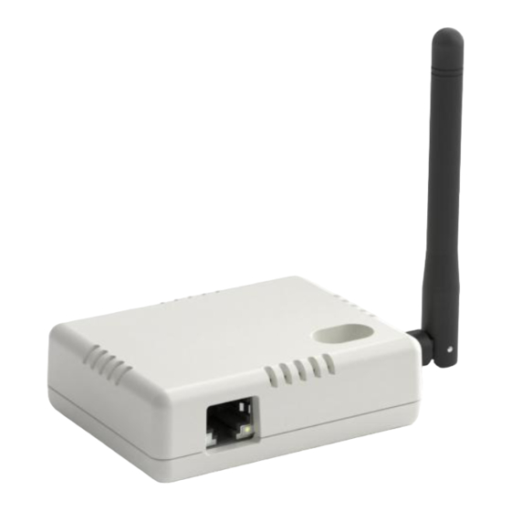
G1
GATEWAY
The MUONIO system is a network of
smart devices for heating/cooling and
ventilation applications that brings
comfort to your home.
The Gateway (G1) is the heart of the
MUONIO system. It incorporates all
of the relevant features required to
create, commission and operate a
smart heating/cooling and ventilation
system.
The Gateway is connected to the
Local Area Network (LAN) on one side
through an ethernet cable and on the
other side, it is wirelessly connected
to different MUONIO smart devices in
your home allowing you full control
of all your heating/cooling and
ventilation requirements.
USER MANUAL
Advertisement
Table of Contents

Summary of Contents for Muonio G1
- Page 1 The MUONIO system is a network of smart devices for heating/cooling and ventilation applications that brings comfort to your home. The Gateway (G1) is the heart of the MUONIO system. It incorporates all of the relevant features required to create, commission and operate a smart heating/cooling and ventilation system.
- Page 2 Introduction This manual describes how to understand and install G1 Gateway. This device is meant to work in combination with the MUONIO devices and it is not a stand-alone device. WARNING & INFORMATION SYMBOLS WARNING & INFORMATION SYMBOLS The addition of this symbol to a “Danger” or “Warning” safety label indicates that an electrical hazard exists which will result in personal injury if the instructions are not followed.
- Page 3 Introduction REPAIRS Repairs may be required if G1 Gateway device has been damaged in any way, for example, if the device has been exposed to water, rain, or moisture, if the product does not work normally or if the product has been dropped. If smoke, unusual noises, or smells are noticed, switch off the device immediately.
-
Page 4: How To Get Started
To create an account, click on SIGN UP when you open the APP (Figure 2). You will be prompted to enter your email and password (Figure 3). You will receive a confirmation email if done correctly. The MUONIO system does not ask you for any personal data. - Page 5 How to get started 3. CONNECT YOUR ACCOUNT TO A SPECIFIC GATEWAY To set up a new system and to connect it to your account you will first need to connect the Gateway (G1) to your local network. Connect one side of the ethernet cable (supplied with the device) to the gateway (Figure 4), connect the other side of the ethernet cable to any available port on your router, connect the external antenna to the gateway (figure 4), connect the power supply (supplied with the device) to the Gateway (Figure 4) and power up the device.
- Page 6 How to get started FIGURE 8. USERS INVITE FIGURE 7. MENU AFTER LOGIN Log in to your account and you will be able to see the particular GATEWAY connected to your account (make sure you have an internet connection). Go to the SETTINGS page to see the MAC address of the GATEWAY. It should be the same as one that you are connected to locally.
- Page 7 1) Make sure the G1 Gateway is properly connected to the local network and powered up. 2) Make sure the device you want to join the network is in the proximity of the G1 Gateway. 3) With the power to the device switched off, Insert the ID KEY into the device you want to add to the network.
- Page 8 How to get started Before and air quality sensor is added After an air quality sensor was added FIGURE 10. SENSORS ADDED TO THE NETWORK WILL AUTOMATICALLY SHOWN UP IN THE APP When a device is properly added to the network it will appear on the app within a few moments. In this example, the sensor added is shown on the HOME page but it will also appear on the SETTINGS page.
- Page 9 How to get started The SETTINGS page is the most important page for the installation phase. Here you will check how the network is set up / organized and how well the system is operating. TIPS: Changing data here without a full understanding of the system can potentially damage the system and result in undesirable operation.
- Page 10 How to get started On the SETTINGS page, click on any device added to the network and you will be brought to a new MENU. By clicking on the a relay board you will be directed to the RELAY menu (Figure 12). By clicking on any sensors you will be directed to the ZONE menu (Figure 13).
-
Page 11: Setting Up The Network
How to get started SETTING UP THE NETWORK Once the different devices have been added to the system, you need to organize/set up the devices on the network so they work as required for your particular system. More details about specific devices can be found in the USER MANUALS for those devices. However, the basics will be covered here. -
Page 12: Heating/Cooling Selection
How to get started HISTORICAL DATA WITHIN SETUP FIGURE 15. Hystorical data showing connection quality of the devices to the gateway At the bottom of the SETTINGS PAGE, it is possible to view the historical data in regards to the quality of the connection between the individual devices on the system and the GATEWAY. - Page 13 Software HOME PAGE The top right-hand side of the home page shows the ALARM button and the MENU button on the top left. By pressing the MENU button you get a list of options to choose from. By pressing the ALARM button you can check the current alarm status for the various devices connected.
- Page 14 Software explained ZONE SETINGS MENU EXPLAINED Current zone parameters. Depending on the type of sensor in the zone, it can read temperature/humidity and additionally air quality data if required. Heating settings OFF - The Zone is fully off but it will turn on if the ambient temperature drops OFF F below 4°C for frost protection.
- Page 15 Software explained HEATING/COOLING SETTINGS* Schedule ON/OFF - if you turn on schedule, the current mode of work will be set as per the schedule. If a schedule is not selected you will be able to manually select any of the 4 modes of work (Home, Away, Sleep, Off)and no further settings are considered.
- Page 16 Software explained HEATING/COOLING SCHEDULE Each day can have a separate schedule. There are default values inside that you can alter. Each day is divided into a maximum of 24 periods with a minimum duration of 1-hour. Each period can have one of the 4 modes of work (OFF, HOME, AWAY, SLEEP) selected.
- Page 17 Software explained DOMESTIC HOT WATER SCHEDULE FIGURE 19. DOMESTIC HOT WATER SCHEDULE The Domestic Hot Water schedule is similar to the regular heating schedule but only has two modes of work (AWAY and HOME). If AWAY is selected, the system will not produce domestic hot water during this period. FIGURE 20.
- Page 18 However, if the system is new, it has to be connected locally for the first time and can also be controlled locally if the internet is not available. The devices are wirelessly connected to the GATEWAY (G1). Depending on your system setup there could be different types of devices, that are being used for heating/cooling and/or ventilation.
-
Page 19: Troubleshooting
System explained TROUBLESHOOTING: Ethernet LEDs: Ethernet cable not connected to the router or is connected but the connection is not active: Ethernet LEDs are not blinking. GATEWAY LEDS (LEDs that you can see through air ventilation ports on the Gateway): DFCP fail: blink fast 6 times DNS fail: blink slow 4 times SOCKET fail: blink slow 3 times... - Page 20 Software setup ZONE 1 MAC ADDRESS _____________________________ NAME _______________________ ZONE 2 MAC ADDRESS _____________________________ NAME _______________________ ZONE 3 MAC ADDRESS _____________________________ NAME _______________________ ZONE 4 MAC ADDRESS _____________________________ NAME _______________________ ZONE ________ TYPE ________ MAC ADDRESS ______________________ NAME _______________________ ZONE ________ TYPE ________ MAC ADDRESS ______________________ NAME _______________________ ZONE ________ TYPE ________ MAC ADDRESS ______________________ NAME _______________________...
- Page 21 Notes: MAKE SOME IMPORTANT NOTES FOR THE SYSTEM HERE DATE________________JOB___________________ CUSTOMER SIGNATURE_______________________...
- Page 22 Notes: MAKE SOME IMPORTANT NOTES FOR THE SYSTEM HERE DATE________________JOB___________________ CUSTOMER SIGNATURE_______________________...
-
Page 23: Quick Start
Here are short instructions on how to set up the system: 1) Install the app. Open the Muonio website using your phone and the link below (or scan QR code) and you will find install links icons for Android and IOS on the bottom of the page. - Page 24 CUSTOMER FOR INSTALLATION OR REMOVAL OF WARRANTED ITEMS. YEAR AFTER THE CAUSE OF THE ACTION HAS OCCURRED. THIS WARRANTY DOES NOT COVER PARTS OR EQUIPMENT USED WITH MUONIO MISCELLANEOUS UNITS THAT MOUNIO DOES NOT MANUFACTURE OR SUPPLY AS PART OF THEIR EXCEPT AS PROVIDED HEREIN, NO EMPLOYEE, AGENT, DEALER OR OTHER PERSON IS PRODUCT.
-
Page 25: System Notes
Avoid hazards to the environment and dangers to your personal health by disposing of the device properly. For further information about proper disposal, contact your local council, waste disposal office or the shop where you bought the device. SYSTEM NOTES DATE__________________________________________ CUSTOMER SIGNATURE_________________________ CONTACT DETAILS Local Agent WWW.MUONIO.ME...
Need help?
Do you have a question about the G1 and is the answer not in the manual?
Questions and answers