Table of Contents
Advertisement
Advertisement
Table of Contents

Summary of Contents for Felder FS 700 K
- Page 1 FS 700 K Edge Sander Keep this manual to hand and in good condition for future reference. Please read this operating manual carefully before using the machine. Translation of the original operating instructions Operating instructions 504032-910, 1, en_GB...
- Page 2 FELDER KG KR-Felder-Straße 1,A-6060 HALL in Tirol, AUSTRIA Telephone: +43 5223 5850 0 Email: info@felder-group.com Internet: www.felder-group.com © 2023...
-
Page 3: Table Of Contents
FS 700 K Table of contents Table of contents Information about the manual.......... - Page 4 Table of contents Storage............29 Unloading / transport.
- Page 5 FS 700 K Table of contents 10.4 Lubricate the height and tilt spindle........62 10.5...
- Page 6 Table of contents...
-
Page 7: Information About The Manual
FS 700 K Information about the manual Information about the manual Symbol legend Safety instructions Safety instructions in this manual are indicated with symbols. The safety instruc- tions are introduced by key words which state in words the extent of the hazard. -
Page 8: Copyright
We reserve the right to make technical changes to the product in order to improve the properties of use and further product development. ● The guarantee period is in accordance with national guidelines. Details may be found on our website, www.felder-group.com. ● Should any questions arise, please contact the manufacturer. Training ●... -
Page 9: Safety Instructions
FS 700 K Safety instructions Safety instructions Intended use ● The machine described in this manual is intended solely for the processing of wood, synthetic materials, and similar machinable materials. Operational safety is only guaranteed when the machine is used for the intended pur- poses. -
Page 10: Requirements Of The Personnel
Safety instructions Requirements of the personnel ● Only authorised and trained personnel may work on and with the machine. "Qualified personnel" is a term that refers to those who – due to their professional training, know-how, experience, and knowledge of relevant reg- ulations –... -
Page 11: Mandatory Safety Equipment
FS 700 K Safety instructions Please note It is prohibited to wear gloves whilst working with the machine. It is only allowed to wear gloves whilst carrying out tool changes and maintenance work. 2.6.2 Mandatory safety equipment When working on or with the machine, the following must always be worn by... - Page 12 Safety instructions ● Injury caused through being crushed, cut, caught or bumped into. ● Before switching on the machine, always check to make sure that there are no other persons in the immediate vicinity of the machine. ● In the event of power supply failure, the machine will coast to a stop without applying the brakes (no electric brake action).
-
Page 13: Transport, Setup, Installation And Disposal
FS 700 K Safety instructions 2.7.1 Transport, setup, installation and disposal Improper transport Improper transport can cause the machine to tilt or fall. This can cause severe crushing. ● Carry out transport according to the specifications in this instruction. ●... -
Page 14: Adjustments Tool Changes, Operation
Safety instructions Electrostatic charging of the extraction hoses Burns or electric shock caused by unearthed, or low quality extraction hose. ● Always ensure continuous electrostatic earthing when connecting machines. ● Only use dust extraction hose approved by the manufacturer. Indirect touch with residual currents Deadly electric shocks ●... -
Page 15: Maintain And Troubleshoot
FS 700 K Safety instructions Foreign objects in the workpiece Serious injuries ● Carefully inspect workpieces for foreign matter (nails, screws) which might impair processing. During operation Serious injuries ● Keep the work area orderly and clean. Components and tools that are loose or not put in their correct place may cause accidents. - Page 16 Deficiently maintained safety devices can cause severe injury. ● Safety devices have to be replaced by expert personnel from Felder Group before the end of the lifespan. Improper replacement or reparation of safety devices with safety function Serious injuries ●...
-
Page 17: Foreseeable Misapplications
FS 700 K Safety instructions Improper correction of malfunctions Serious injuries ● Wait for all parts to be still. ● Disconnect machine from all energy sources and secure against restarting. Foreseeable misapplications The examples given highlight possible dangers. This list makes no claim to com- pleteness. -
Page 18: Declaration Of Conformity
The signatory of this statement is the appointed agent for the compilation of the technical information. Prof. h.c. Ing. Johann Georg Felder CEO Felder KG KR-Felder-Straße 1, A-6060 HALL in Tirol... - Page 19 The signatory of this statement is the appointed agent for the compilation of the technical information. Prof. h.c. Ing. Johann Georg Felder CEO Felder KG KR-Felder-Straße 1, A-6060 HALL in Tirol...
-
Page 20: Technical Information
Technical information Technical information Dimensions and weight Fig. 1: Dimensions Machine Data Value Unit Length (A) 1875 mm Width (W) 776 mm Height (C) 1437 mm Min. - max. working height (C1) 895 - 1024 mm Machine table width (D) 350 mm Machine table length (E) 960 mm... -
Page 21: Operation And Storage Conditions
FS 700 K Technical information Fig. 2: Packaging dimensions Package size Data Value Unit Length (L) 1494 mm Width (W) 760 mm Height (H) 636 mm Weight 370 kg Operation and storage conditions Data Value Unit Operating/room temperature +5 - +40 °C Storage temperature -10 - +50 °C... -
Page 22: Sanding Unit
Technical information Data Value Unit Power supply cable 3 x 400 V (H07 5 x 1.5 mm² RN-F) Power supply cable 3 x 230 V (H07 5 x 2.5 mm² RN-F) Fuse protection see the wiring diagram Triggering characteristic C ... -
Page 23: Storage Conditions Of The Sanding Belts
FS 700 K Technical information Data Value Unit Oscillating frequency 60 Hz 27 per min. Storage conditions of the sanding belts ● Temperature from 16 to 25 degrees celsius (60 to 80 degrees fahrenheit). ● Relative humidity from 40 % to 60 %. - Page 24 Technical information Indication of the noise emission values two numbers according to ISO 4871:1996 Idle Operation A-weighted sound power level L in dB A-weighted emission sound pressure level L in dB 82.5 at workplace A A-weighted emission sound pressure level L in dB 82.5 at workplace B...
-
Page 25: Machine Overview
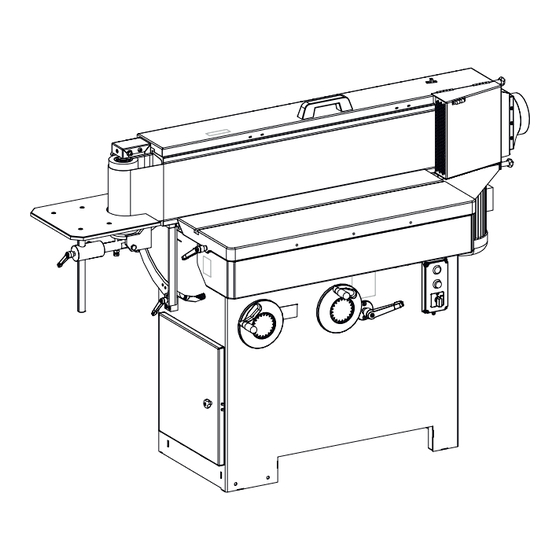
FS 700 K Machine overview Machine overview Overview Fig. 3: Machine overview Machine frame Adjust machine table height Adjust sanding unit inclination angle Machine table Support table - sanding curves Sanding unit (tiltable) Sanding belt cover Extraction flap (tiltable) Extraction connection... -
Page 26: Pictograms, Signs And Labels
Machine overview Pictograms, signs and labels Fig. 4: Location of the machine sticker Fig. 5: Machine sticker overview Sanding belt rotation direction Sanding belt tensioning Adjust the machine table horizontally / clamping lever Adjust sanding unit inclination angle Adjust machine table height / clamping lever Machine data plate Motor power information... -
Page 27: Information On The Machine Data Plate
FS 700 K Machine overview Information on the machine data plate Fig. 6: Machine data plate Manufacturer information Model type Machine number Electrical connection Year of construction Additional information (optional) Operation and display elements Fig. 7: Operation and display elements... -
Page 28: Sanding Belt Cover
Machine overview Clamping screws - extraction flap (extend the processing surface for longer workpieces) Adjust the machine table horizontally / clamping lever Sanding unit inclination angle - clamping lever 10 Sanding unit inclination angle scale 11 Adjust support table height - clamping lever Sanding belt cover Fig. -
Page 29: Transporting, Packing, Storing
FS 700 K Transporting, packing, storing Transporting, packing, storing Transport inspection Upon arrival, inspect the shipment to ensure that it is complete and has not suffered any damage. If any transport damage is visible from the outside, do not accept the delivery or only accept it with reservation. -
Page 30: Unloading / Transport
Transporting, packing, storing Unloading / transport The machine is delivered partly assembled and is attached to the pallet with several transport brackets. Remove the transport brackets before moving the machine to the installation loca- tion. The machine can be transported with a crane, forklift, pallet jack or rolling car- riage. -
Page 31: Transport With A Forklift Truck
FS 700 K Transporting, packing, storing Remove transport brackets. Fig. 10: Transport with a pallet truck Unloading ramp Transport bracket Push the forks under the recess in the machine frame. Unload the machine from the pallet with the pallet truck. -
Page 32: Transport With A Crane
Transporting, packing, storing 6.5.3 Transport with a crane WARNING Incorrect handling of the machine Severe injuries and material damage due to falling machine. − Do not lift the machine using the machine table, support table, extendable frame or by the hand grips. −... -
Page 33: Transport With A Rolling Carriage
FS 700 K Transporting, packing, storing Fig. 13: Lifting the machine incorrectly Lift machine. 6.5.4 Transport with a rolling carriage The rolling carriage and the lifting bar (option) facilitate the task of transporting the machine. Fig. 14: Transport with a rolling carriage... -
Page 34: Setup And Installation
Setup and installation Setup and installation Space requirement min. 2000 mm Fig. 15: Space requirement Installation location requirements: ● Sufficiently stable and proper load-bearing capacity of the work surface. ● Sufficient lighting of the working area. ● Sufficient clearance or screening from neighbouring workstations. ●... - Page 35 FS 700 K Setup and installation Fig. 16: Levelling the machine Spirit level Adjustable foot Tool: ● Spirit level Align the adjustable feet, until the machine stands firmly on the floor. Align and level the machine. Check the alignment of the machine using a spirit level both lengthways and crossways on all machine sides.
-
Page 36: Install
Setup and installation Install 7.3.1 Mount the extraction connection Fig. 17: Mount the extraction connection Extraction connection Extraction flap Tool: ● Allen key Tilt the extraction flap upwards and mount. Attach the extraction connection using nuts and screws to the machine stand. -
Page 37: Mount And Set The Support Table
FS 700 K Setup and installation Fig. 18: Remove the plastic connector Plastic connector Internal screws Mount the clamping screws with nuts. Fig. 19: Mount the clamping screws with nuts Close the extraction flap. Tighten the clamping screws. 7.3.2 Mount and set the support table... - Page 38 Setup and installation Fig. 20: Mount the support table brackets Hexagon screw Adjusting nuts 1 Holder bar Adjusting nuts 2 Locking nut Tool: ● Combination spanner Push the hexagon screw through the holder. Turn the adjusting nut (1) on the screw. Place the holding bar on the screw.
-
Page 39: Attach The Dust Extraction Hose
FS 700 K Setup and installation Fig. 21: Position support table Adjusting nuts 1 Adjusting nuts 2 Idle roller Locking nut The idle roller rotates in the centre of the table recess. Table rubs against the idle roller. Position the support table in such a way that the idle roller rotates in the centre of the table recess. -
Page 40: Connect Electrics
Setup and installation ● The dust extraction hose must be electroconductive and grounded to prevent electrostatic build up. ● Only use flame-retardant extraction hoses. ● Use extraction with reduced dust emission to clean dust from the machine. Ø 140 mm Fig. - Page 41 − It is prohibited to open the electrical box on the machine without the express authorisation from the Felder Group Service Department. Violating this stipulation will invalidate any guarantee claims. NOTICE...
- Page 42 Setup and installation WARNING Oversized preliminary fuse of the electrical connection Serious physical injury or material damage due to fire − Make preliminary fuse under consideration of the specification in the circuit diagram. Personnel: ● Qualified electrician Protective equipment: ● Protective clothing ●...
-
Page 43: Adjustments And Tool Changes
FS 700 K Adjustments and tool changes Adjustments and tool changes Sanding belts ● Only use appropriate sanding belts. ● Never use a torn sanding belt. ● Ensure that the surfaces of the rollers are clean and free of dust before attaching a sanding belt. - Page 44 Adjustments and tool changes Loosen the clamping screws. Swing the extraction flap upwards. Open protective cover. Move the lever until the sanding belt tension locks into place. Pull the belt out of the machine in a twisting motion. Place in a new sanding belt in the correct rotational direction. ●...
-
Page 45: Height Adjustment - Machine Table / Support Table
FS 700 K Adjustments and tool changes Tighten the clamping screws. Height adjustment - machine table / support table NOTICE Moving machine components Material damage − The machine and the support table must not touch the sanding belt. − Adjust so that there is sufficient distance between the sanding belt and the machine and support table. -
Page 46: Adjusting The Angle - Support Table
Adjustments and tool changes To move the support table to the desired height position. Clamp the clamping lever. Horizontally adjust machine / support table Loosen side adjustment clamping lever. Push or pull working table into position. Tighten the clamp lever for the side adjustment. Adjusting the angle - support table Setting: 90°... - Page 47 FS 700 K Adjustments and tool changes Fig. 29: Measure distance Angle position A: Value of X and Y is equal. Value of X and Y is not equal. Fig. 30: Adjusting angle A Loosen locking nuts. Set the position of the table extension with the adjusting screws.
- Page 48 Adjustments and tool changes Angle position B: Value of X and Y is equal. Value of X and Y is not equal. Fig. 31: Adjust angle B Release clamping screw (countersunk-head screws). Set the position of the table extension with the adjusting screws.
-
Page 49: Adjust Sanding Unit Inclination Angle
FS 700 K Adjustments and tool changes Adjust sanding unit inclination angle Fig. 32: Sanding unit inclination angle Inclination angle scale Clamping lever Adjust sanding unit inclination angle Loosen the clamping lever. Rotate the handwheel, in order to tilt the aggregate: ●... -
Page 50: Extending The Machining Area (Long Workpieces)
Adjustments and tool changes Extending the machining area (long workpieces) Fig. 33: Extend the processing surface Extraction flap Clamping screw or remove the workpiece stop. Loosen the clamping screw. Tilt the extraction flap upwards and lock into place. Sanding belt oscillation on / off The oscillation stroke can be switched on or off to change the sanding pattern. - Page 51 FS 700 K Adjustments and tool changes Fig. 34: Sanding belt oscillation on / off Green start button - switch the machine on Mode switch - Sanding belt oscillation Switch on the machine with the green [start] button. Turn the oscillation switch to position ON or OFF.
-
Page 52: Use
Switch on the machine Fig. 35: Switching the machine on / off Green start button - switch the machine on Connect the machine to the main power supply. Press the green [start] button. or switch the sanding belt oscillation on / off. -
Page 53: Switch Off / Emergency Stop
FS 700 K Switch off / Emergency stop Fig. 36: Switch off / Emergency stop Red stop button Press the red [Stop] button. �� Machine will stop immediately. Wait until the sanding belt has come to a complete stop. Disconnect the machine from the main power supply. -
Page 54: Authorised Working Methods
Fig. 37: Working positions Working area for flat surfaces Working area for curves 9.3.2 Authorised working methods All other working techniques that deviate from the following uses are improper on this machine and therefore not permitted: ● Sanding of longitudinal sides on the longitudinal sanding side of the machine. -
Page 55: Sanding On The Longitudinal Side Of The Machine
FS 700 K 9.3.4 Sanding on the longitudinal side of the machine The following operations can be carried out: ● Sanding joist sides. ● Sanding of radius. ● Correcting uneven areas (Window angle). ● Head sanding. Fig. 38: Sanding at the front of the machine... -
Page 56: Sanding With Tilted Unit
9.3.5 Sanding with tilted unit The tilting sanding unit that can be swivelled from 90° - 45° makes it possible to sand: ● Mitred edges ● sharp edges ● chamfered edges Fig. 39: Sanding with tilted unit Workpiece fence (accessory) NOTICE Moving machine components Material damage... -
Page 57: Sanding Of Long Workpieces
FS 700 K Switch machine on. First place the workpiece against the fence and then guide it to the sanding belt. 9.3.6 Sanding of long workpieces Fig. 40: Sanding of long workpieces WARNING Running sanding belt Through contact with the running sanding belt it could cause serious cut or abrasion injuries. -
Page 58: Sanding Curves
9.3.7 Sanding curves Using this working technique sand curved workpieces with large radius. Fig. 41: Sanding curves Sanding curves on the support table NOTICE Moving machine components Material damage − Remove workpieces and fences from the support table before tilting. WARNING Running sanding belt Through contact with the running sanding belt it could cause... - Page 59 FS 700 K Switch machine on.
-
Page 60: Maintenance
Maintenance 10 Maintenance 10.1 Maintenance schedule Chap. Task to execute 10.2 Clean the machine 10.3 Clean the sanding belt 10.4 Lubricating the height adjustment spindles 10.4 Lubricating the tilting spindle 10.5 Change the graphite sliding mesh ... -
Page 61: Clean The Sanding Belt
Maintenance Perform a visual inspection of all machine parts. No damage Damage identified. Repair damage immediately. �� If it is not possible, contact the Felder Group service centre. 10.3 Clean the sanding belt CAUTION Running sanding belt Cut and abrasion injuries from the sanding belt −... -
Page 62: Lubricate The Height And Tilt Spindle
Maintenance 10.4 Lubricate the height and tilt spindle Fig. 42: Preparation for maintenance work Adjust sanding unit inclination angle Adjust machine table height Machine table height - clamping lever Sanding unit inclination angle - clamping lever Switch off the machine and secure it against being switched on again. Loosen the clamping lever. - Page 63 FS 700 K Maintenance Lubricating the height adjustment spindles Fig. 43: Lubricating the height adjustment spindles Height guide Height spindle Cover plate Protective equipment: ● Protective clothing ● Protective gloves ● Safety goggles Tool: ● Cleaning cloths ● Vacuum cleaner ●...
-
Page 64: Sanding Belt Support - Change The Graphite Sliding Mesh
Maintenance Lubricating the tilting spindle Fig. 44: Lubricating the tilting spindle Tilting spindle Cover plate Protective equipment: ● Protective clothing ● Safety goggles Tool: ● Cleaning cloths ● Vacuum cleaner ● Allen key Material: ● Machine grease Remove the cover plate. Through the frame opening, lubricate the tilting spindle with machine grease. - Page 65 FS 700 K Maintenance Fig. 45: Change the graphite sliding mesh Sanding belt support Glue a new graphite sliding mesh on. Fit the sanding belt. Check the run of the sanding belt. The sanding belt runs smoothly. The sanding belt rubs on the sanding belt support.
-
Page 66: Troubleshooting
Troubleshooting 11 Troubleshooting 11.1 What to do in the event of malfunctions WARNING Improper troubleshooting Severe injuries and damage to property − Troubleshooting may only be carried out by authorised, trained personnel who are familiar with how to operate the machine and are in strict observance of all safety instructions. - Page 67 FS 700 K Troubleshooting Fig. 46: Dismount cover Start machine. Adjust adjusting nut 1. Fig. 47: Set the run of the sanding belt higher Adjusting nut 1 Adjusting nut 2...
- Page 68 Troubleshooting As soon as the sanding belt runs in the centre of the idle and drive roller tighten adjusting nut 2. Sanding belt runs in the centre. Fig. 48: Sanding belt run central Sanding belt is not central. Fig. 49: Sanding belt is too low Adjust adjusting nut 1.
- Page 69 FS 700 K Troubleshooting Dismount cover. Fig. 50: Dismount cover Start machine. Loosen adjusting nut 2 and tighten adjusting nut 1. Fig. 51: Set the run of the sanding belt lower Adjusting nut 1 Adjusting nut 2...
- Page 70 Troubleshooting Check, whether the sanding belt runs in the centre of the idle and drive roller. Sanding belt runs in the centre. Fig. 52: Sanding belt run central Sanding belt is not central. Fig. 53: Sanding belt is too high Adjust adjusting nut 2.
-
Page 71: Faults, Causes And Repairs
FS 700 K Troubleshooting 11.4 Faults, causes and repairs 11.4.1 Fault with the sanding belt controls Fault description Cause Remedy The sanding belt is slipping off The sanding belt is not running in the Set the height of the sanding the sanding unit. - Page 72 Troubleshooting Fault description Cause Remedy The workpieces are being Sanding belt support is not parallel. Contact Felder Group service sanded unevenly. centre. Lines appear along the work- The sanding belt grains are crushed Fit a new sanding belt. piece length during the or the sanding belt is damaged as ⮫ Chapter 8.2 ‘Change /...
-
Page 73: Attachment
FS 700 K Attachment 12 Attachment 12.1 About spare parts NOTICE Wrong or faulty spare parts Material damage, malfunction, machine failure − Only use spare parts approved by the manufacturer (see spare parts list). If unauthorised spare parts are fitted into the machine, all warranty, service, compensation and liability claims against the manufacturer and their contractors, dealers and representatives will be rejected. -
Page 74: Disposal
Attachment 12.2 Disposal ENVIRONMENT Disposal of machine components Used electrical materials, electronic components, lubricants and other auxiliary substances must be treated as special waste and may only be disposed of by specialised, licensed firms. The machine consists of many different materials for which different disposal conditions may apply depending on national legislation. - Page 76 FELDER KG KR-Felder-Straße 1,A-6060 HALL in Tirol, AUSTRIA Telephone: +43 5223 5850 0 Email: info@felder-group.com Internet: www.felder-group.com...
Need help?
Do you have a question about the FS 700 K and is the answer not in the manual?
Questions and answers
Регулировка полезной пилы