
Related Manuals for MultiDyne HoneyBadger

Summary of Contents for MultiDyne HoneyBadger
- Page 1 HoneyBadger Video/Audio/Intercom/Data Extension Platform USER MANUAL 252 INDIAN HEAD RD, KINGS PARK, NY 11754 USA (877) 685-8439 / (516) 671-7278 / FAX (516) 671-3362 sales@multidyne.com www.multidyne.com...
-
Page 2: Table Of Contents
DOCUMENT REVISIONS Table of Contents Document Revisions ..........................2 Safety Info ............................. 3 Overview ............................5 Feature Descriptions ........................6 Operation ............................13 Accessories / Field-Replaceable Units ..................18 Specifications ..........................20 Contact Info ..........................23 Copyrights ............................ 24 Document Revisions Revision Description Date Author... -
Page 3: Safety Info
All Electrical Work to the facility must be performed by a qualified Licensed Electrician. All local Electrical Codes must be followed and, if necessary, must be inspected by a Local or State Inspector. All servicing of MultiDyne equipment must be performed at the factory by a MultiDyne trained service technician or engineer. - Page 4 Laser Safety Information This unit is classified as a CLASS 1 LASER PRODUCT according to EN60825-1 (EU) and FDA 21CFR 1040.10 (USA). Class 1 laser products are considered safe and do not result in biological hazard if used according to these instructions. Warning –...
-
Page 5: Overview
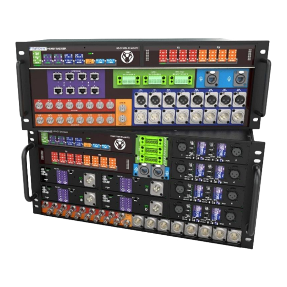
OVERVIEW 1. Overview The HoneyBadger (HB) is a multi-format transceiver that multiplexes a wide collection of broadcast signal types onto 2 fibers. This includes SDI, analog and intercom audio, Gigabit Ethernet, Genlock (sync), serial data (RS-232/422/485) and GPIO. This is all accomplished with a 4RU local box and a 5RU remote unit. -
Page 6: Feature Descriptions
FEATURE DESCRIPTIONS 2. Feature Descriptions 2.1. Front Panel HB-DC-DBR (5RU) A. Status Indicators – Intercom, Ethernet, Sync, Data/Tally, Audio a. Intercom & Audio Each LED is shared between 2 audio channels. For example, for Intercom (I-COM) IN “A”, the LED will light when audio is detected on either channel 1 [CH1] or channel 2 [CH2]. b. - Page 7 Channels transport up to 3Mbps. The LEDs in the front will turn on showing the data paths are active. The HoneyBadger is built with 422 selected as the default mode. RS-232 and RS-422 operate in full-duplex mode. RS-485 operates in half duplex and is available by contacting MultiDyne.
- Page 8 FEATURE DESCRIPTIONS 2.2. Front Panel HB-DC-DBL (4RU) Since both boxes are mirror images of each other, only the differences from 5RU are shown here. See Section 2.1 for full panel descriptions. A. Intercom Matrix Patch balanced audio to interface with Matrix frames. Section 2.4.1 has detailed pinouts.
- Page 9 FEATURE DESCRIPTIONS 2.3. Rear Panel (Both Models) A. UFP Universal Fiber Plate for fiber I/O interface. Fiber options are chosen at time of order. See Section 6 for all available fiber types. B. AC Power supplies + cover One power supply is installed by default. For redundnacy in case of supply failure, a 2 unit can be installed.
- Page 10 FEATURE DESCRIPTIONS 2.4. Pinouts 2.4.1. Intercom Matrix Pin Function OUT+ OUT- Diagram 10 | P a g e...
- Page 11 FEATURE DESCRIPTIONS 2.4.2. Intercom Pin Function Ground Channel 1 Channel 2 2.4.3. Data Contact MultiDyne for running RS-232 or 485 Pin Function TX+ 422 Out TX- 422 Out RX+ 422 In RX- 422 In Ground Diagram 11 | P a g e...
- Page 12 FEATURE DESCRIPTIONS 2.4.4. GPIO & Tally Pin Function GP Input GP Output Tally In Tally Out Ground Diagram 2.4.5. Audio Industry standard for XLR balanced audio Function Ground Balanced Audio + Balanced Audio - 12 | P a g e...
-
Page 13: Operation
OPERATION 3. Operation 3.1. Intercom (4x) [HB-DC-DBR Only] The Intercom units provide a means to interface between two channels of 2-wire party-line intercom audio and two channels of 4-Wire analog line-level signals. The unit can perform auto-nulling for each channel with the push of a button. In addition, each of the 4-Wire input and output channel levels are monitored and displayed on front panel VU meters. - Page 14 OPERATION Switch 2 Set to RTS or Clear-Com mode. To be compatible with RTS units, push the GAIN L/GAIN H switch UP; to be compatible with Clear Com units push switch DOWN. This switch adjusts the gain needed to interface between the 4-wire to 2-wire signals and it also adjusts the gain from the 2-wire to 4-wire signals.
- Page 15 OPERATION and the resulting lack audio return loss will result in feedback. Note that if the party line has been altered after a null has been done, the status LEDs will not update on their own. They do not monitor status on a continuous basis.
- Page 16 OPERATION 3.2. MIC/Line Inputs (8x) [HB-DC-DBR Only] The MIC level inputs contain microphone preamplifiers intended for use with low-level microphones or line-level audio sources. It features adjustable input gain and impedance settings, LED metering, and individual 48V/12V phantom power (or A-B powered) for each input. The display area has 2 parts: the VU meter itself, and the two blocks for gain control next to it.
- Page 17 LED -2dB position will light up alone. The LEDs for the gain on mic mode work similarly. • Default max audio levels are +24dBu. Contact MultiDyne for other custom levels, e.g., +18. • Input impedance can also be selected if needed (2.4k, 660 ohm). Contact MultiDyne.
-
Page 18: Accessories / Field-Replaceable Units
ACCESSORIES / FIELD-REPLACEABLE UNITS 4. Accessories / Field-Replaceable Units Description Part Number Redundant/Replacement External Power Supply OEM-00010 Pull Handle 4RU HWR-00087 Pull Handle 5RU HWR-00093 Fan Assembly (Single) 80-0123-004 18 | P a g e... - Page 19 ACCESSORIES / FIELD-REPLACEABLE UNITS 4.1 Fiber Plate Options The 3-digit suffix of the top-level part number indicates the fiber connector type. -LC2 LC/UPC -SC2 SC/UPC -ST2 ST/UPC -OC2 ® ® Neutrik opticalCON 19 | P a g e...
-
Page 20: Specifications
SPECIFICATIONS 5. Specifications 5.1 HB-DBL 4RU Unit Dimensions & Weight WEIGHT: ~38 lbs. [17kg] 20 | P a g e... - Page 21 SPECIFICATIONS 5.2 HB-DBL 5RU Unit Dimensions & Weight WEIGHT: ~ 42lbs. [19kg] 21 | P a g e...
- Page 22 SPECIFICATIONS 5.3 Electro-Optical Fiber Type Singlemode Fiber Polish Ultra-physical contact [UPC] Fiber Connectors LC, ST, SC, or Neutrik® opticalCon® DUO 5.4 Power HB-DC-DBL ~70W HB-DC-DBR ~70W Input: 90–264Vac, 47/63Hz OEM-00010 Supplied AC-DC Power Supply Output: 48Vdc 4.17A (200W) 22 | P a g e...
-
Page 23: Contact Info
CONTACT INFO 6. Contact Info Contact support@multidyne.com 23 | P a g e... -
Page 24: Copyrights
COPYRIGHTS 7. Copyrights “opticalCON” is registered trademarks of NEUTRIK AKTIENGESELLSCHAFT 24 | P a g e...
Need help?
Do you have a question about the HoneyBadger and is the answer not in the manual?
Questions and answers