Advertisement
Available languages
Available languages
Quick Links
WARNING! Read Instructions before using the machine
Introduction
Premiere launched the first of its extensive range of floorcare products over 85 years
ago. Its first range of cleaning and maintenance machines came onto the market in
1966 and are now second to none for efficiency and design. For literature covering
the complete range of both wet and dry vacuums and rotary polishers please ring
our head office in Cheltenham.
Quality Control Procedures
The inspection of component parts and finished machines is governed by detailed
performance, quality and electrical safety specifications. Test results are recorded and all
quality assurance systems and records are approved and inspected by The British
Standard Institution in accordance with:-
BS EN ISO 9001
Certificate No. FM 01933
Approvals
Details of certifications applicable to individual models are given in the Sales Brochure
which is available upon request.
tested to:
DIN EN 60335-1 / DIN EN 60335-2-69
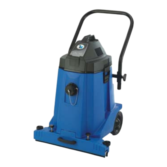
Technical Information WPU 140
WPU 140PP
Acoustic Noise Level:
67 dB
69 dB
Caution
This appliance is not intended for use by persons (including children) with reduced
physical, sensory or mental capabilities, or lack of experience & knowledge, unless they
have been given supervision or instruction concerning use of the appliance by a person
responsible for their safety.
Children should be supervised to ensure that they do not play with the appliance
Machine Care
Operating Instructions
The manufacture of safe and dependable machinery is not simply a question of checking
procedures at the end of the production line. It is reliant upon in-built quality at design
WPU 140
stage and rigid control on the specification of every component part.
As owner/operator of a Premiere machine, continued reliability and performance now
depends upon the care taken in keeping your machine well maintained.
The plug of the supply cord shall be removed from the socket-outlet before cleaning
the appliance or undertaking maintenance operations.
• The power cord has to be regularly inspected for signs of damage. If the power supply
cord is damaged, it has to be replaced.
• After use, the whole machine, including the cable, should be cleaned with a DAMP
cloth using a dilute solution of Premiere M.P.9. Multi-purpose cleaner. All surfaces
should then be polished with a clean duster untiI dry.
• DO NOT use acid descalers, abrasives or powerful solvents such as paint strippers,
which may scratch, etch or dull surfaces.
• Accessories should be cleaned with a DAMP cloth using a dilute solution of Premiere
M.P.9. Multi-purpose cleaner.
• Store in a dry place.
• To ensure efficient motor cooling and maximum suction , disposable paper bags or re-
useable cloth zip bags should be changed or emptied frequently. Both grill filters (if
used) and cloth filter should be regularly shaken, vacuumed or hand washed. If
washed do not attempt to refit until completely dry. The wet filter should be regularly
cleaned by rinsing under a tap.
• Continued use during a voltage increase will cause overheating and may result in the
motor burning out. If a noticeable increase in voltage supply occurs, it is advisable to
switch off and investigate.
GB
• Mini vacuum units are designed for dry use only. Any attempt to pick up liquids such
as Coffee spillages may irrepairably damage the motor and create an electrical hazard.
• Attempting to operate your machine without both the cloth filter, paper dust bag or
re-usable cloth zip bag is ill advised and may result in poor suction performance and
possibly premature motor failure.
• The socket-outlet is only for use with approved accessories supplied from Premiere
Products. Use of the socket for other purposes may result in electric shock.
• The Mini vacuum units are also suitable for commercial use, for example in hotels,
schools, hospitals, factories, shops and offices for other than normal housekeeping
purposes.
Warning
• The plug should not be subjected to undue stress by pulling on the supply cord.
• The following appliances are double insulated and should not be earthed: WPU 140.
• A 230V power supply is required for the use of a 3 pin fused plug.
• Fuse rating 13 amp.
• If the plug fitted to the appliance is not correct for your socket outlets it should be cut
off and the correct plug fitted. DESTROY the removed plug which will be dangerous if
plugged into a live socket.
• For moulded plugs, replacement fuse covers must be the same colour as the one
originally supplied. NEVER use with fuse cover omitted.
Cables and Extension leads
Each machine is designed for use with a specified cable. Similarly the specification and
length of any extension lead is critical to the safe and efficient operation of all Premiere
machines. We strongly advise that only cables and extension leads supplied by Premiere
are used. See Guarantee section.
Fitting/Adjusting Chassis Handle - DIAGRAM 1
•
Remove two handwheels (A) from chassis (B) by rotating anti- clockwise.
• Locate handle (C) over chassis (B) and align fixing holes.
• Place handwheels (A) in fixing holes of handle (C) and rotate clockwise to secure.
Note: The chassis handle is adjustable for two height positions.
Fitting/Removing Accessories
Floating Head
• Remove two handwheels (A) from location shafts (B) on floating head by rotating anti-
clockwise - DIAGRAM 2.
• Tilt machine backwards until handle of chassis rests on floor and base of machine is
exposed.
• Offer up floating head and locate bellows (A) over inlet spigot (B) - DIAGRAM 3.
• Align location shafts (C) with guides (D) in floating head cover and gently push floating
head into position - DIAGRAM 3.
• Place machine in upright position.
• Holding floating head in position locate handwheels (A) on location shafts (B) and rotate
clockwise to secure - DIAGRAM 4.
• Place blanking connector (A) onto inlet socket (B) on vacuum container - DIAGRAM 5.
• Apply pressure gently inwards and at the same time rotate connector clockwise to
ensure a positive seal.
Wander Hose and Accessory
• If floating head is attached to machine base raise it clear of floor by lifting two
handwheels (A) simultaneously until location shafts lock - DIAGRAM 6.
• Remove blanking connector (A) from inlet socket (B) by rotating anti-clockwise -
DIAGRAM 5.
• Place black connector (A) at end of hose into inlet socket (B) on vacuum container -
DIAGRAM 7.
• Apply pressure gently inwards and at the same time rotate connector clockwise to
ensure a positive lock.
• Slot two extension tubes firmly together.
• Press upper tube onto neck of pistol grip and lower tube into neck of suction floor tool
or chosen accessory.
Note: To revert to Floating Head option reverse procedures 1 to 6 above.
Operation of WPU 140
• Ensure that power supply is same as that stamped on serial plate on the machine.
• Plug machine into power socket and switch on.
• lf floating head is used methodically wheel machine backwards and forwards over area
to be cleaned.
• lf wander hose is used pull machine behind you holding the hose with your free hand,
vacuum the area to be cleaned methodically.
Warning:
• When the container is full, the cut-off float valve operates (denoted by change in note
of motor, and loss of suction).
• Switch off immediately, remove motor head and wet filter, disconnect hose and empty
container drum.
• If the machine does not start, or the machines performance becomes impaired, switch
off immediately and refer to the servicing section of this manual.
• Should foam be seen to be issuing from the machine, the operator should switch off
immediately.
• The cut-off float valve assembly should be regularly cleaned and examined for signs of
damage.
Emptying of Machine Container
• Release two retaining fasteners and remove motor head of vacuum unit - DIAGRAM 8.
• Loosen rubber moulding (A) which fits over top rim of vacuum unit container and
remove wet filter - DIAGRAM 9.
• Disconnect wander hose if fitted.
• Wheel machine to suitable emptying location.
• Detach drain hose from chassis.
• Place hose outlet over emptying location and remove blanking valve.
• Before re-commencement of use clean wet filter by rinsing under a tap and check float
valve assembly to ensure correct operation - DIAGRAMS 10 & 11.
To Operate WPU 140 as a Dry Vacuum
To fit Cloth Dry Filter
• Release two retaining fasteners and remove motor head of vacuum unit - DIAGRAM 8.
• Loosen rubber moulding (A) which fits over top rim of vacuum unit container and
remove wet filter - DIAGRAM 9.
• Ensure that both float valve assembly and inside of container are dry.
• Fit cloth dry filter by firmly positioning rubber moulding (A) over rim of vacuum
container - DIAGRAM 9.
• Replace and secure motor head with two retaining fasteners.
Advertisement

Summary of Contents for Tuv nord Premiere WPU 140
- Page 1 • Place machine in upright position. Machine Care Operating Instructions • Holding floating head in position locate handwheels (A) on location shafts (B) and rotate The manufacture of safe and dependable machinery is not simply a question of checking procedures at the end of the production line. It is reliant upon in-built quality at design clockwise to secure - DIAGRAM 4.
- Page 2 Servicing We continue to reserve the right to alter the designs of any products as part of a further Although your new vacuum should give many years of trouble free operation, an process of improvement, and items supplied may therefore vary from those illustrated in annual service by our engineer is recommended to minimise the risk of an this publication.
- Page 3 Entretien des machines Mise en place et dépose des accessoires Mode d’emploi La fabrication de machines fiables et sans danger ne repose pas simplement sur des La tête flottante • Détacher deux roues à main (A) des guides d'emplacement (B) sur la tuyère pour les contrôles effectués à...
- Page 4 Mode d'emploi du WPU 140 comme aspirateur à sec satisfont aux normes de qualité et de sécurité les plus strictes. Montage du filtre en tissu sec La décision de réparer ou de remplacer un élément donné ou la machine revient •...
- Page 5 Maschinenpflege Einbau/Ausbau der Zubehörteile Bedienungsanleitung Die Qualitätssicherung bei der Herstellung von betriebssicheren und zuverlässigen Flexibler Saugkopf Maschinen umfaßt weit mehr als die Endkontrolle am Ende des Fertigungsverfahrens; sie • Schrauben (A) entgegen dem Uhrzeigersinn aus den Positionierstiften (B) am flexiblen WPU 140 erfordert eine hochqualitätige Konstruktion, die strengsten Auflagen und Saugkopf herausdrehen (BILD 2).
- Page 6 Wartung Gesundheit und Sicherheit am Arbeitsplatz Premiere Products hat alle erdenklichen Anstrengen unternommen, die Unsere Sauger versprechen eine mehrjährige, störungsfreie Funktionsweise. Betriebssicherheit ihrer Maschinen zu gewährleisten, sofern diese sachgemäß Wir empfehlen dennoch eine jährliche Wartung durch unsere Händlervertretung angewendet werden. vornehmen zu lassen, um die Gefahr einer Panne völlig auszuschließen.
- Page 7 • Handräder (A) in den Aufnahmelöcher am Griff (C) positionieren und im Uhrzeigersinn Gebruiksaanwijzing Machine-onderhoud De produktie van veilige en betrouwbare machines is niet uitsluitend een kwestie van bis zum Einrasten drehen. controleprocedures aan het eind van de produktielijn. In veel grotere mate is het een Bitte beachten: Der Rahmengriff läßt sich auf zwei verschiedene Höhen einstellen.
- Page 8 • Stoffilter einsetzen. Dabei Gummidichtung (A) wieder fest am Behälterrand Wir behalten uns weiterhin das Recht vor, das Design unserer Maschinen im Sinne einer Weiterentwicklung zu verändern. Produkt und Zubehör können daher von den hier andrücken (BILD 9). • Deckel auflegen und mit den beiden Schnappverschlüssen sichern. illustrierten abweichen.
-
Page 9: Instrucciones De Funcionamiento
Instrucciones de funcionamiento Cuidado del aparato Para colocar/retirar los accesorios La fabricación de maquinaria segura y fiable no es simplemente una cuestión de Boquilla fotante comprobar procedimientos al final de la línea de producción. Es necesario garantizar una • Sacar los dos pequelos volantes (A) de los ejes (B) dele boquilla flotante girando en WPU 140 calidad intrínseca a nivel de diseño y un control riguroso en la especificación de cada sentido contrario a reloj - DIAGRAMA 2. - Page 10 • Asegurar que tanto el conjunto de válvula de expansión como el interior del sustituidas bajo previo acuerdo y con autorización de Premiere Products en el caso de un recipiente están secos. fallo significante de fabricación, (habiendo sido suministrado directa o indirectamente) •...
- Page 11 Cuidados com os Aparelhos Montagem/remoção de acessórios Modo de usar Para fabricar aparelhos de segurança e confiança não basta apenas verificar os Cabeça flutuante resultados ao fim da linha de produção. É preciso garantir uma qualidade intrínsica no • Retirar os dois manípulos (A) dos veios de montagem (B) na cabeça flutuante girando WPU 140 estágio de concepção como também controle rigoroso na especificação de cada peça da direita para a esquerda - DIAGRAMA 2.
- Page 12 Operação dos aspiradores WPU 140 como aspiradores para trabalho a seco técnicos ou os agents de serviço por ele designados sejam competentes e que qualquer Montagem do filtro de pano para trabalho a seco trabalho executado seja da mais alta qualidade e de acordo com as normas de •...
-
Page 13: Istruzioni Per L'uso
• Inclinare all'indietro l'apparecchio fino a quando Io chassis si poggia al pavimento e la Manutenzione dell'apparecchio Istruzioni per l’uso La produzione di apparecchi sicuri ed affidabili non si avvale soltanto di procedure di base dell'apparecchio è visibile. • Posizionare la testata flottante e i soffietti (A) sull'attacco (B) - SCHEMA 3. controllo al termine della catena di montaggio, ma anche sulla qualità... - Page 14 • Rimontare la testata alloggiamotori e fissarla mediante i due fermagli. Qualunque reclamo inoltrato ai sensi della presente garanzia dovrà essere Assistenza tecnica accompagnato da un documento che provi l'acquisto. Anche se aspirapolvere appena acquistato dovrebbe funzionare per anni senza creare Si declina ogni responsabilità...
- Page 15 • Plasser maskinen i oppreist stilling. Maskinpleie Bruksanvisning • Med det flytende munnstykket i stilling skal du finne håndskruene (A) på styreakslene Produksjon av trygge og pålitelige maskiner er ikke bare et spørsmål om å kontrollere rutinene på tampen av samlebåndet. Den er avhengig av innebygget kvalitet på (B) og skru dem med klokken til de sitter godt –...
- Page 16 standardkravene. De medfølges av bruksanvisninger som bør leses nøye av personen Hvis service er nødvendig, må du ringe serviceagenten og angi modellnavnet som står som bruker maskinen og personen som har ansvaret for rengjøringsarbeidet. Ekstra på maskinbeholderen og serienummeret som står på serienummerskiltet på motorhuset. kopier kan fås på...
Need help?
Do you have a question about the Premiere WPU 140 and is the answer not in the manual?
Questions and answers