MTI Industries SAFE-T-ALERT SA-10XL - Marine Gasoline/Propane, Bilge Water And Fire Deterctor Manual
- User manual (2 pages)
Advertisement
Introduction

PLEASE READ CAREFULLY AND SAVE
 ATTENTION: This user's manual contains important detector installation, operation, trouble shooting and warranty information. Read, follow, and keep this manual for future reference.
NOTE: If you install or purchase this detector for another person, give this manual to that person.

WHY EVERY BOAT NEEDS A COMBINATION DETECTOR
Every year, boating injuries and deaths can be attributed to explosions that could have been avoided. Fumes from even a half cup of gasoline have the explosive force of six sticks of dynamite. With a boat's gas-powered or propane-powered engines, vapors can easily develop in pumps, tanks, lines, or carburetors and cause explosions or fires.
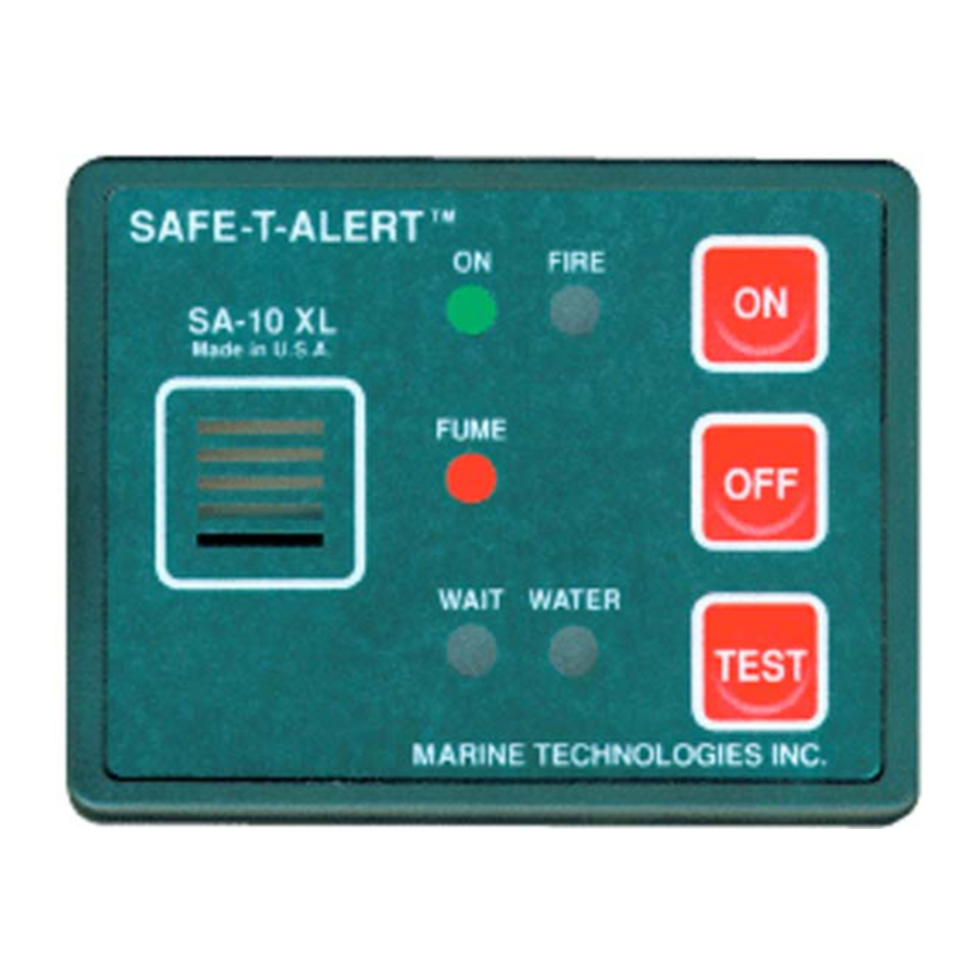
The SAFE-T-ALERT™ SA-10XL combination detector system is exclusively designed, tested for use in the harsh marine environment. The unit is an early warning detector that monitors for the buildup of explosive gases, high heat and heat from fire, and bilge for high water.
LIMITATIONS OF COMBINATION DETECTORS
Detectors will not work without power. Some reasons your detector may not have power include an open circuit breaker, a blown or missing fuse, a broken wire or improper wire crimp connection.
This detector may not be heard. The detector's loudness is designed to meet or exceed regulatory standards; however, the alarm may not be heard if units are remotely located. Individuals who are hard-of-hearing, have consumed alcoholic beverages, have taken prescription, non-prescription or illegal drugs may not hear the alarm. If your boat has any sleeping areas, consider installing additional detectors in that area.
This detector will only indicate the presence of gasoline fumes or heat at the sensor. The sensor cannot monitor a compartment that is separated by a bulkhead. Gasoline fumes and heat may be present in other areas. MTI recommends that sensors be installed in ALL compartments containing fuel tanks and/or engine(s) and compartments where gasoline or propane fumes or heat may accumulate.
INSTALLATION INSTRUCTIONS
Assemble the following supplies: An 3/8" (9.525 mm) electric drill, ¼" (6.35 mm) and 7/64" (2.77812 mm) drill bits, 2-1/8" (53.975mm) hole saw, electric jigsaw, screwdrivers (Phillips and slotted), stainless-steel pan head screws, washers bolts, nuts, locking nuts, silicone sealant, 18-gauge wire, 14-gauge wire, inline fuse holder, 1A fuse, wire stripper, crimping tool, crimp connectors, adhesive-lined heat shrink tubing, split loom wire wrap, heat gun, wire supports, and cable ties.
When you have the supplies on hand, take the following steps:
Installing the Control Panel
- Locate the control panel at the helm where it can be easily seen and heard. Check first to be sure that there is at least 3 inches (76.2 mm) of clearance behind the location to allow for mounting and wiring. Drill a 2 1/8 inch (53.975 mm) hole and mount the control panel. Use a marine-grade silicone sealer if the unit is exposed to the weather. DO NOT CONNECT POWER UNTIL THE INSTALLATION IS COMPLETE.
- Connect the cable assembly to the control panel and run it to the engine compartment. Secure the run every 18 inches (457.2 mm) with plastic wire supports.
Installing the Fume Sensor
- Locate the fume sensor in a dry area on a forward bulkhead in the engine compartment. The sensor should be at the same height as the starter motor. Orient the sensor so that the 4-wire cable is facing down. This will prevent any water or condensed water vapor from entering the unit. Connect the cable assembly from the control panel to the sensor.
![]()
Gasoline and Propane are heavier than air. Mount the sensor at the engine starter height. Starter height is dependent on the engine installation - Connect a 1A inline fuse holder to the red (+) lead of the control panel. Run a length of red (+) 18-gauge wire to the positive terminal on the 12V main battery. Run a length of 18-gauge yellow or black (-) wire to the negative terminal on the 12V battery. Use ring-type insulated crimped connectors at the battery end of the run. Secure the run every 18 inches (457.2 mm) with plastic wire supports. As added protection, use adhesive-lined shrink tubing on all crimped connections.

Installing the Water Sensor
- Mount the water sensor about 4" (101.6 mm) above the automatic bilge pump switch. Connect one blue lead to a water sensor wire and the yellow lead to the other water sensor wire. Do not mount the sensor where it will get wet or submerged in water during normal operation. Do not mount with the cable up as water can run into the sensor assembly and damage the sensor assembly. Connect the 20 foot (6096 mm) cable.
Installing the Fire/Heat Sensor
- Connect the white lead to one of the white heat sensor wires. Connect the Blue lead to one of the Heat Sensor Black wires. Install the sensor above the engine(s) and as high as possible in the compartment
- When installation is complete, run a system check of all sensors and the control panel. Be sure to turn the unit off when leaving the boat, as constant monitoring will run down the 12V battery.
The assembled system should look similar to the following:

ADDITIONAL INSTALLATION TIPS
- DO NOT mount the control panel under a cowling, or glass or plastic panel where it may not be seen or heard.
- DO NOT locate the fume sensor above batteries. Hydrogen from the batteries may cause false alarms.
- DO NOT locate the fume sensor behind any obstruction that will prevent air flow to the sensor.
- DO NOT locate the fume sensor on the aft bulkhead. Water on the sensor will cause permanent damage to the sensor and sensor assembly.
- DO NOT locate the fume sensor within 12 inches (304.8 mm) of exhaust lines. High heat may cause false alarms.
OPERATION
The SA-10XL has supervisory circuits to warn of a missing sensor, sensor assembly malfunction, disconnected or a broken connector sensor cable.
- Press the control panel's ON pad. The WAIT (YELLOW) light should light. Press the TEST pad to check the operation of the alarm sounder and alarm light. In about two minutes the WAIT (YELLOW) light will turn off and the ON (GREEN) light will light. The unit is now operational and is monitoring for all conditions.
- When the sensor detects fumes, heat, or bilge water above the alarm threshold levels, the alarm will sound and the RED alarm light will activate. The alarm will continue until the air in the monitored area returns to safe levels. See
PROCEDURES TO TAKE DURING AN ALARM.
TESTING
TEST THIS DETECTOR'S OPERATION AFTER THE BOAT HAS BEEN IN STORAGE, BEFORE EACH TRIP AND AT LEAST ONCE PER WEEK DURING USE.
NEVER ENTER THE ENGINE COMPARTMENT WITH AN OPEN FLAME OR LIT SMOKING MATERIALS. OPEN FLAMES AND SMOKING MATERIALS CAN CAUSE AN EXPLOSION AND OR FIRE. USE ONLY A BUTANE LIGHTER TO PERFORM THIS TEST, NEVER USE GAS SOAKED MATERIAL.
- With the unit on, check the sensor assembly light. The RED light should be lit.
- When the GREEN normal operation light is lit, the sensor assembly can be tested.
- SENSOR TEST: Direct the lighter towards the sensor and depress the lever to release gas into the sensor. The alarm should sound and the RED alarm light on the control panel should be lit.
- SUPERVISORY CIRCUIT TEST 1: Disconnect one end of the 20 foot (6096 mm) connector cable. The alarm should sound and the RED alarm light on the control panel should be lit.
- SUPERVISORY CIRCUIT TEST 2: Use a pull and rocking motion to remove the sensor (Figaro TGS 813) from the sensor assembly. The alarm should sound and the RED alarm light on the control panel should be lit.
- WATER SENSOR: Hold a wire with both ends stripped across both contacts on the sensor. The alarm should sound and the RED alarm light on the control panel should be lit.
- HEAT SENSOR: (Caution- Never use an open flame) Hold a lit 100 watt light bulb on the tip of the sensor. The alarm and light should activate in about 30 seconds.
IF THE UNIT DID NOT TEST PROPERLY, REFER TO THE TROUBLE SHOOTING GUIDE
MAINTENANCE
- Keep the fume sensor free of dust and debris. It is recommended that the fume sensor—Figaro TGS 813 (MTI Part No. SA-186-S) be replaced annually due to the contamination caused in the marine environment. To remove, pull straight out.
- Remove the fume sensor whenever the bilge compartment or engine compartment equipment is being cleaned, painted, power washed, etc. Direct contact with chemicals, WD-40, water, oil, etc. can cause permanent damage to the sensor.
TROUBLE SHOOTING GUIDE
| Problem | Cause |
No Power | Wire connections, missing or blown fuse, reversed wires, or defective unit. |
Locked In Wait | Replace the sensor assembly SA-186-SB. |
Immediate Alarm When Turned On | Cable disconnected or broken, Sensor assembly, check sensor assembly red light |
No Audible Alarm | Return unit for repair or replacement. |
No Alarm During Supervision Tests | Return unit for repair or replacement. |
Red LED On Sensor Assembly Is Off | Unit is off, Cable disconnected or broken, the SA-186-SB is defective. |
No Alarm When Sensor is removed | If panel tests OK; replace the sensor Figaro TGS 813. |
| No Alarm With Lighter Test | If the panel tests OK, replace sensor Figaro TGS 813. If that does not remedy condition, replace the sensor assembly SA-186-SB. |
NOTE: To order the Figaro TGS 813 sensor, specify MTI part number SA-186-S.
SPECIFICATIONS
Power Supply - 12 VDC
Operational Voltage - 7 to 15 VDC
Power Draw -.200 amps @ 14 VDC
Operating Temp -220 F - 1600 F
Fume Alarm Threshold - <20% LEL of Gasoline and Propane
Other gases detected but not listed; Alcohol, Acetone, Hydrogen and most other flammable gases.
Heat Sensor – Rate of Rise auto reset 1940 F
Documents / ResourcesDownload manual
Here you can download full pdf version of manual, it may contain additional safety instructions, warranty information, FCC rules, etc.
Advertisement

Need help?
Do you have a question about the SAFE-T-ALERT SA-10XL and is the answer not in the manual?
Questions and answers