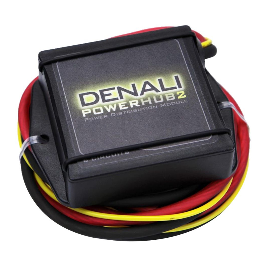
Denali POWERHUB2 - Power Distribution Module Installation Manual
- Installation instructions (2 pages)
Advertisement
Features
- 6 Mini ATC Fused circuits for a total of 30 amps
- Each circuit can be switched or unswitched
- Wiring harness included
- Adhesive Velcro included
Introduction
PLEASE READ BEFORE INSTALLING
TWISTED THROTTLE products should be installed by a qualified, experienced motorcycle technician. If you are unsure of your ability to properly install a product, please have the product installed by your local motorcycle dealer. TWISTED THROTTLE takes no responsibility for damages caused by improper installation.
Medium strength liquid thread-locker (i.e., "Locktite") should be used to secure all screws, bolts, and nuts.
All screws, bolts, and nuts should be checked after driving the first 30 miles (50 km) to ensure that all are tightened to the proper torque.
All screws, bolts, and nuts, including all replacement hardware provided by TWISTED THROTTLE should be tightened to the torque specified in the OEM maintenance manual for your motorcycle. If no torque specifications are provided in the OEM maintenance manual, the following torques may be used:
| M5 | 3.5 ft-lbs (5 Nm) |
| M6 | 6.5 ft-lbs (9 Nm) |
| M8 | 16 ft-lbs (22 Nm) |
| M10 | 32 ft-lbs (43 Nm) |
| M12 | 55 ft-lbs (75 Nm) |
Kit Contents

Wiring Instructions
- Connect the POWERHUB2 to your battery.
Start by connecting the red wire from the POWERHUB2 to the positive terminal of your battery. Connect the black wire from the POWERHUB2 to the negative terminal of your battery. - Tap a switched power source on your motorcycle.
Use the "Posi-Tap" to tap the yellow wire to a switched 12V power source on your motorcycle. A switched power source is any wire that is +12 VDC when you motorcycle is turned on and 0 VDC when your motorcycle is turned off. Refer to your service manual or local mechanic to find a suitable switched power source for you specific motorcycle. On BMW canbus motorcycles, use either the can bus adapter (EC.02350, sold separately), or tap the original BMW power socket positive wire. - Connecting your devices to the POWERHUB2.
Notice that the POWERHUB2 has 6 circuits. Each circuit has an output bus, ground bus, and 2 fuse positions. To connect a device, start by inserting the proper amperage Mini ATC fuse into either the switched or constant fuse position in circuit 1. Then, connect the positive wire from your device to circuit 1 output terminal. Connect the ground wire from your device to the circuit 1 ground bus terminal on the POWERHUB2.
Note: The position of the fuse simply determines whether your device has power when the motorcycle is turned off. The switched fuse position will only allow power to the device when the motorcycle is turned on, while the constant fuse position will allow power to your device even when the motorcycle is turned off.
Wiring Diagram
Note: This drawing is not to scale. Components are enlarged for illustrative purposes only.

POWERHUB2 // Power Distribution Module // ELC.00.30000

Documents / ResourcesDownload manual
Here you can download full pdf version of manual, it may contain additional safety instructions, warranty information, FCC rules, etc.
Download Denali POWERHUB2 - Power Distribution Module Installation Manual
Advertisement

Need help?
Do you have a question about the POWERHUB2 and is the answer not in the manual?
Questions and answers