Advertisement
Table of Contents
Contents
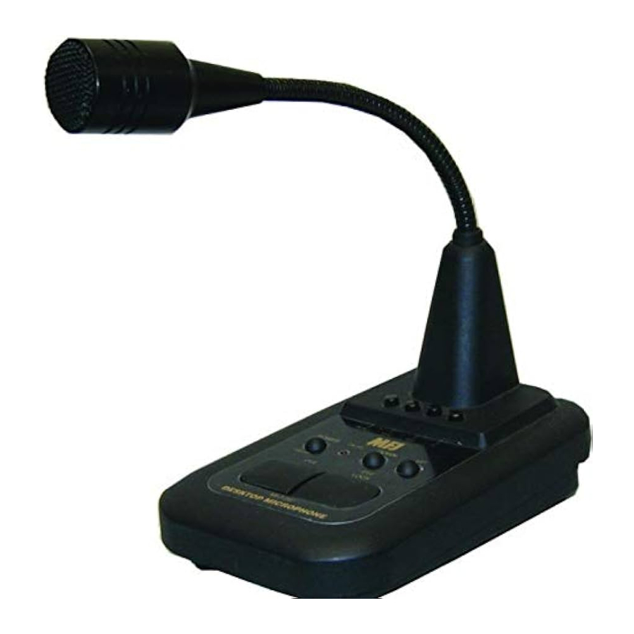
MFJ 297 - Desktop Microphone Manual
Features
- High quality low noise microphone
- Highly sensitive condenser microphone
- Built-in Amplifier
- Voice quality selector switch for FM or SSB use
- Electronic touch switch for PTT and PTT (LOCK) operation
- LED "ON AIR" indicator
- UP & DOWN buttons to change radio-operating frequency from the microphone
- CALL, VFO, MR, and PF function buttons (for Kenwood transceivers)
- Flexible gooseneck

The MFJ-297 is not designed for two transceivers to be connected at the same time. If two transceivers are connected at the same time, serious damage may result to both transceivers.
Specifications
| Wide-band Electric Condenser Microphone |
| 1 – 30 mV (RMS) |
| 500 – 100KΩ |
| 2 AA Batteries |
| 2 mA (RX), 3 mA (TX) |
| 3.93701 (W) X 6.10236 (D) X 1.37795 (H) in ches |
| 0.99208 lbs. |
CONTROLS

- Power Switch. Press switch to turn the power "ON". The "ON AIR" indicator should begin to flash. Press the switch again to turn the power "OFF".
- ONAIR LED Indicator. When the power is "ON", the LED will flash to indicate receive (RX) mode and the LED will be illuminated continuously when in transmit (TX) mode. When the power is "OFF", the LED will not be illuminated.
- PTT Switch. Press the switch for transmit mode and release the switch for receive mode. This can be used for a short QSO. If you have pressed the PTT LOCK switch, the lock can be released by pressing the PTT switch.
- PTT LOCK Switch. Press the switch to lock the microphone in transmit mode. The "ON AIR" LED indicator will remain illuminated after the switch is released. To disable the lock feature, press the PTT switch to return to receive mode.
- UP/DOWN Switches. These switches are for changing the radio frequency up and down. For details, please refer to your transceiver instruction manual.
- Microphone. An electret condenser microphone is used for clear voice quality.
- Special Function Buttons. These buttons allow you remote access to the special features on your transceiver. These buttons are not compatible with all transceivers.
The buttons are as follows:
CALL – Selects the call frequency
VFO – Selects VFO mode for manual tuning
MR – Memory Recall selects preset memory tuning
PF – Activates the Preset Function feature - Microphone Output Connectors. Please use an interconnecting cable that is compatible with your transceiver. Cables are available separately. For ICOM and MFJ transceivers, plug the cable into Microphone Output Connector "A". For Yaesu and Kenwood transceivers, plug the cable into Microphone Output Connector "B".
- FM/SSB Voice Quality Selector Switch. Change the selector switch for the microphone output audio quality for the mode in which you will be operating. In FM mode operation, the output is adjusted to provide a clear voice quality with wide frequency characteristics. In SSB mode operation, the output is adjusted to provide a sharp and crisp voice quality for effective DXing.
- Selector for Output. The switch allows you to select the Microphone Output Connector that is suitable for your transceiver. For ICOM, Yaesu, and MFJ transceivers, the selector switch should be placed in the "A" position. For Kenwood transceivers, the switch should be place in the "B" position.
- Output adjustment Volume. This is factory set to 10 mV RMS output from the microphone. If needed use a 3mm flat head screwdriver to adjust the output to suit your transceiver.
- Battery Cover. Open the battery cover and insert two fresh AA batteries (not included). Be sure to note the polarity markings inside the battery compartment.
Caution
- Please be careful about high SWR of antenna and incomplete grounding. This may cause RF feedback noise and could damage the MFJ-297.
- Please turn off the power after use to extend battery life.
- It is recommended that the batteries be removed from the MFJ-297 for prolonged periods of inactivity.
- Do not place the MFJ-297 in high temperatures and avoid direct sunlight.
- Do not connect more than one transceiver at a time to the MFJ-297. This could damage the transceivers.
Cables for the device
| MFJ Model No. | Compatible Transceivers | Microphone Output Connector | Selector Switch Position |
| MFJ-5397I | ICOM 8-Pin Round | A | A |
| MFJ-5397K | Kenwood 8-Pin Round | B | B |
| MFJ-5397Y | Yaesu 8-Pin Round | B | A |
| MFJ-5397MX | ICOM 8-Pin Modular | A | A |
| MFJ-5397MX | Kenwood 8-Pin Modular | B | B |
| MFJ-5397MY | Yaesu 8-Pin Modular | B | A |
| MFJ-5399 | MFJ | A | A |

A
- No Connect
- PTT GND
- MIC Input
- MIC GND
- PTT
- No Connect
- Frequency Up/Down
- +8VDC
B
- Frequency Up
- +8VDC
- PTT GND
- PTT
- MIC GND
- MIC Input
- No Connect
- Frequency Down
Documents / ResourcesDownload manual
Here you can download full pdf version of manual, it may contain additional safety instructions, warranty information, FCC rules, etc.
Advertisement


Need help?
Do you have a question about the 297 and is the answer not in the manual?
Questions and answers