
Related Manuals for LEGRAND VADDIO RoboTRAK

Summary of Contents for LEGRAND VADDIO RoboTRAK
- Page 1 Complete Manual for the RoboTRAK Presenter Tracking System Document 411-0004-30 Rev. F August 2022...
-
Page 2: Table Of Contents
Contents Overview What's in this Guide Features A Quick Look at the RoboTRAK System Front of the RoboTRAK IR Camera Back of the IR Camera A Quick Look at the Tracking Lanyard Before You Start Selecting the Installation Site Camera Location Camera Placement – Small Room Camera Placement –... - Page 3 Complete Manual for the RoboTRAK Presenter Tracking System Specifying Time Zone and NTP Server Configuring the Tracking System The Tracking Configuration Process About Distance Configuration Files Determining Which Distance Configuration Files to Use Loading the Distance Configuration File Setting the Room Label Information Pairing the Cameras Setting up the IR and Video Camera Lanyard Shots Viewing the Stream from the IR Camera...
- Page 4 Complete Manual for the RoboTRAK Presenter Tracking System Tips for Handling and Storing the Lanyard Telnet Serial Command API Requirements Usage notes Getting More Information Typographical Conventions About Controlling the Video Camera via Telnet Commands to Avoid Camera Commands camera master tracking camera slave1 preset recall camera master ccu camera master led...
-
Page 5: Overview
Overview This manual covers the RoboTRAK IR camera and presenter tracking system: RoboTRAK camera, North America – 999-7270-000B RoboTRAK camera, Europe and UK – 999-7270-001B RoboTRAK camera, Australia and New Zealand – 999-7270-009B Lanyard, North America – 999-7271-000 Lanyard, Europe and UK – 999-7271-001 Lanyard, Australia and New Zealand –... -
Page 6: A Quick Look At The Robotrak System
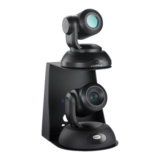
Complete Manual for the RoboTRAK Presenter Tracking System A Quick Look at the RoboTRAK System This section covers the physical features of the RoboTRAK system: IR camera Tracking lanyard The RoboTRAK system requires a video camera as well. You can use any free-standing RoboSHOT camera as the video component of the system. -
Page 7: A Quick Look At The Tracking Lanyard
Complete Manual for the RoboTRAK Presenter Tracking System A Quick Look at the Tracking Lanyard Vaddio recommends purchasing a second lanyard as a spare or for smooth transitions between multiple presenters. A lanyard with a back loop extension is available for presenters whose hair, head covering, or clothing may otherwise cover the lanyard ribbon. -
Page 8: Before You Start
Complete Manual for the RoboTRAK Presenter Tracking System Before You Start Ensure that the room is suitable for the RoboTRAK system, and that all the required elements of the installation are present. This section covers the requirements for a successful installation. Selecting the Installation Site Note Install the cameras with the IR camera directly above the video camera. -
Page 9: Camera Placement - Medium Room
Complete Manual for the RoboTRAK Presenter Tracking System Camera Placement – Medium Room... -
Page 10: Camera Placement - Large Room
Complete Manual for the RoboTRAK Presenter Tracking System Camera Placement – Large Room Lighting and IR Note The RoboTRAK IR camera works best in an IR-sterile environment. Natural lighting and halogen lamps produce enough stray IR to overwhelm the system. If the room has windows, blackout curtains or blinds are required - standard window blinds admit enough IR at the edges to keep the IR camera from identifying the tracking lanyard. - Page 11 Complete Manual for the RoboTRAK Presenter Tracking System This is a shot from the IR stream of a RoboTRAK camera in an IR-sterile room. Other than the presenter's lanyard, the room is dark. This is what you should see when you view the stream from the IR camera.
-
Page 12: Installation
Complete Manual for the RoboTRAK Presenter Tracking System Installation This section covers installing the mount, functional check, and connecting the camera. Don’t Void Your Warranty! Caution This product is for indoor use. Do not install it outdoors or in a humid environment without the appropriate protective enclosure. -
Page 13: The Ir Camera's Default Hostname
Complete Manual for the RoboTRAK Presenter Tracking System The IR Camera's Default Hostname You will need to reach both cameras' web interfaces to do the initial device setup and to configure the system for use. If you do not use the Vaddio Device Controller or Vaddio Deployment Tool to access the IR camera’s web interface, you will need to point your browser to its default hostname. -
Page 14: Connections For Configuring The System
Complete Manual for the RoboTRAK Presenter Tracking System Connections for Configuring the System To configure the system for the room and set up the desired tracking behavior, you will need to view the IP stream from the IR camera. Side-by-side displays of the IR camera stream and the video camera output are strongly recommended. -
Page 15: Installing The Camera Mount
Complete Manual for the RoboTRAK Presenter Tracking System Installing the Camera Mount The RoboTRAK presenter tracking system‘s dual wall mount can be used with Vaddio's Offset Drop- down Ceiling Mount for RoboTRAK, part number 535-2000-045. Contact us if you don’t have the camera mount you need. -
Page 16: Installing The Cameras
Complete Manual for the RoboTRAK Presenter Tracking System Installing the Cameras Note Copy the default hostname from the label on the bottom of the camera, and keep this information in a place where it will be available to anyone who needs to work with the camera's web interface. This information is required to access the camera for initial configuration, or after a factory reset. -
Page 17: Preparing The Tracking Lanyard For Use
Complete Manual for the RoboTRAK Presenter Tracking System Preparing the Tracking Lanyard for Use You will need all the items from the box that the lanyard was shipped in: Lanyard USB charger USB charging cable Ferrite bead Note To ensure compliance with FCC regulations, you must install the ferrite bead as directed in step 1. -
Page 18: Initial Device Set-Up And System Administration Tasks
Complete Manual for the RoboTRAK Presenter Tracking System Initial Device Set-Up and System Administration Tasks Vaddio cameras have a web interface for initial device set-up, administrative control, and operation. When any Vaddio product is shipped from the factory, there is no admin password and the administrative controls are not available. -
Page 19: Initial Device Set-Up Using The Vaddio Deployment Tool
Complete Manual for the RoboTRAK Presenter Tracking System Initial Device Set-Up Using the Vaddio Deployment Tool The Vaddio Deployment Tool simplifies provisioning and system administration for most products, and provides a shortcut to each device's web interface. The screen shots are examples only, and show how to do this for a different product. To complete the initial device set-up with the Vaddio Deployment Tool: 1. -
Page 20: Initial Device Set-Up Using The Vaddio Device Controller
Complete Manual for the RoboTRAK Presenter Tracking System Initial Device Set-Up Using the Vaddio Device Controller The Vaddio Device Controller is a stand-alone appliance for working with Vaddio products' web interfaces. Unlike the Vaddio Deployment Tool, it does not need to be updated to support new products. For detailed instructions on installation and use, refer to the Vaddio Device Controller's manual. -
Page 21: System Administration
Complete Manual for the RoboTRAK Presenter Tracking System System Administration This section covers basic system administration tasks: Security settings Specifying time zone and NTP server These tasks are nearly identical to the corresponding system administration tasks for the video camera. Configuring Access and Other Security Settings ECURITY PAGE The Account Passwords and Web Server areas of the Security page provide basic security for the web... -
Page 22: Assigning A Hostname Or Ip Address
Complete Manual for the RoboTRAK Presenter Tracking System Assigning a Hostname or IP Address ETWORKING PAGE In a network that supports hostname resolution, you can assign each camera a hostname that conforms to the organization's network policies. This is optional; you can continue to use the cameras' default hostnames. -
Page 23: Specifying Time Zone And Ntp Server
Complete Manual for the RoboTRAK Presenter Tracking System Specifying Time Zone and NTP Server ETWORKING PAGE Using automatic NTP updating ensures that the timestamps in the camera's diagnostic log are accurate. Specifying your time zone may make it easier to match logged events with other actions and external events. -
Page 24: Configuring The Tracking System
Complete Manual for the RoboTRAK Presenter Tracking System Configuring the Tracking System Before you start, be sure the lanyard is fully charged and the ring glows blue to indicate it is powered up. You will need: Equipment to view the IP streams from both cameras. A stream viewer application such as VideoLAN VLC Media Player –... -
Page 25: About Distance Configuration Files
Complete Manual for the RoboTRAK Presenter Tracking System About Distance Configuration Files The RoboTRAK camera’s factory default configuration typically delivers good tracking performance for the area 20 to 40 ft. (6.1 to 12.2 m) from the cameras. Most installations use the default distance configuration. -
Page 26: Loading The Distance Configuration File
Complete Manual for the RoboTRAK Presenter Tracking System Loading the Distance Configuration File YSTEM PAGE Do this before you do any set-up or configuration. Loading a configuration will overwrite any configuration changes you have already made. Vaddio provides RoboTRAK room configuration files for common room sizes and layouts. 1. -
Page 27: Pairing The Cameras
Complete Manual for the RoboTRAK Presenter Tracking System Pairing the Cameras AIRING PAGE Notes Load the configuration file of your choice before you pair the cameras. If you plan to assign camera hostnames rather than using the default hostnames, assign them before pairing the cameras. -
Page 28: Setting Up The Ir And Video Camera Lanyard Shots
Complete Manual for the RoboTRAK Presenter Tracking System Setting up the IR and Video Camera Lanyard Shots This phase of RoboTRAK configuration includes: Viewing the IP stream from the RoboTRAK IR camera Viewing video from the video camera Framing the IR camera's lanyard shot Framing the video camera's lanyard shot For the framing tasks and subsequent tuning, someone will need to wear the lanyard and move around in the area where the presenter will normally be. - Page 29 Complete Manual for the RoboTRAK Presenter Tracking System 1. Be sure the lanyard is turned on. Then put it on, or have someone else put it on to act as the presenter. 2. Select Setup mode. The IR camera’s stream shows a white rectangle outline at the center of the image.
-
Page 30: Storing The Video Camera's Lanyard Shot
Complete Manual for the RoboTRAK Presenter Tracking System Storing the Video Camera's Lanyard Shot RACKING PAGE IDEO AMERA HOT TAB Notes You must store the IR camera's lanyard shot before you do this task. Be sure your presenter is in the same place they were for the IR camera’s lanyard shot. The video camera does not zoom while tracking. - Page 31 Complete Manual for the RoboTRAK Presenter Tracking System To compose and store the video camera's lanyard shot: 1. Change to Setup Mode if it is not already selected. 2. Have the presenter stay in exactly same place as for the IR lanyard shot. 3.
-
Page 32: Testing And Fine-Tuning
Complete Manual for the RoboTRAK Presenter Tracking System Testing and Fine-Tuning RACKING PAGE Basic configuration and tuning – pairing the cameras and setting up the lanyard shots – is enough to make the system work. As the IR camera tracks the lanyard, the software drives the video camera based on the IR camera's motion. -
Page 33: Tuning Cheat Sheet
Complete Manual for the RoboTRAK Presenter Tracking System Ask the presenter to move around in the presentation area, and observe the video camera's tracking behavior. What needs improvement? Tuning Cheat Sheet Many adjustments affect each other, so the tuning process may require some experimenting. Tracking behavior What it means How to fix it... -
Page 34: Setting The Ir Camera's Home Position
Complete Manual for the RoboTRAK Presenter Tracking System Setting the IR Camera's Home Position RACKING PAGE RACKING IMITS TAB As with RoboSHOT cameras, you can set a custom home position for the IR camera. It returns to this position when it is not tracking. A typical home position might be a shot of the presenter's podium or lectern. -
Page 35: Setting The Lanyard Searching Behaviors
Complete Manual for the RoboTRAK Presenter Tracking System Setting the Lanyard Searching Behaviors RACKING PAGE RACKING IMITS TAB AND DVANCED TAB When the IR camera does not detect the lanyard for a specified length of time, it begins searching. If it does not find the lanyard, it moves to its home position. -
Page 36: Setting The Presenter Area And Search Area
Complete Manual for the RoboTRAK Presenter Tracking System Setting the Presenter Area and Search Area RACKING PAGE RACKING IMITS TAB By default, the IR camera tracks the presenter anywhere within 90° to either side of its straight-ahead (0°) position. This area is defined by the tracking pan limits. If the IR camera stops detecting the lanyard, it searches a smaller area, defined by the search pan limits. -
Page 37: Adjusting Agc Gain
Complete Manual for the RoboTRAK Presenter Tracking System To adjust the IR Tracking Camera Pan Limits or Lanyard Search Pan Limits: 1. Use the pan left and pan right arrows to move the camera to the desired pan limit. The camera position dot moves along the pan limit indicators. -
Page 38: Setting The Tracking Speed: Speed Scaler
Complete Manual for the RoboTRAK Presenter Tracking System Setting the Tracking Speed: Speed Scaler RACKING PAGE DVANCED TAB The speed scaler controls how quickly the video camera responds when the IR camera starts moving. The default value is 0.5 second, which works well for wide shots. For tighter shots, or in cases where the presenter will get closer to the camera, you may need to reduce this value to keep the presenter in the frame. -
Page 39: Adjusting The Video Camera Window Width
Complete Manual for the RoboTRAK Presenter Tracking System Adjusting the Video Camera Window Width RACKING PAGE DVANCED TAB People move around as they give their presentations. The system should accommodate natural gestures and body language without moving, and track only when the presenter is moving through the room. The video camera window width determines the distance that the presenter can move before the system starts following. -
Page 40: Dealing With Stray Ir
Complete Manual for the RoboTRAK Presenter Tracking System Dealing with Stray IR RACKING PAGE RACKING IMITS AND DVANCED TABS The RoboTRAK system is designed for environments without stray IR, but tuning can compensate for a limited amount of certain types of stray IR. The IR camera's web interface provides adjustments to compensate for IR interference. - Page 41 Complete Manual for the RoboTRAK Presenter Tracking System Tracking page, Tracking Limits tab: Mask top and bottom areas, change pan limits Tracking page, Advanced tab: Adjust brightness threshold and max bright pixels, mask top and bottom areas...
-
Page 42: Configuring The Video Camera
Complete Manual for the RoboTRAK Presenter Tracking System Configuring the Video Camera You will need to configure the video camera as well as the IR camera. Configuration options vary somewhat, depending on the camera. Refer to the video camera's manual for configuration tasks.Manuals are available on the product pages of the Vaddio website. -
Page 43: Setting Up Macros And Triggers
Complete Manual for the RoboTRAK Presenter Tracking System Setting up Macros and Triggers ONTROL EVICES PAGE Macros are sequences of commands. Refer to the Telnet Serial Command API section for a full list of commands. Triggers register events or state changes that can be associated with macros, to make them run. The RoboTRAK camera provides software triggers that allow you to add operator controls, such as defining the buttons on a conference room touch-screen. -
Page 44: Writing And Editing Macros
Complete Manual for the RoboTRAK Presenter Tracking System Writing and Editing Macros ONTROL EVICES PAGE ACROS TAB To edit or define a macro: 1. Select the Edit button associated with an existing macro, or enter a name for a new macro in the Macro Editor's Name field. -
Page 45: Assigning Macros To Triggers
Complete Manual for the RoboTRAK Presenter Tracking System Assigning Macros to Triggers ONTROL EVICES PAGE RIGGERS TAB A trigger may be associated with a macro that runs when the trigger is on, one that runs when the trigger is off, or one of each. To assign a macro to a trigger: Do at least one of these things: Select a macro in the Execute Macro on Enter field. -
Page 46: Testing Triggers
Complete Manual for the RoboTRAK Presenter Tracking System Testing Triggers ONTROL EVICES PAGE Just as it can be helpful to test macros when you write them, it can also be helpful to test triggers when you assign macros to them. The Trigger Testing section is available from both tabs of the Control Devices page. -
Page 47: System Maintenance
Complete Manual for the RoboTRAK Presenter Tracking System System Maintenance This section covers basic system maintenance tasks: Exporting and importing configurations Downloading and installing firmware updates These tasks are nearly identical to the corresponding tasks for the video camera. Exporting the Configuration YSTEM PAGE Now that you have everything working exactly the way you want it to, save your work. -
Page 48: Installing Firmware Updates
Complete Manual for the RoboTRAK Presenter Tracking System Installing Firmware Updates YSTEM PAGE The RoboTRAK IR camera and the RoboSHOT video camera use the same procedure for firmware updates. 1. Locate the link to download the camera's firmware update from the website, and select it. It's with the link for the release notes. -
Page 49: Operating And Presenting With The Robotrak System
Complete Manual for the RoboTRAK Presenter Tracking System Operating and Presenting with the RoboTRAK System The system can operate in tracking mode, or you can control the video camera as you would do with any PTZ camera. How It Works To present with the system in tracking mode, you wear the lanyard, which is an IR source that the IR camera can track. -
Page 50: Presentation Controls
Complete Manual for the RoboTRAK Presenter Tracking System Presentation Controls The operator’s page of the web interface provides presentation controls. Your room AV system may provide this page. It includes: Tracking on/off control – Enables or disables tracking. When tracking is on and the lanyard is on, the IR camera follows the lanyard if the lanyard is within the camera’s tracking area. -
Page 51: Lanyard Status Light
Complete Manual for the RoboTRAK Presenter Tracking System Lanyard Status Light The ring on the lanyard's center button is a status light that aims the light to the sides, so you can see it while wearing the lanyard. Blue – The lanyard is active; the IR LEDs in the ribbon are on and can be tracked Blinking yellow –... -
Page 52: Quick Reference: How The Cameras Behave
Complete Manual for the RoboTRAK Presenter Tracking System Quick Reference: How the Cameras Behave If the cameras are doing this... It means... Both cameras are pointed in the The system is ready to track. same direction. They are not To start tracking, turn on your lanyard by pressing the center button. moving. - Page 53 Complete Manual for the RoboTRAK Presenter Tracking System Telnet Serial Command API The Vaddio Telnet command API allows an external device such as an AMX or Crestron presentation system to control the camera. It is also used for writing macros. Requirements Telnet must be enabled on the Security page of the device's web interface.
- Page 54 Complete Manual for the RoboTRAK Presenter Tracking System Camera Commands The following camera commands are available: camera master ccu camera master led camera slave1 preset recall camera master tracking camera master standby camera master standby config peripheral These commands affect only the specified camera. camera master tracking Stop or start tracking mode.
- Page 55 Complete Manual for the RoboTRAK Presenter Tracking System camera slave1 preset recall Recalls the RoboTRAK system's video camera to the specified preset. The video camera only responds to this command if it has stored the specified preset. When the video camera's presets are accessed via the IR camera, it moves to the preset but the IR camera continues to track.
- Page 56 Complete Manual for the RoboTRAK Presenter Tracking System camera master led Set or change the behavior of the IR camera’s status light. To set the behavior of the video camera’s status light, you will need to send the camera led command directly to the video camera, or change this setting in its web interface.
- Page 57 Complete Manual for the RoboTRAK Presenter Tracking System camera master standby config peripheral Returns or sets the standby behavior for the RoboTRAK system's video camera. Synopsis camera master standby config peripheral [ get | on | off | toggle ] Options Returns the current standby configuration for the video camera.
- Page 58 Complete Manual for the RoboTRAK Presenter Tracking System streaming settings get Returns the IP streaming settings for the IR camera. Go to the Streaming page of the camera’s web interface to manage these settings. Synopsis streaming settings get > streaming settings get Example IP Custom_Frame_Rate IP Custom_Resolution...
- Page 59 Complete Manual for the RoboTRAK Presenter Tracking System trigger Runs the macro associated with the specified trigger state. The macro must exist, and it must be possible to execute it successfully. For example, if the macro sends the video camera to a preset, the preset must be stored on the video camera. Synopsis trigger <...
- Page 60 Complete Manual for the RoboTRAK Presenter Tracking System Maintenance and Troubleshooting Commands The following commands are available for maintenance and troubleshooting: network ping version camera master recalibrate camera master sensor get system reboot system factory-reset The network, system, and version commands work for any Vaddio camera you send them to. The camera master commands are for the IR camera only.
- Page 61 Complete Manual for the RoboTRAK Presenter Tracking System camera master sensor get Returns information that identifies which distance configuration files to use with your camera. Synopsis camera master sensor get > camera master sensor get Example “Hi_SC210” > system reboot Reboots the system either immediately or after the specified delay.
- Page 62 Complete Manual for the RoboTRAK Presenter Tracking System system factory-reset Gets or sets the factory reset status. When the factory reset status is on, the system resets to factory defaults on reboot. Synopsis system factory-reset { get | on | off} Options Returns the camera's current factory reset status.
- Page 63 Complete Manual for the RoboTRAK Presenter Tracking System Telnet Information and Session Management Commands The following commands are available for Telnet help and session management: history help exit help Displays an overview of the CLI syntax. Synopsis help help Example history Returns the most recently issued commands from the current Telnet session.
- Page 64 Complete Manual for the RoboTRAK Presenter Tracking System Troubleshooting and Care Stuff happens – we get it. When the system doesn't act as you expect, check these things first: For details on camera interactions during normal use, see How the Cameras Behave.
- Page 65 Complete Manual for the RoboTRAK Presenter Tracking System Corrective Actions YSTEM PAGE IRMWARE TAB To correct a motor calibration fault: The RoboTRAK IR camera's pan and tilt motors can occasionally go out of calibration – for example, if the camera is jostled during operation. To recalibrate the motors, select Pan-Tilt Reset. This button is also available on the operator’s page of the web interface.
- Page 66 Complete Manual for the RoboTRAK Presenter Tracking System Getting Help ELP PAGE If you can't resolve an issue using your superior troubleshooting skills (and maybe the Troubleshooting information in this manual), we are here to help. You’ll find information for contacting Vaddio Technical Support on the Help page. Your technical support representative may ask you to download the event log from the Diagnostics page.
- Page 67 Complete Manual for the RoboTRAK Presenter Tracking System Operation, Storage, and Care For smears or smudges on any component of the system, wipe with a clean, soft cloth. Use a lens cleaner on the lens. Do not use any abrasive chemicals. Keep this system away from food and liquids.
- Page 68 cheat sheet 29, 36, 48 camera behavior 48 Index IR mitigation 36 tuning 29 cleaning 63 command history 59 accessing the video camera's web commands 52 interface 23 camera 52 additional products required 2 communicating with the IR camera 9 adjustments 28-37 compatibility, browsers 14 home position 30...
- Page 69 Complete Manual for the RoboTRAK Presenter Tracking System hostname 4, 9, 18, 23 limits 32-33, 37 assigning 18 search 32-33 default 4, 9 tracking 32-33 HTTP, enabling 17 location of the camera 4-6 HTTPS 17 locations of connectors 2 SSL certificate 17 low-power (standby) state 52 idle position 30 macros 39-41...
- Page 70 Complete Manual for the RoboTRAK Presenter Tracking System power on/power off 12 settings, default, restoring 58 precautions 3, 8, 48 setup mode 25 for handling the lanyard 3, 48 shelf, camera mount 11 for operating the system 8 small room layout 4 presentation, starting 45 solving problems 60 presenter's style 26...
- Page 71 Complete Manual for the RoboTRAK Presenter Tracking System testing 40, 42 web interface 16-19, 22-24, 27-28, 30-35, 37-44, 61-62 macros 40 accessing 16, 26 triggers 42 Control Devices page 39-42 theory of operation 45 Diagnostics page 62 third-party control 49, 52 Help page 62 time to search 31 Networking page 18-19...
- Page 72 · Phone 800.572.2011 / +1.763.971.4400 · Fax +1.763.971.4464 · Email av.vaddio.techsupport@legrand.com· Vaddio is a registered trademark of Legrand AV Inc. All other brand names or marks are used for identification purposes and are trademarks of their respective owners. All patents are protected under existing designations.
Need help?
Do you have a question about the VADDIO RoboTRAK and is the answer not in the manual?
Questions and answers