Table of Contents
Advertisement
Quick Links
OPERATION & SAFETY
INSTRUCTIONS
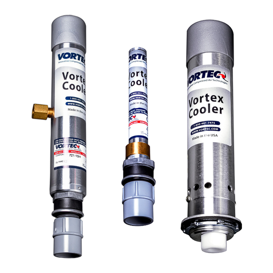
VORTEX COOLERS
I M P O R T A N T
Please read all instructions BEFORE attempting to use this product
10125 Carver Road, Cincinnati, OH 45242
Phone: 513-891-7474 • Fax: 513-891-4092
Toll Free: 800-441-7475
www.vortec.com • techsupport@vortec.com
Advertisement
Table of Contents


Need help?
Do you have a question about the 727 and is the answer not in the manual?
Questions and answers