Table of Contents
Advertisement
Quick Links
Advertisement
Table of Contents

Related Manuals for Peak PCAN-GPS

Summary of Contents for Peak PCAN-GPS
- Page 1 PCAN-GPS User Manual User Manual 2.1.1 © 2023 PEAK-System Technik GmbH...
-
Page 2: Imprint
IPEH-002110 Imprint PCAN is a registered trademark of PEAK-System Technik GmbH. microSD™ is a trademark or registered trademark of SD-3C, LLC in the United States of America, other countries, or both. All other product names in this document may be the trademarks or registered trademarks of their respective companies. -
Page 3: Table Of Contents
4.2 SMA Antenna Connector 4.3 microSD™ Slot (internal) 5 Operation 5.1 Starting PCAN-GPS 5.2 Status LEDs 5.3 Sleep Mode 5.4 Wake-up 6 Creating Own Firmware 6.1 Library 7 Firmware Upload 7.1 System Requirements Contents PCAN-GPS User Manual 2.1.1 © 2023 PEAK-System Technik GmbH... - Page 4 8 Technical Data Appendix A CE Certificate Appendix B UKCA Certificate Appendix C Dimension Drawing Appendix D CAN-Messages of the Demo Firmware D.1 CAN Messages from the PCAN-GPS D.2 CAN Messages to the PCAN-GPS Appendix E Data Sheets Appendix F Disposal Contents PCAN-GPS User Manual 2.1.1...
-
Page 5: Introduction
C and C++ and is then transferred to the module via CAN. Various programming examples facilitate the implementation of own solutions. On delivery, the PCAN-GPS is provided with a demo firmware that transmits the raw data of the sensors periodically on the CAN bus. The source code of the demo firmware as well as further programming examples are included in the scope of supply. -
Page 6: Properties At A Glance
Voltage supply from 8 to 30 V Extended operating temperature range from -40 to +85 °C (with exception of the button cell) New firmware can be loaded via CAN interface 1 Introduction PCAN-GPS User Manual 2.1.1 © 2023 PEAK-System Technik GmbH... -
Page 7: Scope Of Supply
1.2 Scope of Supply PCAN-GPS in plastic casing with Mating connector: Phoenix Contact FMC 1.5/10-ST-3.5 - 1952348 External antenna for satellite reception Download Windows development package with: GCC ARM Embedded Flash program Programming examples Manual in PDF format 1.3 Prerequisites for Operation... -
Page 8: Description Of The Sensors
GNSS receiver must be switched. For a faster position fix after turning on the PCAN-GPS, the internal RTC and the internal backup RAM can be supplied by the button cell. This requires a hardware modification (see section 3.2 Buffer Battery for GNSS). -
Page 9: Gyroscope
Z: yaw X: roll Y: pitch Gyroscope axes in relation to the PCAN-GPS casing The covered rotation angle can be determined by integration over time. There are two sensor-internal filters for limitation and damping of output values. They are implemented by configurable high-pass and low-pass. -
Page 10: Acceleration And Magnetic Field Sensor
The acceleration and magnetic field sensor Bosch Sensortec BMC050 is used to determine the position in a magnetic field (such as the earth's magnetic field) and the acceleration along three axes. 2 Description of the Sensors PCAN-GPS User Manual 2.1.1 © 2023 PEAK-System Technik GmbH... - Page 11 Axes of the acceleration and magnetic field sensor in relation to the PCAN-GPS casing There are three configurable control lines to adjust the function to the respective application: Data Ready MAG Interrupt_MAG Interrupt_ACC1 Interrupt_ACC2 is not connected to the microcontroller. All connected interrupt lines of the sensor are provided with pull-up resistors.
- Page 12 Fast compensation: The correction value is calculated from the average of 16 measurements and the target value. Manual compensation: The user specifies a correction value. Inline calibration: The calculated correction value is stored in the EEPROM. 2 Description of the Sensors PCAN-GPS User Manual 2.1.1 © 2023 PEAK-System Technik GmbH...
-
Page 13: Hardware Configuration
ID is conceivable here. For a firmware update via CAN, the PCAN-GPS module is identified by a 3-bit ID which is determined by solder jumpers. A bit is set (1) when the corresponding solder field is open (default setting: ID 7, all solder fields open). - Page 14 Activate coding solder bridges: Risk of short circuit! Soldering on the PCAN-GPS may only be performed by qualified electrical engineering personnel. Attention! Electrostatic discharge (ESD) can damage or destroy components on the card. Take precautions to avoid ESD. 1. Unscrew the two screws.
-
Page 15: Buffer Battery For Gnss
The receiver for navigation satellites (GNSS) needs about half a minute until the first position fix after switching on the PCAN-GPS module. To shorten this period, the button cell can be used as a buffer battery for a quick start of the GNSS receiver. - Page 16 Solder field JP6 on the circuit board 5. Put the housing cover back in place according to the recess of the antenna connection. 6. Screw the two screws back into their original positions. 3 Hardware Configuration PCAN-GPS User Manual 2.1.1 © 2023 PEAK-System Technik GmbH...
-
Page 17: Connectors
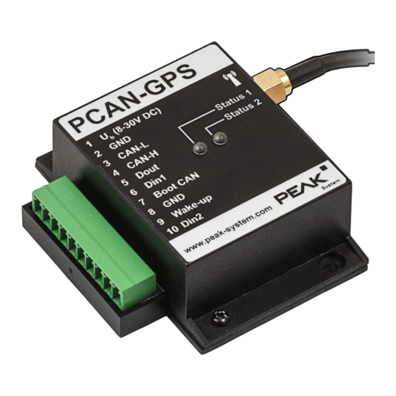
4 Connectors PCAN-GPS with 10 connector pins and 2 status LEDs 4 Connectors PCAN-GPS User Manual 2.1.1 © 2023 PEAK-System Technik GmbH... -
Page 18: Spring Terminal Strip
Digital input, High-active (internal pull-down), inverting Boot CAN CAN bootloader activation, High-active Ground Wake-up External wake-up signal, High-active, e.g. car terminal 15 DIn2 Digital input, High-active (internal pull-down), inverting 4 Connectors PCAN-GPS User Manual 2.1.1 © 2023 PEAK-System Technik GmbH... -
Page 19: Sma Antenna Connector
3.3 V with at most 50 mA can be switched through the GNSS receiver. The scope of supply of the PCAN-GPS provides an active antenna that is suitable for the navigation satellite systems GPS and GLONASS. -
Page 20: Operation
(see section 4.1 Spring Terminal Strip). The firmware in the flash memory is subsequently run. At delivery, the PCAN-GPS is provided with a demo firmware. At a CAN bit rate of 500 kbit/s, it periodically transmits the raw values determined by the sensors. In Appendix D CAN-Messages of the Demo Firmware is a list of the used CAN messages. -
Page 21: Wake-Up
5.4 Wake-up If the PCAN-GPS is in sleep mode, a wake-up signal will be required for the device to turn on again. The following subsections show the possibilities. -
Page 22: Creating Own Firmware
6 Creating Own Firmware With the help of the development package, you can program your own application-specific firmware for PEAK-System programmable hardware products. For each supported product, examples are included. System requirements: Computer with operating system Windows 11 (x64), 10 (x86/x64) - Page 23 7. Prepare your hardware for firmware upload like described in section 7.2 Preparing Hardware. 8. Use the PEAK-Flash tool to upload your firmware to the PCAN-GPS via CAN. The tool is either started via the menu Terminal > Run Task > Flash Device or from the subdirectory of the development package.
-
Page 24: Library
(* stands for version number), a binary file. You can access all resources of the PCAN-GPS by means of this library. The library is documented in the header files (*.h) which are located in the inc subdirectory of each example directory. -
Page 25: Firmware Upload
CAN bus with 120 Ohm each. Operating system Windows 11 (x64), 10 (x86/x64) If you want to update several PCAN-GPS modules on the same CAN bus with new firmware, you must assign an ID to each module. See section 3.1 Coding Solder Jumpers. -
Page 26: Firmware Transfer
Pay attention to the proper termination of the CAN cabling (2 x 120 Ohm). 4. Reconnect the power supply. Due to the High level at the Boot connection, the PCAN-GPS starts the CAN bootloader. This can be determined by the status LEDs: Status... - Page 27 Transfer firmware with PEAK-Flash: The software PEAK-Flash is included in the development package, which can be downloaded via the following link: www.peak-system.com/quick/DLP-DevPack 1. Open the zip file and extract it to your local storage medium. 2. Run the PEAK-Flash.exe. The main window of PEAK-Flash appears.
- Page 28 6. In the drop-down menu Bit rate, select the nominal bit rate 500 kbit/s. 7. Click on Detect. In the list, the PCAN-GPS appears together with the Module ID and Firmware version. If not, check whether a proper connection to the CAN bus with the appropriate nominal bit rate exists.
- Page 29 10. Select the corresponding file (*.bin). 11. Click Next. The Ready to Flash dialog appears. 12. Click Start to transfer the new firmware to the PCAN-GPS. The Flashing dialog appears. 13. After the process is complete, click Next. 14. You can exit the program.
-
Page 30: Technical Data
60 µA Button cell for RTC Type CR2032, 3 V, 220 mAh, (and GNSS if required) operating time without power supply of the PCAN-GPS approx. 570 days Note: Observe the operating temperature range for used button cell. Connectors Spring terminal strip 10-pole, 3.5 mm pitch... - Page 31 (TTFF) Accuracy of the position GPS: 2.5 m values GPS with SBAS: 2 m GLONASS: 4 m Supply for active antenna 3.3 V, max. 50 mA, switchable 8 Technical Data PCAN-GPS User Manual 2.1.1 © 2023 PEAK-System Technik GmbH...
- Page 32 Sleep (2 mA), Power-down (5 µA) Acceleration and Magnetic Field Sensor Type Bosch Sensortec BMC050 Connection to microcontroller SPI Accelerometer Measuring ranges ±2, ±4, ±8, ±16 G Data format 10 bits, two's complement 8 Technical Data PCAN-GPS User Manual 2.1.1 © 2023 PEAK-System Technik GmbH...
- Page 33 ≤ 2.2 V Internal resistance 133 kΩ Digital Output Count 1 (terminal 5) Type Low-side driver Max. voltage 30 V Max. current 0.5 A Short-circuit current 1.5 A 8 Technical Data PCAN-GPS User Manual 2.1.1 © 2023 PEAK-System Technik GmbH...
- Page 34 RoHS 2 EU Directive 2011/65/EU (RoHS 2) EU Directive 2015/863/EU (amended list of restricted substances) DIN EN IEC 63000:2019-05;VDE 0042-12:2019-05 EU Directive 2014/30/EU DIN EN 61326-1:2013-07; VDE 0843-20-1:2013-07 8 Technical Data PCAN-GPS User Manual 2.1.1 © 2023 PEAK-System Technik GmbH...
-
Page 35: Appendix A Ce Certificate
Electrical equipment for measurement, control and laboratory use - EMC requirements - Part 1: General requirements (IEC 61326-1:2020); German version of EN IEC 61326-1:2021 Darmstadt, 19 January 2023 Uwe Wilhelm, Managing Director Appendix A CE Certificate PCAN-GPS User Manual 2.1.1 © 2023 PEAK-System Technik GmbH... -
Page 36: Appendix B Ukca Certificate
Electrical equipment for measurement, control and laboratory use - EMC requirements - Part 1: General requirements (IEC 61326-1:2020); German version of EN IEC 61326-1:2021 Darmstadt, 19 January 2023 Uwe Wilhelm, Managing Director Appendix B UKCA Certificate PCAN-GPS User Manual 2.1.1 © 2023 PEAK-System Technik GmbH... -
Page 37: Appendix C Dimension Drawing
Appendix C Dimension Drawing Appendix C Dimension Drawing PCAN-GPS User Manual 2.1.1 © 2023 PEAK-System Technik GmbH... -
Page 38: Appendix D Can-Messages Of The Demo Firmware
PCAN-GPS at delivery. They list the CAN messages that, on the one hand, are transmitted periodically by the PCAN-GPS (600h to 640h) and, on the other hand, can be used to control the PCAN-GPS (650h to 657h). The CAN messages are sent in Intel format. -
Page 39: Can Messages From The Pcan-Gps
D.1 CAN Messages from the PCAN-GPS CAN ID Start bit Bit count Identifier Values 600h BMC_Acceleration (Cycle time 75 ms) Acceleration_X Conversion to mG: raw value * 3.91 Acceleration_Y Acceleration_Z Temperature Conversion to °C: raw value * 0.5 + 24... - Page 40 Floating-point number unit: km/h 622h GPS_PositionLongitude (Cycle time 100 ms) GPS_Longitude_Minutes Floating-point number GPS_Longitude_Degree GPS_IndicatorEW 0 = INIT 69 = East 87 = West Appendix D CAN-Messages of the Demo Firmware PCAN-GPS User Manual 2.1.1 © 2023 PEAK-System Technik GmbH...
- Page 41 Floating-point number GPS_HDOP 626h GPS_Delusions_B (Cycle time 100 ms) GPS_VDOP Floating-point number 627h GPS_DateTime (Cycle time 100 ms) UTC_Year UTC_Month UTC_DayOfMonth UTC_Hour UTC_Minute UTC_Second Appendix D CAN-Messages of the Demo Firmware PCAN-GPS User Manual 2.1.1 © 2023 PEAK-System Technik GmbH...
- Page 42 0 = Monday 1 = Tuesday 2 = Wednesday 3 = Thursday 4 = Friday 5 = Saturday 6 = Sunday RTC_DayOfMonth RTC_Month RTC_Year Appendix D CAN-Messages of the Demo Firmware PCAN-GPS User Manual 2.1.1 © 2023 PEAK-System Technik GmbH...
-
Page 43: Can Messages To The Pcan-Gps
D.2 CAN Messages to the PCAN-GPS CAN ID Start bit Bit count Identifier Values 650h Out_IO (1 Byte) Dout_Set GPS_SetPower 651h Out_PowerOff (1 Byte) Device_PowerOff 652h Out_Gyro (1 Byte) Gyro_SetScale 0 = ±250 °/s 1 = ±500 °/s 2 = ±2000 °/s... - Page 44 657h Out_Acc_FastCalibration (4 Bytes) Acc_SetCalibTarget_X 0 = 0 G 1 = +1 G Acc_SetCalibTarget_Y 2 = -1 G Acc_SetCalibTarget_Z Acc_StartFastCalib Appendix D CAN-Messages of the Demo Firmware PCAN-GPS User Manual 2.1.1 © 2023 PEAK-System Technik GmbH...
-
Page 45: Appendix E Data Sheets
Appendix E Data Sheets The data sheets of components of the PCAN-GPS are enclosed to this document (PDF files). You can download the current versions of the data sheets and additional information from the manufacturer websites. Antenna taoglas Ulysses AA.162: PCAN-GPS_UserManAppendix_Antenna.pdf... -
Page 46: Appendix F Disposal
Appendix F Disposal The PCAN-GPS and the battery it contains must not be disposed of in household waste. Remove the battery and dispose of the battery and the PCAN-GPS properly in accordance with local regulations. The following battery is included in the PCAN-GPS: 1 x button cell CR2032 3.0 V...
Need help?
Do you have a question about the PCAN-GPS and is the answer not in the manual?
Questions and answers