Table of Contents
Advertisement
Quick Links
Advertisement
Table of Contents

Related Manuals for Asus 90MB1D20-M0EAY0


Summary of Contents for Asus 90MB1D20-M0EAY0
- Page 1 PRIME Z790M-PLUS D4...
- Page 2 Product warranty or service will not be extended if: (1) the product is repaired, modified or altered, unless such repair, modification of alteration is authorized in writing by ASUS; or (2) the serial number of the product is defaced or missing.
-
Page 3: Table Of Contents
Turning off the computer ................ 2-20 Chapter 3: BIOS and RAID Support Knowing BIOS .................... 3-1 BIOS setup program .................. 3-2 ASUS EZ Flash 3 ..................3-3 ASUS CrashFree BIOS 3................3-4 RAID configurations .................. 3-5 Appendix Notices ........................A-1 Warranty ........................ -
Page 4: Safety Information
Safety information Electrical safety • To prevent electrical shock hazard, disconnect the power cable from the electrical outlet before relocating the system. • When adding or removing devices to or from the system, ensure that the power cables for the devices are unplugged before the signal cables are connected. If possible, disconnect all power cables from the existing system before you add a device. -
Page 5: About This Guide
Refer to the following sources for additional information and for product and software updates. ASUS website The ASUS website (www.asus.com) provides updated information on ASUS hardware and software products. Optional documentation Your product package may include optional documentation, such as warranty flyers, that may have been added by your dealer. -
Page 6: Prime Z790M-Plus D4 Specifications Summary
Supports Intel Turbo Boost Technology 2.0 and Intel Turbo Boost Max ® ® Technology 3.0** * Refer to www.asus.com for CPU support list. ** Intel Turbo Boost Max Technology 3.0 support depends on the CPU types. ® Chipset Intel Z790 Chipset ®... - Page 7 PRIME Z790M-PLUS D4 specifications summary Rear USB (Total 8 ports) 1 x USB 3.2 Gen 2x2 port (1 x USB Type-C ® 1 x USB 3.2 Gen 2 port (1 x Type-A) 4 x USB 3.2 Gen 1 ports (4 x Type-A) 2 x USB 2.0 ports (2 x Type-A) Front USB (Total 7 ports) 1 x USB 3.2 Gen 1 connector (supports USB Type-C...
- Page 8 1 x SPI TPM header (14-1pin) 1 x 20-3 pin System Panel header with Chassis intrude function 1 x Thunderbolt™ (USB4 ) header ® ASUS 5X PROTECTION III - DIGI+ VRM (- Digital power design with DrMOS) - LANGuard - Overvoltage Protection - SafeSlot Core+...
- Page 9 Operating System Windows 11, Windows 10 64-bit ® ® mATX Form Factor Form Factor 9.6 inch x 9.6 inch (24.4 cm x 24.4 cm) Specifications are subject to change without notice. Please refer to the ASUS website for the latest specifications.
-
Page 10: Package Contents
Package contents Check your motherboard package for the following items. Motherboard 1 x PRIME Z790M-PLUS D4 motherboard Cables 2 x SATA 6Gb/s cables 1 x I/O Shield 2 x Screw packages for M.2 SSD* Miscellaneous * The package including 2 screws and 1 nut is for installing an M.2 WIFI module into the M.2 WIFI slot and an M.2 SSD module into the M.2_2 slot. -
Page 11: Chapter 1: Product Introduction
Chapter 1: Product Introduction Product Introduction Before you proceed Take note of the following precautions before you install motherboard components or change any motherboard settings. • Unplug the power cord from the wall socket before touching any component. • Before handling components, use a grounded wrist strap or touch a safely grounded object or a metal object, such as the power supply case, to avoid damaging them due to static electricity. -
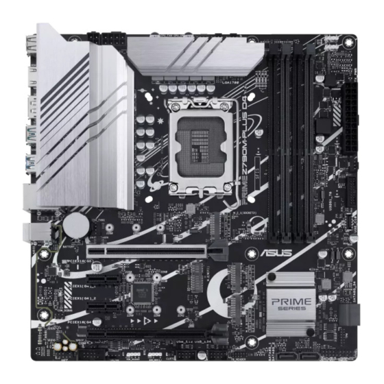
Page 12: Motherboard Layout
Motherboard layout 24.4cm(9.6in) ADD_GEN 2_2 USB_1112 CPU_FAN AIO_PUMP ADD_GEN 2_3 CPU_OPT ATX_12V_2 ATX_12V_1 DIGI+ HDMI 1442K U32G2_9 U32G2X2_C1 U32G1_56 LGA1700 LAN_U32G1_34 BATTERY AUDIO 2280 2260 2242 CHA_FAN1 PCIEX16(G5) 2230 PCIEX1(G4)_1 2280 2260 Ethernet Super Intel ® Z790 PCIEX1(G4)_2 COM_DEBUG 2280 2260 2242 128Mb... - Page 13 Layout contents Page 1. CPU socket 2. DIMM slots 3. Expansion slots 4. Fan and Pump headers 5. Power connectors 6. M.2 slots (SOCKET 3) 1-10 7. SATA 6Gb/s ports 1-11 8. USB 3.2 Gen 1 Type-C Front Panel connector 1-12 ®...
- Page 14 Contact your retailer immediately if the PnP cap is missing, or if you see any damage to the PnP cap/socket contacts/motherboard components. ASUS will shoulder the cost of repair only if the damage is shipment/ transit-related.
- Page 15 DIMM slots The motherboard comes with Dual Inline Memory Modules (DIMM) slots designed for DDR4 (Double Data Rate 4) memory modules. A DDR4 memory module is notched differently from a DDR, DDR2, or DDR3 module. DO NOT install a DDR, DDR2, or DDR3 memory module to the DDR4 slot. Recommended memory configurations DIMM_A1 DIMM_A2...
- Page 16 (D/C) from the same vendor. Check with the vendor to get the correct memory modules. • Visit the ASUS website for the latest QVL. Chapter 1: Product Introduction...
- Page 17 Expansion slots Unplug the power cord before adding or removing expansion cards. Failure to do so may cause you physical injury and damage motherboard components. PCIEX16(G5) PCIEX16(G4) Please refer to the following tables for the recommended VGA configuration and Hyper M.2 configuration.
- Page 18 Additional PCIe bifurcation and M.2 settings for RAID function are also supported when a Hyper M.2 x16 series card is installed. • For full details on the PCIe bifurcation, you may visit the support site at https://www.asus.com/support/FAQ/1037507/. • The Hyper M.2 x16 series card is sold separately. •...
- Page 19 Power connectors These Power connectors allow you to connect your motherboard to a power supply. The power supply plugs are designed to fit in only one orientation. Find the proper orientation and push down firmly until the power supply plugs are fully inserted. ATX_12V_2 ATX_12V_1 PIN 1...
- Page 20 M.2 slots The M.2 slots allow you to install M.2 devices such as M.2 SSD modules. M.2_1(SOCKET3) M.2_2(SOCKET3) M.2_3(SOCKET3) Intel and 12 Gen processors: • ® - M.2_1 supports PCIe 4.0 x4 mode M Key design and type 2242/2260/2280 storage devices.
- Page 21 Intel Rapid Storage Technology through the onboard Intel Z790 chipset. ® ® Before creating a RAID set, refer to the RAID Configuration Guide. You can download the RAID Configuration Guide from the ASUS website. PRIME Z790M-PLUS D4 1-11...
- Page 22 USB 3.2 Gen 1 Type-C Front Panel connector ® The USB 3.2 Gen 1 Type-C connector allows you to connect a USB 3.2 Gen 1 ® Type-C module for an additional USB 3.2 Gen 1 Type-C port. The USB 3.2 Gen 1 ®...
- Page 23 USB 2.0 headers The USB 2.0 headers allow you to connect USB modules for additional USB 2.0 ports. The USB 2.0 header provides data transfer speeds of up to 480 Mb/s. USB_E12 USB_E34 PIN 1 PIN 1 DO NOT connect a 1394 cable to the USB connectors. Doing so will damage the motherboard! •...
- Page 24 Addressable Gen 2 headers The Addressable Gen 2 headers allow you to connect individually addressable RGB WS2812B LED strips or WS2812B based LED strips. ADD_GEN 2_2 ADD_GEN 2_3 ADD_GEN 2_1 PIN 1 The Addressable Gen 2 header supports WS2812B addressable RGB LED strips (5V/ Data/Ground), with a maximum power rating of 3A (5V), and the addressable headers on this board can handle a combined maximum of 500 LEDs.
- Page 25 Aura RGB header The RGB header allows you to connect RGB LED strips. RGB_HEADER PIN 1 G R B The RGB header supports 5050 RGB multi-color LED strips (12V/G/R/B), with a maximum power rating of 3A (12V). Before you install or remove any component, ensure that the power supply is switched off or the power cord is detached from the power supply.
- Page 26 Clear CMOS header The Clear CMOS header allows you to clear the Real Time Clock (RTC) RAM in the CMOS, which contains the date, time, system passwords, and system setup parameters. CLRTC PIN 1 To erase the RTC RAM: Turn OFF the computer and unplug the power cord. Use a metal object such as a screwdriver to short the two pins.
- Page 27 COM Port header The COM (Serial) Port header allows you to connect a COM port module. Connect the COM port module cable to this header, then install the module to a slot opening on the system chassis. PIN 1 The COM port module is purchased separately. Front Panel Audio header The front panel audio header is for a chassis-mounted front panel audio I/O module that supports HD Audio.
- Page 28 M.2 slot (Key E) The M.2(WIFI) slot allows you to install an M.2 Wi-Fi module (E-key, type 2230). M.2(WIFI) S_USB_PP14_BT_R S_USB_PN14_BT_R WLAN_LED1 CNV_WR_R_1_DN M.2_CRF_RST# CNV_WR_R_1_DP M.2_WIFI_CLKREQ CNV_WR_R_0_DN WLAN_LED2 PIN 1 CNV_WR_R_0_DP CNV_WR_R_CLK_DN CNV_BRI_RSP_R CNV_WR_R_CLK_DP CNV_RGI_DT_R CNV_RGI_RSP_R S_X1_WIFI_TXP CNV_BRI_DT_R S_X1_WIFI_TXN S_X1_WIFI_RXP S_X1_WIFI_RXN CNV_GNSS_PA_BLANKING_R CNV_MFUART2_TXD_R...
- Page 29 SPI TPM header (14-1pin) This header supports a Trusted Platform Module (TPM) system with a Serial Peripheral Interface (SPI), allowing you to securely store keys, digital certificates, passwords, and data. A TPM system also helps enhance network security, protects digital identities, and ensures platform integrity. PIN 1 VCCSPI S_SPI_TPM_IRQ#...
- Page 30 System Panel header The System Panel header supports several chassis-mounted functions. PLED PWRSW SPEAKER CHASSIS PANEL PIN 1 HDD_LED RESET PLED • System Power LED header (PLED) The 2-pin and/or 3-1 pin headers allow you to connect the System Power LED. The System Power LED lights up when the system is connected to a power source, or when you turn on the system power, and blinks when the system is in sleep mode.
- Page 31 Thunderbolt™ (USB4 ) header ® The Thunderbolt™ (USB4 ) header allows you to connect an add-on Thunderbolt™ ® I/O card that supports Intel®’s Thunderbolt™ Technology, allowing you to connect Thunderbolt™-enabled devices to form a daisy chain-configuration. TB_HEADER PIN 1 • The add-on Thunderbolt™...
- Page 32 Chapter 1: Product Introduction 1-22...
-
Page 33: Chapter 2: Basic Installation
CPU designed for LGA1155, LGA1156, LGA1151, and LGA1200 sockets on the LGA1700 socket. • ASUS will not cover damages resulting from incorrect CPU installation/removal, incorrect CPU orientation/placement, or other damages resulting from negligence by the user. Take caution when lifting the load... - Page 34 Chapter 2: Basic Installation...
-
Page 35: Cooling System Installation
2.1.2 Cooling system installation Apply Thermal Interface Material to the CPU cooling system and CPU before you install the cooling system, if necessary. To install a CPU heatsink and fan assembly PRIME Z790M-PLUS D4... - Page 36 ASUS motherboard. • Push-pin type LGA1200 compatible cooling systems cannot be installed to this motherboard.
- Page 37 600 series motherboard. • Additional holes for LGA1200 compatible cooling systems are also available on ASUS’ Intel 700 and 600 series motherboards, however, we still strongly advise ® consulting with your cooling system vendor or manufacturer on the compatibility and functionality of the cooling system.
-
Page 38: Dimm Installation
2.1.3 DIMM installation To remove a DIMM Chapter 2: Basic Installation... -
Page 39: M.2 Installation
2.1.4 M.2 installation To install an M.2 WIFI card PRIME Z790M-PLUS D4... - Page 40 To install an M.2 SSD card Supported M.2 type varies per motherboard. • The M.2 modules are purchased separately. • Use the screw and nut in the bundled 2-screw & 1-nut package when installing an M.2 SSD module into the M.2_2 socket. Chapter 2: Basic Installation...
-
Page 41: Motherboard Installation
2.1.5 Motherboard installation Install the ASUS I/O Shield to the chassis rear I/O panel. Some sharp edges and points might cause physical injury. We recommend you put on cut or puncture resistant gloves before motherboard and I/O shield installation. Place the motherboard into the chassis, ensuring that its rear I/O ports are aligned to the chassis’... - Page 42 Place eight (8) screws into the holes indicated by circles to secure the motherboard to the chassis. DO NOT over tighten the screws! Doing so can damage the motherboard. Chapter 2: Basic Installation 2-10...
-
Page 43: Atx Power Connection
2.1.6 ATX power connection Ensure to connect the 8-pin power plug, or connect both the 8-pin and 4-pin power plugs. PRIME Z790M-PLUS D4 2-11... -
Page 44: Sata Device Connection
2.1.7 SATA device connection Chapter 2: Basic Installation 2-12... -
Page 45: Front I/O Connector
2.1.8 Front I/O connector To install the front panel connector To install USB 3.2 Gen 1 Type-C ® connector USB 3.2 Gen 1 Type-C ® This connector will only fit in one orientation. Push the connector until it clicks into place. To install USB 3.2 Gen 1 connector To install USB 2.0 connector USB 2.0... -
Page 46: Expansion Card Installation
2.1.9 Expansion card installation To install PCIe x16 cards To install PCIe x1 cards Chapter 2: Basic Installation 2-14... - Page 47 To install Thunderbolt™ series card 6-pin PCIe power connector USB Type-C ® port connects to Thunderbolt devices MiniDP in port connects to DP out port on the motherboard or a VGA card USB 2.0 header Thunderbolt™ (USB4 ) header ® Ensure to install the Thunderbolt™...
-
Page 48: Motherboard Rear And Audio Connections
Motherboard rear and audio connections 2.2.1 Rear I/O connection Rear panel connectors USB 2.0 ports 11 and 12 USB 3.2 Gen 2 Type-A port 9 Intel I219-V 1Gb Ethernet port* ® HDMI port ® DisplayPort USB 3.2 Gen 2x2 Type-C port C1 ®... -
Page 49: Audio I/O Connections
** Audio 2, 4, 5.1, or 7.1-channel configuration Port 2-channel 4-channel 5.1-channel 7.1-channel Light Blue – – Rear Speaker Rear Speaker (Rear panel) Lime Front Speaker Front Speaker Front Speaker Front Speaker (Rear panel) Pink – Center / Center / Center / (Rear panel) Subwoofer... - Page 50 Connect to 2-channel Speakers Connect to 4-channel Speakers Connect to 5.1-channel Speakers Chapter 2: Basic Installation 2-18...
- Page 51 Connect to 7.1-channel Speakers PRIME Z790M-PLUS D4 2-19...
-
Page 52: Starting Up For The First Time
Starting up for the first time After making all the connections, replace the system case cover. Ensure that all switches are off. Connect the power cord to the power connector at the back of the system chassis. Connect the power cord to a power outlet that is equipped with a surge protector. Turn on the devices in the following order: Monitor External SCSI devices (starting with the last device on the chain) -
Page 53: Chapter 3: Bios And Raid Support
Knowing BIOS The new ASUS UEFI BIOS is a Unified Extensible Interface that complies with UEFI architecture, offering a user-friendly interface that goes beyond the traditional keyboard- only BIOS controls to enable a more flexible and convenient mouse input. You can easily navigate the new UEFI BIOS with the same smoothness as your operating system. -
Page 54: Bios Setup Program
BIOS setup program Use the BIOS Setup to update the BIOS or configure its parameters. The BIOS screen include navigation keys and brief onscreen help to guide you in using the BIOS Setup program. Entering BIOS at startup To enter BIOS Setup at startup, press <Delete> or <F2> during the Power-On Self Test (POST). -
Page 55: Asus Ez Flash 3
ASUS EZ Flash 3 The ASUS EZ Flash 3 feature allows you to update the BIOS without using an OS-based utility. Ensure to load the BIOS default settings to ensure system compatibility and stability. Select the Load Optimized Defaults item under the Exit menu or press hotkey <F5>. -
Page 56: Asus Crashfree Bios 3
ASUS CrashFree BIOS 3 The ASUS CrashFree BIOS 3 utility is an auto recovery tool that allows you to restore the BIOS file when it fails or gets corrupted during the updating process. You can restore a corrupted BIOS file using a USB flash drive that contains the BIOS file. -
Page 57: Raid Configurations
For more information on configuring your RAID sets, please refer to the RAID Configuration Guide which you can find at https://www.asus.com/support, or by scanning the QR code. RAID definitions RAID 0 (Data striping) optimizes two identical hard disk drives to read and write data in parallel, interleaved stacks. - Page 58 Chapter 3: BIOS and RAID Support...
-
Page 59: Appendix
Appendix Notices FCC Compliance Information Responsible Party: Asus Computer International Address: 48720 Kato Rd., Fremont, CA 94538, USA Phone / Fax No: (510)739-3777 / (510)608-4555 This device complies with part 15 of the FCC Rules. Operation is subject to the following two conditions: (1) This device may not cause harmful interference, and (2) this device must accept any interference received, including interference that may cause undesired operation. - Page 60 Compliance Statement of Innovation, Science and Economic Development Canada (ISED) This device complies with Innovation, Science and Economic Development Canada licence exempt RSS standard(s). Operation is subject to the following two conditions: (1) this device may not cause interference, and (2) this device must accept any interference, including interference that may cause undesired operation of the device.
- Page 61 ASUS products sold in Vietnam, on or after September 23, 2011,meet the requirements of the Vietnam Circular 30/2011/TT-BCT. Các sản phẩm ASUS bán tại Việt Nam, vào ngày 23 tháng 9 năm2011 trở về sau, đều phải đáp ứng các yêu cầu của Thông tư 30/2011/TT-BCT của Việt Nam.
- Page 62 ASUS Recycling/Takeback Services ASUS recycling and takeback programs come from our commitment to the highest standards for protecting our environment. We believe in providing solutions for you to be able to responsibly recycle our products, batteries, other components as well as the packaging materials.
- Page 63 Français AsusTek Computer Inc. déclare par la présente que cet appareil est conforme aux critères essentiels et autres clauses pertinentes des directives concernées. La déclaration de conformité de l’UE peut être téléchargée à partir du site Internet suivant : www.asus.com/support.
-
Page 64: Warranty
• ASUS offers a voluntary manufacturer’s Commercial Guarantee. • ASUS dragovoljno nudi komercijalno proizvođačko jamstvo. • ASUS reserves the right to interpret the provisions of the ASUS • ASUS zadržava prava na tumačenje odredbi ASUS komercijalnog Commercial Guarantee. jamstva. •... - Page 65 ASUS forbeholder seg retten til å tolke bestemmelsene i ASUS sin • Bảo hành thương mại này của ASUS được cung cấp độc lập và ngoài kommersielle garanti. Bảo đảm pháp lý theo luật định và không có cách nào ảnh hưởng đến hoặc giới hạn các quyền theo Bảo lãnh pháp lý.
-
Page 66: Asus Contact Information
Address: 1F., No. 15, Lide Rd., Beitou Dist., Taipei City 112 ASUS COMPUTER INTERNATIONAL (America) Address: 48720 Kato Rd., Fremont, CA 94538, USA ASUS COMPUTER GmbH (Germany and Austria) Address: Harkortstrasse 21-23, 40880 Ratingen, Germany ASUSTeK (UK) LIMITED Address: 1st Floor, Sackville House, 143-149 Fenchurch Street, London, EC3M 6BL,...
Need help?
Do you have a question about the 90MB1D20-M0EAY0 and is the answer not in the manual?
Questions and answers