
Related Manuals for AeroDiode Cool & Control Series

Summary of Contents for AeroDiode Cool & Control Series
- Page 1 Operating manual Cool & Control Series CCS-I AERODIODE - Institut d’optique d’Aquitaine - Rue François Mitterrand 33400 Talence - France - Tél.: +33 (0)6 27 69 41 62 www.aerodiode.com...
-
Page 2: Table Of Contents
Contents Revision Sheet ..........................2 General information ....................... 3 Definitions ........................3 General warning ....................... 3 Safety Instructions ........................4 Wiring ..........................4 Operating Environment ....................4 Contact ..........................5 Package content ........................5 Product Overview ........................5 Front view of the product ....................5 Rear panel view of the device .................. -
Page 3: Revision Sheet
Clarifications regarding the external current control Disclaimer Information in this document is subject to change without notice. Copyright © Aerodiode – Optical and Laser Technological Center Bât. IOA, rue François Mitterrand - 33400 Talence – France www.aerodiode.com Fax: (408) 744-9049 www.aerodiode.com... -
Page 4: General Information
1. General information Please read this manual carefully, it describes the hazard the user might be exposed to while using the product. It also explains in details how to use the product in the safest and more efficient way possible. The safety of any system incorporating the product is the responsibility of the assembler of the system. -
Page 5: Safety Instructions
WARNING the maintenance and servicing of the CCS-I should not be executed by the end user : only AERODIODE is able to maintain the CCS-I. 2. Safety Instructions 2.1 Wiring Caution Please first connect the input pins to the board and then plug the DC Power Supply. -
Page 6: Contact
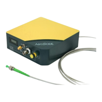
• 1 CCS-I • 1 DC Power Supply (+12V / 4A) • 1 USB-Jack FTDI cable • 1 USB Key with “Aerodiode Control Software Suite” & User manual in pdf • 1 User Manual 4. Product Overview 4.1 Front view of the product 1. -
Page 7: Rear Panel View Of The Device
SMA TTL/LVTTL input voltage connector. The signal must be between 0 and +3.3V on 50 ohms. 4. Power alarm indicator Red LED indicates that the maximal allowed power is reached. If the red light is on, turn down the power with the 6 or 7 control. 5. -
Page 8: Installation
BNC output connector for alarm status (Power or Temperature) monitor. The signal is an inverse TTL, so a +5 V output voltage level corresponds to alarm OFF. 6. Interlock (optional) Input connector for interlock control. It must be shunt in order to have a laser emission. 7. -
Page 9: Software Overview
Click on Connect to start the CCS-I hardware detection. The software will automatically detect any USB-connected CCS-I. A new window will appear for each module. 6. Software overview Page 8/14 – v3.3... - Page 10 CCS-I serial Line number number (address) Control Offset parameter DC parameter Temperature Pulse parameters Interlock status The window is divided in four parts: Triggers in the Control part are used to select the operating mode Numeric boxes in the Pulse Parameters part are used to configure the pulse width, amplitude and repetition rate Page 9/14 –...
-
Page 11: Detailed Controls
The Offset parameter (pulsed mode only) or the DC parameter (CW only) are used to configure the DC current (offset in pulse mode) The Temperature numeric box is used to set the laser diode temperature The Interlock status is ON (green) when the interlock connector is plugged The product serial number is written on the top left of the window. -
Page 12: Trigger And Pulse Width Selection
7.3 Trigger and pulse width selection This three positions switch controls the trigger and the pulse width adjustment. It is only effective in pulsed operation. Internal trigger Internal pulse width adjustment (all software) External trigger (SMA) Internal pulse width adjustment External trigger External pulse width adjustment (all from SMA) -
Page 13: Offset/Dc Current
The values which can be entered in these numerical boxes are limited. The limits mainly depend on various parameters such as the wavelength and the maximum allowed optical power. 7.5 Offset/DC current This item is settable in pulsed and CW operation. It rules the continuous current flowing through the laser diode. -
Page 14: Menu Bar
Config o General config : Restricted access to internal configuration parameters. Please use only this when asked by AERODIODE. o Starting mode : The user can select a starting mode from 4 possible modes which set the product... - Page 15 Info Displays information about the current version and the internal parameters. Help Load this help file Page 14/14 – v3.3...
Need help?
Do you have a question about the Cool & Control Series and is the answer not in the manual?
Questions and answers