Table of Contents
Advertisement
Quick Links
Advertisement
Table of Contents

Related Manuals for Selec GTI Series

Summary of Contents for Selec GTI Series
- Page 1 Creating Best Value SOLAR GRID TIE INVERTER OPERATING INSTRUCTIONS www.selec.com...
- Page 2 INDEX Page No. 1. Manual Overview 1.1 What is inside the manual 1.2 Target group 1.3 Storage of manual 1.4 Additional information 2. Product Overview 2.1 Intended use of inverter 2.2 Inverter overview 2.3 Weight and dimensions 2.4 Type label 2.5 Symbols on the inverter 2.6 Transportation 2.7 Storage...
-
Page 3: Manual Overview
• Before using the inverter, please read all safety and operational instructions and warnings on the unit and in this manual carefully. • Selec Controls Pvt. Ltd. is not liable for any damages caused by failure to observe and follow these instructions in the manual. -
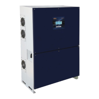
Page 4: Inverter Overview
As shown in Fig 1, the complete system consists of PV array, DC distribution box, GTI-SERIES inverter, AC distribution box and utility grid. 2.2 Inverter Overview 1) Input PV terminals 5) Protective earth terminal 2) DC switch 6) LCD 3) Communication port 7) DB9 RS485 4) AC output 8) Type label 9) DC Fan www.selec.com... -
Page 5: Weight And Dimensions
Made In India Made In India Made In India Made In India Mfg. By: Selec Controls Pvt. Ltd., Mfg. By: Selec Controls Pvt. Ltd., Mfg. By: Selec Controls Pvt. Ltd., Mfg. By: Selec Controls Pvt. Ltd., EL-27/1 EL-27/1 PT, EL-27/2 EL-27/3,... - Page 6 To ensure safe and careful transportation special packaging is used. If any damage is visible, please immediately contact your dealer or Selec Controls Pvt Ltd. Transport of the equipment, especially by road, must be carried out with suitable means for protecting the components, in particular the electronic components from violent shocks, humidity, vibration, etc.
-
Page 7: Safety Instructions
Once you unpack the unit, please ensure that all accessories are present in the box and undamaged. Please contact your dealer if anything is missing or damaged. All the accessories present in the box are listed as follow in Fig 4 & Table 3. MANUAL Fig 4 www.selec.com... - Page 8 AC source or generator. • Make sure DC switch is at OFF position. If it is on ON position switch it to OFF position. www.selec.com...
-
Page 9: Installation Of Inverter
NOTICE • Mount the inverter on rigid, strong surface in such way that it can handle weight of the inverter. • Mount the inverter on such a height that commissioning, decomissioning, turning ON and turning OFF is easily possible. www.selec.com... - Page 10 Install inverter on wall with minimum clearence as shown in fig 7. >300mm >300mm Fig 7 To install more than one inverter in series follow fig 8. for minimum clearance. This clearance should be provided for easy installation, removal & heat dissipation of GTI-SERIES inverter. >300mm >300mm >200mm Fig 8 www.selec.com...
- Page 11 A = 640mm B = 666.5mm Fig 9 Step2 : Mount inverter on anchor bolt with help of at least four people. Tighten the nut and ensure inverter is properly fitted on anchor bolt as per fig 10. Fig 10 www.selec.com...
-
Page 12: Electrical Connections
1) Do not connect PV array positive terminal or negative terminal to the grounding of system. 2) Make sure PV connector's ( Male & female) polarity is proper. 3) Connect PV connectors as shown in fig.13 4) Make sure connectors to Inverter DC terminal are connected properly. www.selec.com... - Page 13 • For the purpose of over current protection use circuit breaker between inverter & utility grid. Use 100A rated AC breaker. • Do not connect any load between inverter & Grid side circuit breaker. • Before starting connection make sure that circuit breaker is OFF. www.selec.com...
- Page 14 Based on local grid standard there are different types of Grid connections available. Compatibility of the inverter for various types of Grid connections is shown in fig 15. GTI Series inverters support 3 phase 4 wire PE (3 -phase, N, PE) & 3 phase 3 wire Ÿ...
-
Page 15: Communication Module
Do not disconnect under load! WIFI / GPRS PV1- PV2- PV3- AC OUTPUT PV1+ PV2+ PV3+ Fig 16 6.3 Communication module The inverter's Communication boards have RS-485, Dry contact & I/O connection (Digital input) terminals as shown in fig 17. www.selec.com... - Page 16 INVERTER GTI -SERIES User Manual FROM LCD RS-485 Termination Switch To Dongle DIGITAL INPUT RS485 CONTACT Power Fig 17 6.3.1 LCD KEY ANNOTATIONS ALARM RED LED GRID GREEN LED ESC KEY ENT KEY DOWN KEY Fig 18 www.selec.com...
- Page 17 1) Error will be visible on screen when they occur. (Refer table no. 7 for Error Definition). 2) When system is on & any self test error occurs screen will jump to self testing page. 3) Use Esc key to go on Home page. www.selec.com...
- Page 18 DATE : 25-01-2021 DOWN KEY TIME : 21 : 46 : 23 TIME : 11 : 46 : 23 ENTER KEY Change Saved NOTE : 1) Press UP key to scroll around digit. 2) Press DOWN key to change digit. www.selec.com...
- Page 19 VOLT LIMIT DOWN PRESS ENT TO LOWER LIMIT 48.0 SET GRID UPPER LIMIT 52.0 FREQ. LIMIT DOWN SET VEN VAL IS 0 SELEC INS VAL 0 DOWN DRY CONTACT TO CHANGE PWD DISABLE PRESS ENT DOWN ENTER PWD RE-ENT PWD...
- Page 20 Connecting single inverter for RS-485 communication : • Connect A+ & A- pin of RS-485 port to the Data +, Data -. Following data format is used for Communication Data Format: Baud rate : 9600 Data bits Stop bit Parity www.selec.com...
- Page 21 INVERTER GTI -SERIES User Manual 6.3.3.2 Monitor inverter status. a) Monitor single inverter's status with RS485 RS485 CONVERTER Fig.19 b) Monitor multiple inverters with RS485 RS485 CONVERTER Fig.20 c) Monitor Inverter with External wireless device Internet Router WIFI Dongle Fig. 21 www.selec.com...
-
Page 22: Troubleshooting
3.Check AC wiring, whether any Line wire is swapped with UV L2 Neutral or ground. L3-Phase Under Voltage UV L3 4.Restart Inverter, if error persists contact Selec Controls Pvt Ltd. OC L1 L1-Phase Over Current 1.Disturbance in AC Voltage. 2.Surge Occurs during operation. - Page 23 2.Check Solar PV enclosure earthing. INS RES Out of Range 3.Check earthing of inverter. 4. Restart Inverter, if error persists contact Selec Controls Pvt Ltd. Inverter Residual Current Restart Inverter, if error persists contact Selec Controls Pvt Ltd. RCMU Out of Range Restart Inverter, if error persists contact Selec Controls Pvt Ltd.
- Page 24 1.Turn OFF DC Switch. 2.Check PV voltage with Multimeter. PV low voltage PV LOW ERR 3.If voltage is more than 250V,"if error persists contact Selec Controls Pvt Ltd." 1.Turn OFF DC Switch. 2.Check AC Voltage on the inverter terminal. GRID Absent/Out of Range 3.Check AC wiring, whether any Line wire is swapped with...
-
Page 25: Commissioning Of Inverter
ADC Sensing Err-PV3 3 Current Sensing Error ADC Sensing Err-L1 Inverter L1-Phase Current Sensing Error 1.Restart Inverter, if error persists contact Selec Controls Pvt Ltd. ADC Sensing Err-L2 Inverter L2-Phase Current Sensing Error ADC Sensing Err-L3 Inverter L3-Phase Current Sensing Error... - Page 26 • Unscrew mounting screws to remove inverter. • Pack inverter in carton which is provided during purchase.If that carton is not available then use equal size carton. • Adopt E-waste Regulation guideline while disposing faulty inverter. Do not dispose inverter with household waste. www.selec.com...
-
Page 27: Technical Specifications
3 phase+N+E Efficiency Max.Efficiency 98.80% 98.80% MPPT Efficiency >99.9% Protection Devices DC reverse polarity protection DC switch Output AC overcurrent protection Output AC overvoltage protection AC/DC Surge Protection Type II / Type II Intergrated all-pole senstive leakage current monitoring unit www.selec.com... - Page 28 Ethernet / Wifi cover screw 0.7 Nm Table 11 10.2 Spare parts and accessories In the following table you will find the optional accessories for your product. If required you can order these from Selec Controls Pvt. Ltd. Description Name Selec Order no. GTI050WLM3PW...
- Page 29 Selec Controls Pvt. Ltd. EL-27-1, Electronic Zone, TTC Industrial Area, MIDC, Mahape, Navi Mumbai 400710, INDIA. Tel.:+91-22-4141 8468 / 452. Fax: +91-22-41418 408. Email: sales@selec.com | www.selec.com Selec USA: www.selec.com/us/en | Selec GmbH: www.selec-europe.com | Selec Australia: www.selec.com/au/en Selec Subsidiaries...
Need help?
Do you have a question about the GTI Series and is the answer not in the manual?
Questions and answers