Table of Contents
Advertisement
Quick Links
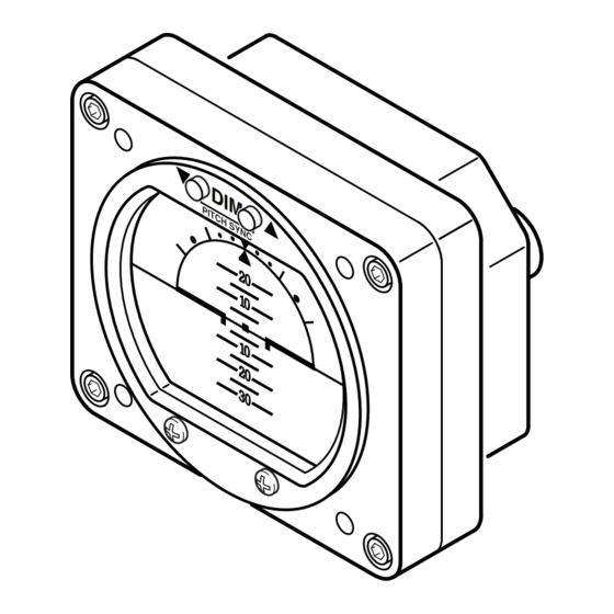
ELECTRIC DIGITAL HORIZON
INSTALLATION/OPERATION GUIDE
KELLY MANUFACTURING COMPANY
555 SOUTH TOPEKA
WICHITA, KS 67202
Rev C December 10, 2018
KMC PUBLICATION NO. 1401-3
RCA2610 SERIES
D I
M
P I T
C H
S Y
N C
2 0
1 0
1 0
2 0
3 0
RCA 2610-3
P/N 102-0403-03-01
P/N 102-0403-05-02
Without Pitch Sync
D I
M
2 0
1 0
1 0
2 0
3 0
RCA 2610-3-G
P/N 102-0403-03-03
P/N 102-0403-05-04
With Pitch Sync
D I M
RCA 2610-2
P/N 102-0403-03-01
P/N 102-0405-05-02
D I M
RCA 2610-2-G
P/N 102-0402-03-03
P/N 102-0402-05-04
KMC
KELLY MANUFACTURING COMPANY
2 0
1 0
1 0
2 0
3 0
2 0
1 0
1 0
2 0
3 0
(316) 265-6868
FAX (316) 265-6687
KELLYMFG.COM
Advertisement
Table of Contents

Related Manuals for Kelly Manufacturing RCA 2610-2 P


Summary of Contents for Kelly Manufacturing RCA 2610-2 P
- Page 1 KMC PUBLICATION NO. 1401-3 KELLY MANUFACTURING COMPANY RCA2610 SERIES ELECTRIC DIGITAL HORIZON INSTALLATION/OPERATION GUIDE With Pitch Sync P I T D I M RCA 2610-3 RCA 2610-2 P/N 102-0403-03-01 P/N 102-0403-03-01 P/N 102-0403-05-02 P/N 102-0405-05-02 Without Pitch Sync D I M...
-
Page 3: Table Of Contents
RCA2610 Series Installation/Operation Guide KELLY MANUFACTURING COMPANY TABLE OF CONTENTS PAGE SECTION 1 INSTRUMENT DESCRIPTION General Description ............2 Physical Description ............2 Display Features ..............5 1.4 Options and Configurations ..........5 SECTION 2 INSTALLATION General Information ............6 Handling ................6 Pre-Installation Inspection .......... -
Page 4: Instrument Description
RCA2610 Series Installation/Operation Guide KELLY MANUFACTURING COMPANY SECTION 1: INSTRUMENT DESCRIPTION 1.1 GENERAL DESCRIPTION An attitude indicator, also known as a gyro horizon or artificial horizon, is an instrument used in an aircraft to inform the pilot of the orientation of the airplane relative to the earth. It indicates pitch (fore and aft tilt) and bank (side to side tilt), and is a primary instru- ment for flight in instrument meteorological conditions. Attitude indicators also have significant applications under visual flight rules. -
Page 5: Figure 1.1, General Dimensions
RCA2610 Series Installation/Operation Guide KELLY MANUFACTURING COMPANY 3.37 0.08 1.22 0.40 PITCH SYNC 3.37 Ø 0.170 THRU (4 PLACES) P I T 1.237 GROUND (TYP) 2.474 9-32 VDC 3.17 (TYP) SPARE SPARE PANEL CUTOUT REAR MOUNTING RCA2610-3 2.75 0.12 1.22 0.40... -
Page 6: Figure 1.2, General Dimensions (-G Models)
RCA2610 Series Installation/Operation Guide KELLY MANUFACTURING COMPANY 3.37 0.08 0.40 1.22 3.37 Ø 0.170 THRU (4 PLACES) 1.237 GROUND (TYP) 9-32 VDC 2.474 3.17 SPARE (TYP) SPARE PANEL CUTOUT REAR MOUNTING RCA2610-3-G 2.75 0.12 1.22 0.40 GROUND 9-32 VDC SPARE SPARE 2.40... -
Page 7: Display Features
RCA2610 Series Installation/Operation Guide KELLY MANUFACTURING COMPANY 1.3 DISPLAY FEATURES See Figure 1.2 below for typical display features. RCA2610-3 shown. 1 ROLL POINTER 2 ROLL DIAL PITCH SYNC PITCH DIAL 3 HORIZON LINE SYMBOLIC AIRPLANE 4 SLIP INDICATOR Figure 1.3, Typical Display Features 1. -
Page 8: Installation
(See Instrument Care on Page 9). 4. To prevent further damage, a malfunctioning instrument should be handled as carefully as a new instrument. Most mal- functioning instruments can be repaired and returned to service. Contact Kelly Manufacturing Company for repair and warranty information. -
Page 9: Operation
RCA2610 Series Installation/Operation Guide KELLY MANUFACTURING COMPANY SECTION 3, OPERATION GUIDE 3.1 PRE-FLIGHT PROCEDURES During pre-flight procedures, the instrument must be provided with adequate electrical power under normal vibration conditions (engine running). A red “X” appears across the screen indicating that the instrument is booting up. When the X disappears, the instrument is ready. The startup process should be completed within three minutes. -
Page 10: In-Flight Procedures - Dimmer
“X” will appear across the screen indicating that the instrument reading is unreliable. It is recommended that you install the Kelly Manufacturing ESP-1 (Emergency Standby Power) backup battery unit. This will ensure that your instrument will have power in the event of Aircraft power failure. Contact your R.C. Allen/Kelly Mfg. distributor for additional information about this product. -
Page 11: General Information
4.1 Flight Testing and Adjustments After flight testing and evaluation, additional calibration my be required depending on the user’s application. Communicate flight test data with Kelly Manufacturing Company to determine appropriate adjustments. 4.2 Instrument Care The most easily damaged part of your instrument is the screen. Special care should be taken when cleaning the screen to prevent scratches and other damage. -
Page 12: Frequently Asked Questions (Faqs)
How do I get my instrument repaired? For any overhaul or repair questions you can contact Kelly Manufacturing Company. Our Service Center can repair or refurbish any R.C. Allen instrument. The only thing really required is information. You can send us your instrument with a letter giving us your name, return shipping address, phone number and a brief description of what is wrong with the instrument or download a form from the Support page on our web site at: kellymfg.com/support.html. -
Page 13: Appendix Ado-160G Environmental Qualification Form
MODEL NUMBER: RCA2610-series TSO NUMBER: C4c & C113a MANUFACTURERS SPECIFICATIONS: STP 1501 Rev. A (12/20/2016) MANUFACTURER: Kelly Manufacturing Company ADDRESS: 555 S. Topeka, Wichita, KS 67202 REVISION & CHANGE NUMBER OF DO-160: Rev. G DATES TESTED: 4/26/16 thru 5/24/16 CONDITIONS...
Need help?
Do you have a question about the RCA 2610-2 P and is the answer not in the manual?
Questions and answers